
Vehicle Standard (Australian Design Rule 113/00 – Acoustic Vehicle Alerting Systems for Quiet Road Transport Vehicles) 2024
I, CAROL BROWN, Assistant Minister for Infrastructure and Transport, determine this national road vehicle standard under section 12 of the Road Vehicle Standards Act 2018.
Dated: 17 January 2024
[SIGNED]
Carol Brown
Assistant Minister for Infrastructure and Transport
CONTENTS
1. legislative provisions
2. FUNCTION
3. APPLICABILITY
4. DEFINITIONS
5. REQUIREMENTS
6. EXEMPTIONS AND ALTERNATIVE PROCEDURES
7. ALTERNATIVE STANDARDS
APPENDIX A
- legislative provisions
- Name of Standard
- This standard is the Vehicle Standard (Australian Design Rule 113/00 – Acoustic Vehicle Alerting Systems for Quiet Road Transport Vehicles) 2024.
- This standard may also be cited as Australian Design Rule 113/00 – Acoustic Vehicle Alerting Systems for Quiet Road Transport Vehicles, the Australian Design Rule 113/00, or ADR 113/00.
- Commencement
- This standard commences on the day after it is registered.
- FUNCTION
- The function of this vehicle standard is to specify minimum sound emission requirements for passenger and goods vehicles that can be propelled for any period of time without an internal combustion engine operating, to aid pedestrians and other vulnerable road users in detecting the presence of those vehicles.
- APPLICABILITY
- This vehicle standard applies to all electrified MA, MB, MC, MD, ME NA, NB and NC category vehicles that can be propelled in at least one forward drive gear or in reverse without an internal combustion engine operating, from the dates set out in clauses 3.1.1 to 3.1.2 and the table under clause 3.3 below.
- 1 November 2025 for all new model vehicles.
- 1 November 2026 for all vehicles.
- For the purposes of clauses 3.1.1 and 3.2.1 above, a “new model” is a vehicle model first produced with a ‘Date of Manufacture’ on or after the date prescribed in each clause.
- Applicability Table
Vehicle Category | ADR Category Code | UN Category Code* | Manufactured on or After** | Acceptable Prior Rules |
Moped 2 wheels | LA | L1 | Not Applicable | |
Moped 3 wheels | LB | L2 | Not Applicable | |
Motor cycle | LC | L3 | Not Applicable | |
Motor cycle and sidecar | LD | L4 | Not Applicable | |
Motor tricycle | LE | L5 | | |
| LEM | | Not Applicable | |
| LEP | | Not Applicable | |
| LEG | | Not Applicable | |
Passenger car | MA | M1 | 1 November 2025 | Nil |
Forward-control passenger vehicle | MB | M1 | 1 November 2025 | Nil |
Off-road passenger vehicle | MC | M1 | 1 November 2025 | Nil |
Light omnibus | MD | M2 | | |
| up to 3.5 tonnes ‘GVM’ and up to 12 seats | MD1 | | 1 November 2025 | Nil |
| up to 3.5 tonnes ‘GVM’ and more than 12 seats | MD2 | | 1 November 2025 | Nil |
| over 3.5 tonnes and up to 4.5 tonnes ‘GVM’ | MD3 | | 1 November 2025 | Nil |
| over 4.5 tonnes and up to 5 tonnes ‘GVM’ | MD4 | | 1 November 2025 | Nil |
Heavy omnibus | ME | M3 | 1 November 2025 | Nil |
Light goods vehicle | NA | N1 | 1 November 2025 | Nil |
Medium goods vehicle | NB | N2 | | |
| over 3.5 tonnes up to 4.5 tonnes ‘GVM’ | NB1 | | 1 November 2025 | Nil |
| over 4.5 tonnes up to 12 tonnes ‘GVM’ | NB2 | | 1 November 2025 | Nil |
Heavy goods vehicle | NC | N3 | 1 November 2025 | Nil |
Very light trailer | TA | O1 | Not Applicable | |
Light trailer | TB | O2 | Not Applicable | |
Medium trailer | TC | O3 | Not Applicable | |
Heavy trailer | TD | O4 | Not Applicable | |
* The category code may also be in the format L1, L2, L3 etc.
** See clauses 3.1 to 3.2
4. DEFINITIONS
4.1. For vehicle categories, definitions and meanings used in this standard, refer to:
4.1.1. Definitions in Appendix A of this standard or an alternative standard at clause 7; and where there is no conflict
4.1.2. Vehicle Standard (Australian Design Rule – Definitions and Vehicle Categories) 2005.
5. REQUIREMENTS
5.1. All electrified vehicles that can be propelled in the normal mode, in reverse or at least one forward drive gear, without an internal combustion engine operating must comply with either:
a) the requirements of Appendix A, as varied by Section 6 – Exemptions and Alternative Procedures; or
b) the technical requirements of the alternative standards set out in Section 7
6. EXEMPTIONS AND ALTERNATIVE PROCEDURES
6.1. Compliance with the following parts, sections and annexes of Appendix A is not required for the purposes of this standard:
Section 3 Application for approval
Section 5 Approval
Section 7 Modifications and extension of the type approval
Section 8 Conformity of production
Section 9 Penalties for non-conformity of production
Section 10 Production definitively discontinued
Section 11 Transitional provisions
Section 12 Names and addresses of Technical Services responsible for conducting approval tests and of Type Approval Authorities
6.2. In paragraph 3.2.1 of Annex 3 to Appendix A omit “in agreement with the Technical Service”.
6.3. In paragraph 4.2 of Annex 3 to Appendix A omit “Technical Service” , substitute “Approved Testing Facility”.
6.4. Completed NB, NC and ME category vehicles fitted with an Acoustic Vehicle Alerting System (AVAS) need not be tested in accordance with the following parts of Appendix A to demonstrate compliance to this vehicle standard:
- Sections 6.2.1.2 (b) and (c);
- Section 6.2.3, including sub sections 6.2.3.1 and 6.2.3.2; and
- Annex 3, Section 2.3
if:
(a) the AVAS is identical in specification to an AVAS that is fitted to another vehicle of the same category that has been entered on the Register of Approved Vehicles; and
(b) the completed vehicle does not differ essentially from that vehicle with respect to:
- the shape and the materials of the bodywork of the vehicle which affect the sound emitted;
- the drivetrain including the source of propulsion;
- the number of axles;
- if applicable, the number and type(s) of sound emitting devices (hardware) of AVAS fitted on the vehicle; and
- if applicable, the position of the AVAS on the vehicle.
6.5. A vehicle need not be fitted with an AVAS system that operates when the vehicle is propelled in reverse if a Reversing Alarm is fitted that operates over the full speed range required in paragraph 6.2 to Appendix A of this standard and:
6.5.1. meets the requirements of clause 23.2 of Vehicle Standard (Australian Design Rule 42/05 – General Safety Requirements) 2018 and meets the overall minimum sound limit levels as per paragraph 6.2. of Appendix A to this standard; or
6.5.2. for applicable vehicle categories, meets the technical requirements United Nations Regulation No. 165 UNIFORM PROVISIONS CONCERNING THE APPROVAL OF AUDIBLE REVERSE WARNING DEVICES AND OF MOTOR VEHICLES WITH REGARD TO THEIR AUDIBLE REVERSE WARNING SIGNALS.
7. ALTERNATIVE STANDARDS
7.1. The technical requirements of United Nations Regulation No. 138 – UNIFORM PROVISIONS CONCERNING THE APPROVAL OF QUIET ROAD TRANSPORT VEHICLES WITH REGARD TO THEIR REDUCED AUDIBILITY, incorporating all amendments up to and including the 01 series of amendments.
7.2. The technical requirements of the United States Code of Federal Regulations (CFR), Part 571 – Federal Motor Vehicle Safety Standards - Subpart B 49 CFR 571.141 Standard No. 141 – MINIMUM SOUND REQUIREMENTS FOR HYBRID AND ELECTRIC VEHICLES.
Regulation No. 138
Uniform provisions concerning the approval of quiet road transport vehicles with regard to their reduced audibility
Contents
Page
Regulation
1. Scope................................................................... 4
2. Definitions ........................................................ 4
3. Application for approval ............................................... 7
4. Markings ......................................................... 7
5. Approval ......................................................... 7
6. Specifications....................................................... 8
7. Modification and extension of approval of a vehicle type.......................... 10
8. Conformity of production............................................... 11
9. Penalties for non-conformity of production.................................... 11
10. Production definitively discontinued........................................ 11
11. Transitional provisions................................................. 11
12. Names and addresses of Technical Services responsible for conducting approval tests
and of Type Approval Authorities.......................................... 12
Annexes
1 Communication..................................................... 13
Addendum to the Communication Form (Technical Information document) .............. 15
2 Arrangements of the approval mark........................................ 19
3 Methods and instruments for measuring the sound made by motor vehicles............... 20
Appendix: Figures and Flowcharts......................................... 33
1. Scope
This Regulation applies to electrified vehicles of categories M and N which can be propelled in the normal mode, in reverse or at least one forward drive gear, without an internal combustion engine operating in respect to their audibility.
2. Definitions
For the purpose of this Regulation,
2.1. "Approval of a vehicle" means the approval of a vehicle type with regard to sound.
2.2. "Acoustic Vehicle Alerting System" (AVAS) means a component or set of components installed in vehicles with the primary purpose to fulfil the requirements of this Regulation.
2.3. "Vehicle type" means a category of motor vehicles which does not differ essentially in such respects as:
2.3.1. The shape and the materials of the bodywork of the vehicle which affect the sound level emitted;
2.3.2. The principle of the drivetrain (from the batteries to the wheels).
Notwithstanding the provisions of paragraph 2.3.2. vehicles which differ with respect to overall gear ratios, battery type or the fitment of a range extender may be considered vehicles of the same type;
2.3.3. If applicable, the number and type(s) of sound emitting devices (hardware) of AVAS fitted on the vehicle.
2.3.4. If applicable, the position of the AVAS on the vehicle.
2.4. "Frequency Shift" means the variation of the frequency content of the AVAS sound as a function of the vehicle speed.
2.5. "Electrified vehicle" means a vehicle with a powertrain containing at least one electric motor or electric motor-generator.
2.5.1. "Pure Electric Vehicle" (PEV) means a motor vehicle with an electric motor as its sole mean of propulsion.
2.5.2. "Hybrid Electric Vehicle" (HEV) means a vehicle with a powertrain containing at least one electric motor or electric motor generator and at least one internal combustion engine as propulsion energy converters.
2.5.3. "Fuel Cell Vehicle"” (FCV) means a vehicle with a fuel cell and an electric machine as propulsion energy converters.
2.5.4. "Fuel Cell Hybrid Vehicle" (FCHV) means a vehicle with at least one fuel storage system and at least one Rechargeable Electric Energy Storage System (REESS) as propulsion energy storage system.
2.6. "Mass in running order" means the mass of the vehicle, with its fuel tank(s) filled to at least 90 per cent of its or their capacity/ies, including the mass of the driver (75 kg), of the fuel and liquids, fitted with the standard equipment in accordance with the manufacturer's specifications and, when they are fitted, the mass of the bodywork, the cabin, the coupling and the spare wheel(s) as well as the tools.
2.7. "Pause function" means a mechanism to enable the driver to halt the operation of an AVAS.
2.8. "Front plane of the vehicle" means a vertical plane tangent to the leading edge of the vehicle.
2.9. "Rear plane of the vehicle" means a vertical plane tangent to the trailing edge of the vehicle.
2.10. Symbols and abbreviated terms and the paragraph in which they are first used.
Table 1
Symbols and Abbreviations
Symbol | Unit | Paragraph | Explanation |
ICE | - | 6.2. | Internal Combustion Engine |
AA' | - | Annex 3 para.3. | Line perpendicular to vehicle travel which indicates the beginning of the zone to record sound pressure level during test |
BB' | - | Annex 3 para.3. | Line perpendicular to vehicle travel which indicates end of the zone to record sound pressure level during test |
PP' | - | Annex 3 para 3. | Line perpendicular to vehicle travel which indicates location of microphones |
CC' | - | Annex 3 para.3. | Centreline of vehicle travel |
vtest | km/h | Annex 3 para.3. | Target vehicle test velocity |
j | - | Annex 3 para.3. | Index for single test run within standstill or constant speed test conditions |
Lreverse | dB(A) | Annex 3 para.3. | Vehicle A-weighted sound pressure level for reversing test |
Lcrs,10 | dB(A) | Annex 3 para.3. | Vehicle A-weighted sound pressure level for constant speed test at 10 km/h. |
Lcrs,20 | dB(A) | Annex 3 para.3. | Vehicle A-weighted sound pressure level for constant speed test at 20 km/h. |
Lcorr | dB(A) | Annex 3 para.2.3.2. | Background noise correction |
Ltest,j | dB(A) | Annex 3 para.2.3.2. | A-weighted sound pressure level result of jth test run |
Ltestcorr,j | dB(A) | Annex 3 para.2.3.2. | A-weighted sound pressure level result of jth test run corrected for background noise |
Lbgn | dB(A) | Annex 3 para.2.3.1. | Background A-weighted sound pressure level. |
∆Lbgn, p-p | dB(A) | Annex 3 para.2.3.2. | Range of maximum to minimum value of the representative background noise A-weighted sound pressure level over a defined time period. |
∆L | dB(A) | Annex 3 para.2.3.2. | A-weighted sound pressure level of jth test result minus the A-weighted background noise level (∆L = Ltest,j - Lbgn) |
vref | km/h | Annex 3 para.4. | Reference vehicle velocity used for calculating frequency shift percentage. |
fj, speed | Hz | Annex 3 para.4. | Single frequency component at a given vehicle speed per sample segment, e.g. f1, 5 |
fref | Hz | Annex 3 para.4. | Single frequency component at reference vehicle speed |
fspeed | Hz | Annex 3 para.4. | Single frequency component at a given vehicle speed, e.g. f5 |
lveh | m | Annex 3, Appendix | Length of vehicle |
3. Application for approval
3.1. The application for approval of a vehicle type with regard to reduced audibility shall be submitted by its manufacturer or by a duly accredited representative.
3.2. It shall be accompanied by the undermentioned documents and the following particulars:
3.2.1. A description of the vehicle type with regard to the items mentioned in paragraph 2.3. above;
3.2.2. A description of the engine(s) as mentioned in Annex 1, Addendum;
3.2.3. If applicable, a list of the components constituting the AVAS;
3.2.4. If applicable, a drawing of the assembled AVAS and an indication of its position on the vehicle.
3.3. In the case of paragraph 2.3., the single vehicle, representative of the type in question, will be selected by the Technical Service conducting approval tests, in accordance with the vehicle manufacturer.
3.4. The Type Approval Authority shall verify the existence of satisfactory arrangements for ensuring effective control of the conformity of production before type approval is granted.
4. Markings
4.1. The components of the AVAS (if applicable) shall bear:
4.1.1. The trade name or mark of the manufacturer(s) of the AVAS components;
4.1.2. A designated identification number(s).
4.2. These markings shall be clearly legible and be indelible.
5. Approval
5.1. Type approval shall only be granted if the vehicle type meets the requirements of paragraphs 6. and 7. below.
5.1.1 In case of hybrid vehicles, equipped with an internal combustion engine: if the manufacturer can demonstrate to the Type Approval Authority that the vehicle cannot be assessed according to the provisions of the Regulation because the internal combustion engine used for direct propulsion will be operational during the specified tests within this regulation, this Regulation shall be deemed not applicable to this vehicle.
5.2. An approval number shall be assigned to each type approved. Its first two digits (at present 01 corresponding to the 01 series of amendments) shall indicate the series of amendments incorporating the most recent major technical amendments made to this Regulation at the time of issue of the approval. The same Contracting Party shall not assign the same number to another vehicle type.
5.3. Notice of approval or of extension or of refusal or withdrawal of approval or of production definitively discontinued of a vehicle type pursuant to this Regulation shall be communicated to the Parties to the Agreement applying this Regulation by means of a form conforming to the model in Annex 1 to this Regulation.
5.4. There shall be affixed to every vehicle conforming to a vehicle type approved under this Regulation, conspicuously and in a readily accessible place specified on the approval form, an international approval mark consisting of:
5.4.1. A circle surrounding the letter "E" followed by the distinguishing number of the country which has granted approval;
5.4.2. The number of this Regulation, followed by the letter "R", a dash and the approval number to the right of the circle prescribed in paragraph 5.4.1.
5.5. If the vehicle conforms to a vehicle type approved, under one or more other Regulations annexed to the Agreement, in the country which has granted approval under this Regulation, the symbol prescribed in paragraph 5.4.1. need not be repeated. In such a case the regulation and approval numbers and the additional symbols of all the Regulations under which approval has been granted in the country which has granted approval under this Regulation shall be placed in vertical columns to the right of the symbol prescribed in paragraph 5.4.1.
5.6. The approval mark shall be clearly legible and indelible.
5.7. The approval mark shall be placed close to or on the vehicle data plate affixed by the manufacturer.
5.8. Annex 2 to this Regulation gives examples of arrangements of the approval mark.
6. Specifications
6.1. General specifications
For the purpose of this Regulation, the vehicle shall fulfil the following requirements:
6.2. Acoustics characteristics
The sound emitted by the vehicle type submitted for approval shall be measured by the methods described in Annex 3 to this Regulation.
The specifications of this Regulation are applicable for the speed range of greater than 0 km/h up to and inclusive 20 km/h. Operation of an AVAS is permitted at vehicle speeds outside the specification range. AVAS may be operational independent of the operation of an internal combustion engine inside or outside of the specified operation range.
If the vehicle that is not equipped with an AVAS fulfils the overall levels as specified in Table 2 below with a margin of +3 dB(A), the specification for one-third octave bands and the frequency shift do not apply.
6.2.1. Constant speed tests
6.2.1.1. The test speeds for approval are 10 km/h and 20 km/h.
6.2.1.2. When tested under the conditions of Annex 3 paragraph 3.3.2., the vehicle shall emit a sound:
(a) That has a minimum overall sound pressure level for the applicable test speed according to Table 2 of paragraph 6.2.8.;
(b) That has at least two of the one-third octave bands according to Table 2 of paragraph 6.2.8. At least one of these bands shall be below or within the 1,600 Hz one-third octave band;
(c) With minimum sound pressure levels in the chosen bands for the applicable test speed according to Table 2 of paragraph 6.2.8., column 3 or column 4.
6.2.1.3. If after a vehicle is tested in accordance with Annex 3 paragraph 3.3.2., for ten consecutive times within a series of measurements without recording a valid measurement because the vehicle's internal combustion engine (ICE) remains active or restarts and interferes with the measurements, the vehicle is exempted from this particular test.
6.2.2. Reversing test
6.2.2.1. When tested under the conditions of Annex 3 paragraph 3.3.3. the vehicle shall emit a sound that has a minimum overall sound pressure level according to Table 2 of paragraph 6.2.8., column 5.
6.2.2.2. If after a vehicle is tested in accordance with Annex 3, paragraph 3.3.3., for ten consecutive times within a series of measurements without recording a valid measurement because the vehicle's ICE remains active or restarts and interferes with the measurements, the vehicle is exempted from this particular test.
6.2.3. Frequency shift to signify acceleration and deceleration
6.2.3.1. The intention of frequency shift is to acoustically inform road users about the change in vehicle speed.
6.2.3.2. When tested under the conditions of Annex 3 paragraph 4, at least one tone within the frequency range as specified in paragraph 6.2.8. emitted by the vehicle shall vary proportionally with speed within each individual gear ratio by an average of at least 0.8 % per 1 km/h in the speed range from 5 km/h to 20 km/h inclusive when driving in forward direction. In case more than one frequency is shifted, only one frequency shift needs to fulfil the requirements.
6.2.4. Stationary sound
The vehicle may emit a sound when stationary.
6.2.5. Driver selectable sounds
The vehicle manufacturer may define alternative sounds which can be selected by the driver; each of these sounds shall be in compliance and approved with the provisions in paragraphs 6.2.1. to 6.2.3.
6.2.6 AVAS Sound Level Variation
If fitted, an AVAS may operate at different sound levels either automatically managed by the control unit or manually selected by the driver, each selected sound level shall be in compliance with the specifications outlined in paragraphs 6.2.1. to 6.2.3. and paragraphs 6.2.8. and 6.2.9.
6.2.7. Pause function
Any pause function as defined in paragraph 2.7. shall be prohibited.
6.2.8. Specifications on maximum sound level for AVAS
When tested under the conditions of Annex 3 paragraph 3.3.2., a vehicle which is equipped with an AVAS, shall not emit an overall sound level of more than 75 dB(A), if driving in forward direction.[4]
6.2.9. Minimum sound levels
The sound level measured in accordance with the provisions of Annex 3 to this Regulation, mathematically rounded to the nearest integer value, shall have at least the followings values:
Table 2
Minimum Sound Level Requirements in dB(A)
Frequency
in Hz | Constant Speed Test paragraph 3.3.2.
(10 km/h) | Constant Speed Test
paragraph 3.3.2.
(20 km/h) | Reversing Test paragraph 3.3.3. |
Column 1 | Column 2 | Column 3 | Column 4 | Column 5 |
Overall | 50 | 56 | 47 |
| 160 | 45 | 50 | |
200 | 44 | 49 |
250 | 43 | 48 |
315 | 44 | 49 |
400 | 45 | 50 |
500 | 45 | 50 |
630 | 46 | 51 |
800 | 46 | 51 |
1,000 | 46 | 51 |
1,250 | 46 | 51 |
1,600 | 44 | 49 |
2,000 | 42 | 47 |
2,500 | 39 | 44 |
3,150 | 36 | 41 |
4,000 | 34 | 39 |
5,000 | 31 | 36 |
7. Modification and extension of approval of a vehicle type
7.1. Every modification of the vehicle type shall be notified to the Type Approval Authority which approved the vehicle type. The Type Approval Authority may then either:
7.1.1. consider that the modifications made are unlikely to have an appreciable adverse effect and that in any case the vehicle still complies with the requirements, or
7.1.2. require a further test report from the Technical Service responsible for conducting the tests.
7.2. Confirmation or refusal of approval, specifying the alterations shall be communicated by the procedure specified in paragraph 5.3. above to the Parties to the Agreement applying this Regulation.
7.3. The Type Approval Authority issuing the extension of approval shall assign a series number for such an extension and inform thereof the other Parties to the 1958 Agreement applying this Regulation by means of a communication form conforming to the model in Annex 1 to this Regulation.
8. Conformity of production
The conformity of production procedures shall comply with those set out in the Agreement, Schedule 1 (E/ECE/TRANS/505/Rev.3) with the following requirements:
8.1. Vehicles approved according to this Regulation shall be manufactured so as to conform to the type approved and satisfy the requirements set forth in paragraph 6.2. above;
8.2. The Type Approval Authority which has granted type approval may at any time verify the conformity control methods applied in each production facility. The normal frequency of these verifications shall be one every two years.
9. Penalties for non-conformity of production
9.1. The approval granted in respect of a vehicle type pursuant to this Regulation may be withdrawn if the requirements set forth above are not met.
9.2. If a Contracting Party to the Agreement applying this Regulation withdraws an approval it has previously granted, it shall forthwith so notify the other Contracting Parties applying this Regulation, by means of a communication form conforming to the model in Annex 1 to this Regulation.
10. Production definitively discontinued
If the holder of the approval completely ceases to manufacture a vehicle type approved in accordance with this Regulation, he shall so inform the Type Approval Authority which granted the approval. Upon receiving the relevant communication that Type Approval Authority shall inform thereof the other Parties to the 1958 Agreement applying this Regulation by means of a communication form conforming to the model in Annex 1 to this Regulation.
11. Transitional provisions
11.1. Until 30 June 2019 ISO 10844:1994 may be applied as an alternative to ISO 10844:2014 to check compliance of the test track as described in Annex 3, paragraph 2.1.2. of this Regulation.
11.2. As from the official date of entry into force of the 01 series of amendments, no Contracting Party applying this Regulation shall refuse to grant or refuse to accept type approvals under this Regulation as amended by the 01 series of amendments.
11.3. As from 1 September 2019, Contracting Parties applying this Regulation shall not be obliged to accept type approvals to this Regulation in its original version, first issued after 1 September 2019.
11.4. Until 1 September 2021, Contracting Parties applying this Regulation shall accept type approvals to this Regulation in its original version, first issued before 1 September 2019.
11.5. As from 1 September 2021, Contracting Parties applying this Regulation shall not be obliged to accept type approvals to this Regulation in its original version.
11.6. Notwithstanding paragraphs 11.3. to 11.5. above, type approvals granted to this Regulation in its original version, which are not affected by the 01 series of amendments, shall remain valid and Contracting Parties applying this Regulation shall accept them.
11.7. Notwithstanding the transitional provisions above, Contracting Parties whose application of this Regulation comes into force after the date of entry into force of the 01 series of amendments are not obliged to accept type approvals which were granted in accordance with this Regulation in its original version and are only obliged to accept type approval granted in accordance with the 01 series of amendments.
11.8. Contracting Parties applying this Regulation shall not refuse to grant type approvals, or extensions thereof, under this Regulation in its original version.
12. Names and addresses of Technical Services responsible for conducting approval tests and of Type Approval Authorities
The Contracting Parties to the 1958 Agreement applying this Regulation shall communicate to the United Nations Secretariat the names and addresses of the Technical Services responsible for conducting approval tests and of the Type Approval Authorities which grant approval and to which forms certifying approval or extension or refusal or withdrawal of approval, issued in other countries, are to be sent.
Annex 1
Communication
(maximum format: A4 (210 x 297 mm))

[5]
Concerning:[6] Approval granted
Approval extended
Approval refused
Approval withdrawn
Production definitively discontinued
of a vehicle type with regard to its sound emission pursuant to UN Regulation No. 138
Approval No. …………………….. Extension No. ……………………………
Section I
0.1. Make (trade name of manufacturer): ..........................
0.2. Vehicle Type:..........................................
0.3. Means of identification of type if marked on the vehicle:[7]............
0.3.1. Location of that marking:..................................
0.4. Category of vehicle:[8]....................................
0.5. Propulsion principle (PEV/HEV/FCV/FCHV):....................
0.6. Company name and address of manufacturer:.....................
0.7. Names and Address(es) of assembly plant(s): .....................
0.8. Name and address of the manufacturer's representative (if any):.........
Section II
1. Additional information (where applicable): See Addendum
2. Technical Service responsible for carrying out the tests: ..............
3. Date of test report: ......................................
4. Number of test report: ....................................
5. Remarks (if any): See Addendum
6. Place: ...............................................
7. Date: ...............................................
8. Signature: ............................................
9. Reasons for Extensions
Attachments:
Information package
Test report(s)
Addendum to the communication form No …
Technical Information
0. General
0.1. Make (trade name of manufacturer):
0.2. Means of identification of type, if marked on the vehicle:[9]
0.2.1. Location of that marking:
0.3 Category of vehicle:[10]
0.4. Company name and address of manufacturer:
0.5. Name and address of the manufacturer's representative (if any):
0.6. Name(s) and Address(es) of assembly plant(s):
1. Additional information
1.1. Power plant
1.1.1. Propulsion principle (PEV/HEV/FCV/FCHV) :
1.1.2. Manufacturer of the engine(s):
1.1.3. Manufacturer's engine code(s):
1.2. Description of AVAS (if applicable): ..........
1.2.1. Sound at Stationary (yes/no)
1.2.2. No. of driver selectable sounds (1/2/3/…)
2. Test results
2.1. Sound level of moving vehicle: .......... dB(A) at 10 km/h
2.2. Sound level of moving vehicle: .......... dB(A) at 20 km/h
2.3. Sound level of moving vehicle: …...... dB(A) in reversing
2.4. Frequency shift: .......... % /km/h
3. Remarks
Technical Information Document[11]
0. General
0.1. Make (trade name of manufacturer):...........................
0.2. Type
0.3. Means of identification of type, if marked on the vehicle:[12]
0.3.1. Location of that marking:..................................
0.4. Category of vehicle:[13]...................................
0.5. Company name and address of manufacturer:.....................
0.6. Name and address of the manufacturer's representative (if any):.........
0.8. Name(s) and Address(es) of assembly plant(s):....................
1. General construction characteristics of the vehicle
1.1. Photographs and/or drawings of a representative vehicle:.............
1.3. Number of axles and wheels:[14].............................
1.3.3. Powered axles (number, position, interconnection):.................
1.6. Position and arrangement of the engine(s):.......................
2. Masses and dimensions[15] (in kg and mm) (Refer to drawing where applicable):
2.4. Range of vehicle dimensions (overall):.........................
2.4.1 For chassis without bodywork:...............................
2.4.1.1. Length:..............................................
2.4.1.2. Width:...............................................
2.4.2. For chassis with bodywork
2.4.2.1. Length:..............................................
2.4.2.2. Width:...............................................
2.6. Mass in running order
minimum and maximum:..................................
3. Power plant[16]
3.1. Manufacturer of the engine(s):
3.1.1. Manufacturer's engine code(s) (as marked on the engine(s), or other means of identification):
3.3. Electric motor
3.3.1. Type of the electric motor (winding, excitation):
3.4. Engine or motor combination:
3.4.4. Electric motor (describe each type of electric motor separately)
3.4.4.1. Make:...............................................
3.4.4.2. Type:...............................................
3.4.4.3. Maximum power: …..kW
6. Suspension
6.6. Tyre size
6.6.2. Upper and lower limits of rolling radii
6.6.2.1. Axle 1:..............................................
6.6.2.2. Axle 2:..............................................
6.6.2.3. Axle 3:..............................................
6.6.2.4. Axle 4:..............................................
etc.
9. Bodywork
9.1. Type of bodywork:
9.2. Materials used and methods of construction:
12. Miscellaneous
12.5. Details of materials and components influencing the sound emission of the vehicle (if not covered by other items):
17. AVAS (if applicable)
17.1. Type of the AVAS (loudspeaker …):...........................
17.1.1. Make:...............................................
17.1.2. Type:...............................................
17.1.3. Geometrical characteristics (internal length and diameter)
17.2. The following documents are annexed to this communication:
17.2.1. ... drawings of the mountings of the sound emitting device(s),
17.2.2. ... drawings and diagrams giving the mounting positions and characteristics of the parts of the structure on which the devices are fitted.
17.2.3. ... over-all views of the front of the vehicle and of the compartment in which the device is situated and description of the component materials.
Signed: ...................................................
Position in company:...............................................
Date: ...................................................
Annex 2
Arrangements of the approval mark
Model A
(See paragraph 5.4. of this Regulation)

a = 8 mm min.
The above approval mark affixed to a vehicle shows that the vehicle type concerned has, with regard to its audibility, been approved in the Netherlands (E 4) pursuant to UN Regulation No. 138 under approval No. 012439.
The first two digits of the approval number indicate that UN Regulation No. 138 already included the 01 series of amendments when the approval was granted.
Model B
(See paragraph 5.5. of this Regulation)

a = 8 mm min.
The above approval mark affixed to a vehicle shows that the vehicle type concerned has been approved in the Netherlands (E 4) pursuant to UN Regulations Nos. 138 and 33.[17] The approval numbers indicate that, at the dates when the respective approvals were granted, UN Regulation No. 138 included the 01 series of amendments while UN Regulation No. 33 included the 01 series of amendments.
Annex 3
Methods and instruments for measuring the sound made by motor vehicles
1. Instrumentation
1.1. Instruments for acoustic measurement
1.1.1. General
The apparatus used for measuring the sound pressure level shall be a sound level meter or equivalent measurement system meeting the requirements of Class 1 instruments (inclusive of the recommended windscreen, if used). These requirements are described in IEC 61672-1-2013.
The entire measurement system shall be checked by means of a sound calibrator that fulfils the requirements of Class 1 sound calibrators in accordance with IEC 60942-2003.
Measurements shall be carried out using the time weighting "F" of the acoustic measurement instrument and the "A" frequency weighting also described in IEC 61672-1-2013. When using a system that includes a periodic monitoring of the A-weighted sound pressure level, a reading should be made at a time interval not greater than 30 ms.
When measurements are carried out for one-third octaves, the instrumentation shall meet all requirements of IEC 61260-1-2014, class 1.
When measurements are carried out for frequency shift, the digital sound recording system shall have at least a 16 bit quantization. The sampling rate and the dynamic range shall be appropriate to the signal of interest.
The instruments shall be maintained and calibrated in accordance with the instructions of the instrument manufacturer.
1.1.2. Calibration
At the beginning and at the end of every measurement session, the entire acoustic measurement system shall be checked by means of a sound calibrator as described in paragraph 1.1.1.. Without any further adjustment, the difference between the readings shall be less than or equal to 0,5 dB(A). If this value is exceeded, the results of the measurements obtained after the previous satisfactory check shall be discarded.
1.1.3. Compliance with requirements
Compliance of the sound calibrator with the requirements of IEC 60942-2003 shall be verified once a year. Compliance of the instrumentation system with the requirements of IEC 61672-3-2013 shall be verified at least every 2 years. All compliance testing shall be conducted by a laboratory which is authorized to perform calibrations traceable to the appropriate standards.
1.2. Instrumentation for speed measurements
The road speed of the vehicle shall be measured with instruments meeting specification limits of at least ±0,5 km/h when using continuous measuring devices.
If testing uses independent measurements of speed, this instrumentation shall meet specification limits of at least ±0,2 km/h.
1.3. Meteorological instrumentation
The meteorological instrumentation used to monitor the environmental conditions during the test shall meet the specifications of:
(a) ±1 °C or less for a temperature measuring device;
(b) ±1,0 m/s for a wind speed-measuring device;
(c) ±5 hPa for a barometric pressure measuring device;
(d) ±5 % for a relative humidity measuring device.
2. Acoustic environment, meteorological conditions, and background noise
2.1. Test site
2.1.1. General
The specifications for the test site provide the necessary acoustic environment to carry out the vehicle tests documented in this Regulation. Outdoor and indoor test environments that meet the specifications of this Regulation provide equivalent acoustic environments and produce results that are equally valid.
2.1.2. Outdoor testing
The test site shall be substantially level. For the measurement of vehicles in motion, the test track construction and surface shall meet the requirements of ISO 10844:2014. For the measurement of vehicles at a standstill, the test area shall be either:
(a) ISO 10844:2014; or
(b) Other dense asphalt; or
(c) Dense concrete.
Within a radius of 50 m around the centre of the track, the space shall be free of large reflecting objects such as fences, rocks, bridges or buildings. The test track and the surface of the site shall be dry and free from absorbing materials such as powdery snow, or loose debris.
In the vicinity of the microphones, there shall be no obstacle that could influence the acoustic field and no person shall remain between the microphone and the noise source. The meter observer shall be positioned so as not to influence the meter reading. Microphones shall be located as specified in Figures 1 of the Appendix to this annex.
2.1.3. Indoor hemi anechoic or anechoic testing
This paragraph specifies conditions applicable when testing a vehicle, either operating as it would on the road with all systems operational, or operating in a mode where only the AVAS is operational.
The test facility shall meet requirements of ISO 26101:2012 with the following qualification criteria and measurement requirements appropriate to this test method.
Space to be deemed hemi-anechoic shall be defined as shown in Figure 3 of the Appendix to this annex.
For qualifying the hemi acoustic space, the following evaluation shall be conducted:
(a) Sound source location shall be place on the floor in middle of the space deemed to be anechoic;
(b) Sound source shall provide a broadband input for measurement;
(c) Evaluation shall be conducted in one-third-octave bands;
(d) Microphone locations for evaluation shall be on a line from the source location to each position of microphones used for measurement in this Regulation as shown in Figure 3 of the Appendix to this annex. This is commonly referred to as the microphone transverse;
(e) A minimum of 10 points shall be used for evaluation on the microphone transverse line;
(f) The one third octave bands used to establish hemi-anechoic qualification shall be defined to cover the spectral range of interest.
The test facility shall have a cut-off frequency, as defined in ISO 26101:2012, lower than the lowest frequency of interest. The lowest frequency of interest is the frequency below which there is no signal content relevant to the measurement of sound emission for the vehicle under test.
In the vicinity of the microphones, there shall be no obstacle that could influence the acoustic field and no person shall remain between the microphone and the noise source. The meter observer shall be positioned so as not to influence the meter reading. Microphones shall be located as specified in Figures 2 of the Appendix to this annex.
2.2. Meteorological conditions
2.2.1. For outdoor facilities
Meteorological conditions are specified to provide a range of normal operating temperatures and to prevent abnormal readings due to extreme environmental conditions.
The meteorological instrumentation shall deliver data representative for the test site and shall be positioned adjacent to the test area at a height representative of the height of the measuring microphone.
A value representative of temperature, wind speed, relative humidity, and barometric pressure shall be recorded during the measurement interval.
The measurements shall be made when the ambient air temperature is within the range from 5 °C to 40 °C.
The ambient temperature may of necessity be restricted to a narrower temperature range such that all key vehicle functionalities that can reduce vehicle noise emissions (e.g. start/stop, hybrid propulsion, battery propulsion, fuel-cell stack operation) are enabled according to manufacturer's specifications.
The tests shall not be carried out if the wind speed, including gusts, at microphone height exceeds 5 m/s, during the measurement interval.
2.2.2. For indoor facilities
Meteorological conditions are specified to provide a range of normal operating temperatures and to prevent abnormal readings due to extreme environmental conditions.
The meteorological instrumentation shall deliver data representative for the test site and values of temperature, relative humidity, and barometric pressure shall be recorded during the measurement interval.
The measurements shall be made when the ambient air temperature is within the range from 5 °C to 40 °C.
The ambient temperature may of necessity be restricted to a narrower temperature range such that all key vehicle functionalities that can reduce vehicle noise emissions (e.g. start/stop, hybrid propulsion, battery propulsion, fuel-cell stack operation) are enabled according to manufacturer's specifications.
2.3. Background noise
2.3.1. Measurement criteria for A-weighted sound pressure level
The background, or ambient noise, shall be measured for a duration of at least 10 seconds. A 10 second sample taken from these measurements shall be used to calculate the reported background noise, ensuring the 10 seconds sample selected is representative of the background noise in absence of any transient disturbance. The measurements shall be made with the same microphones and microphone locations used during the test.
When testing in an indoor facility, the noise emitted by the roller-bench, chassis dynamometer or other test facility equipment, without the vehicle installed or present, inclusive of the noise caused by air handling of the facility and vehicle cooling, shall be reported as the background noise.
The recorded maximum A-weighted sound pressure level from both microphones during the 10 second sample shall be reported as the background noise, Lbgn, for both left and right microphones.
For each 10 second sample at each microphone, the maximum to minimum range of the background noise, ∆Lbgn, p-p, shall be reported.
The one-third-octave frequency spectrum, corresponding to the reported maximum level of background noise in the microphone with the highest background level, shall be reported.
As an aid for measurement and reporting of background noises see flowchart in Figure 4 of the Appendix to this annex.
2.3.2. Vehicle A-weighted sound pressure level measurement correction criteria
Depending on the level and the range of maximum to minimum value of the representative background noise A-weighted sound pressure level over a defined time period, the measured jth test result within a test condition, Ltest,j, shall be corrected according to the table below to obtain the background noise corrected level Ltestcorr,j. Except where noted, Ltestcorr,j = Ltest,j - Lcorr.
Background noise corrections to measurements are only valid when the range of the maximum to minimum background noise A-weighted sound pressure levels are 2 dB(A) or less.
In all cases where the range of the maximum to minimum background noise is greater than 2 dB(A), the maximum level of the background noise shall be 10 dB(A) or greater below the level of the measurement. When the maximum to minimum range of background noise is greater than 2 dB(A) and the level of the background noise is less than 10 dB(A) below the measurement, no valid measurement is possible.
Table 3
Correction for level of background noise when measuring vehicle A-weighted sound pressure level
Correction for background noise |
Range of maximum to minimum value of the representative background noise A-weighted sound pressure level over a defined time period
∆Lbgn, p-p in dB(A) | Sound pressure level of j-th test result minus background noise level ∆L = Ltest,j - Lbgn in dB(A) | Correction in dB(A) Lcorr |
- | ∆L > 10 | no correction needed |
< 2 | 8 ≤ ∆L <10 | 0,5 |
6 ≤ ∆L <8 | 1,0 |
4.5 ≤ ∆L <6 | 1,5 |
3 ≤ ∆L <4.5 | 2,5 |
∆L < 3 | no valid measurement
can be reported |
If a sound peak obviously out of character with the general sound pressure level is observed, that measurement shall be discarded.
As an aid for measurement correction criteria see flowchart in Figure 5 of the appendix to this annex.
2.3.3. Background noise requirements when analysing in one-third-octave bands
When analysing one-third octaves according to this Regulation, the level of background noise in each one-third octave of interest, analysed according to paragraph 2.3.1., shall be at least 6 dB(A) below the measurement of the vehicle or AVAS under test in each one-third-octave band of interest. The A-weighted sound pressure level of the background noise shall be at least 10 dB(A) below the measurement of the vehicle or AVAS under test.
Background compensation is not permitted for one-third octave band measurements.
As an aid for background noise requirements when analysing in one-third-octave bands see flowchart in Figure 6 of the Appendix to this annex.
3. Test procedures for vehicle sound level
3.1. Microphone positions
The distance from the microphone positions on the microphone line PP' to the perpendicular reference line CC' as specified in Figure 1 and 2 of the Appendix to this annex on the test track or in an indoor test facility shall be 2,0 m ± 0,05 m.
The microphones shall be located 1,2 m ± 0,02 m above the ground level. The reference direction for free field conditions as specified in IEC 61672-1:2013 shall be horizontal and directed perpendicularly towards the path of the vehicle line CC'.
3.2. Conditions of the vehicle
3.2.1. General conditions
The vehicle shall be representative of vehicles to be put on the market as specified by the manufacturer in agreement with the Technical Service to fulfil the requirements of this Regulation.
Measurements shall be made without any trailer, except in the case of non-separable vehicles.
In the case of HEVs/FCHVs, the test shall be carried out in the most energy efficient mode so to avoid the restart of the ICE, e.g. all audio-, entertainment-, communication- and navigation-systems shall be switched off.
Before the measurements are started, the vehicle shall be brought to its normal operating conditions.
3.2.2. Battery state of charge
If so equipped, propulsion batteries shall have a state-of-charge sufficiently high to enable all key functionalities according to the manufacturer's specifications. Propulsion batteries shall be within their component-temperature window to enable all key functionalities that could reduce vehicle sound emissions. Any other type of rechargeable energy storage system shall be ready to operate during the test.
3.2.3. Multi-mode operation
If the vehicle is equipped with multiple driver selectable operating modes, the mode which provides the lowest sound emission during the test conditions of paragraph 3.3. shall be selected.
When the vehicle provides multiple operating modes that are automatically selected by the vehicle, it is the responsibility of the manufacturer to determine the correct manner of testing to achieve the minimum sound emission.
In cases where it is not possible to determine the vehicle operating mode providing the lowest sound emission, all modes shall be tested and the mode giving the lowest test result shall be used to report the vehicle sound emission in accordance with this Regulation.
3.2.4. Test mass of vehicle
Measurements shall be made on vehicles at mass in running order with an allowable tolerance of 15 per cent.
3.2.5. Tyre selection and condition
The tyres fitted to the vehicle during testing are selected by the vehicle manufacturer, and shall correspond to one of the tyre sizes and types designated for the vehicle by the vehicle manufacturer.
The tyres shall be inflated to the pressure recommended by the vehicle manufacturer for the test mass of the vehicle.
3.3. Operating conditions
3.3.1. General
For each operating condition, the vehicle can be tested either indoor or outdoor.
For constant speed and reversing tests the vehicle may be tested either in motion or in simulated operating condition. For simulated vehicle operation, signals shall be applied to the vehicle to simulate actual in-use operation.
If the vehicle is equipped with an internal combustion engine, it shall be turned off.
3.3.2. Constant speed tests
These tests are conducted with the vehicle in forward motion or with the vehicle speed simulated by an external signal to the AVAS with the vehicle in standstill condition.
3.3.2.1. Constant speed tests in forward motion
For a vehicle tested in an outdoor facility, the path of the centreline of the vehicle shall follow line CC' as closely as possible with constant speed vtest throughout the entire test. The front plane of the vehicle shall pass from the line AA' at the start of the test and the rear plane of the vehicle shall pass from the line BB' at the end of the test, as shown in Figure 1a of the Appendix to this annex. Any trailer, which is not readily separable from the towing vehicle, shall be ignored when considering the crossing of the line BB'.
A vehicle tested in an indoor facility, shall be located with the front plane of the vehicle on the PP' line as shown in Figure 2a of the Appendix to this annex. The vehicle shall maintain a constant test speed, vtest for at least 5 seconds.
For constant speed test condition of 10 km/h, the test speed vtest shall be 10 km/h ± 2 km/h.
For constant speed test condition of 20 km/h, the test speed vtest shall be 20 km/h ± 1 km/h.
For automatic transmission vehicles, the gear selector shall be placed as specified by the manufacturer for normal driving.
For manual transmission vehicles, the gear selector shall be placed in the highest gear which can achieve the target vehicle speed with constant engine speed.
3.3.2.2. Constant speed tests simulated by an external signal to the AVAS with the vehicle in standstill condition
A vehicle tested in an indoor or outdoor facility, shall be located with the front plane of the vehicle on the PP' line as shown in Figure 2b of the Appendix to this annex. The vehicle shall maintain a constant simulated test speed, vtest for at least 5 seconds.
For constant speed test condition of 10 km/h, the simulated test speed vtest shall be 10 km/h ± 0,5 km/h.
For constant speed test condition of 20 km/h, the simulated test speed vtest shall be 20 km/h ± 0,5 km/h
3.3.3. Reversing tests
These tests may be conducted with the vehicle in rearward motion or with the vehicle speed simulated by an external signal to the AVAS or with the vehicle in standstill condition.
3.3.3.1. Reversing test in motion
For a vehicle tested in an outdoor facility, the path of the centreline of the vehicle shall follow line CC' as closely as possible with constant speed vtest throughout the entire test. The rear plane of the vehicle shall pass from the line AA' at the start of the test and the front plane of the vehicle shall pass from the line BB' at the end of the test, as shown on Figure 1b of the Appendix to this annex. Any trailer, which is not readily separable from the towing vehicle, shall be ignored when considering the crossing of the line BB'.
A vehicle tested in an indoor facility, shall be located with the rear plane of the vehicle on the PP' line as shown in Figure 2b of the Appendix to this annex. The vehicle shall maintain a constant test speed, vtest for at least 5 seconds.
For constant speed test condition of 6 km/h, the test speed vtest shall be 6 km/h ± 2 km/h.
For automatic transmission vehicles, the gear selector shall be placed as specified by the manufacturer for normal reverse driving.
For manual transmission vehicles, the gear selector shall be placed in the highest reverse gear which can achieve the target vehicle speed with constant engine speed.
3.3.3.2. Reversing test simulated by an external signal to the AVAS with the vehicle in standstill condition
A vehicle tested in an indoor or outdoor facility, shall be located with the rear plane of the vehicle on the PP' line as shown in Figure 2b of the Appendix to this annex. The vehicle shall maintain a constant simulated test speed, vtest for at least 5 seconds.
For constant test condition of 6 km/h, the simulated test speed vtest shall be 6 km/h ± 0,5 km/h.
3.3.3.3. Reversing test in standstill condition
A vehicle tested in an indoor or outdoor facility, shall be located with the rear plane of the vehicle on the PP' line as shown in Figure 2b of the Appendix to this annex.
The vehicle's gear selection control shall be in the reverse position and the brake released for the test.
3.4. Measurement readings and reported values
At least four measurements for each test condition shall be made on both sides of the vehicle.
The first four valid consecutive measurement results for each test condition, within 2,0 dB(A) per side, allowing for the deletion of non-valid results, shall be used for the calculation of the intermediate or final result.
If a sound peak obviously out of character with the general sound pressure level is observed, that measurement shall be discarded. For measurement of a vehicle in motion (forward and reversing) outdoor, the maximum A-weighted sound pressure level indicated during each passage of the vehicle between AA' and PP' (Ltest,j) shall be noted for each microphone position, to the first significant digit after the decimal place (for example XX,X). For measurement of a vehicle in motion indoor and in standstill (forward and reversing), the maximum A-weighted sound pressure level indicated during each period of 5 seconds for each microphone position, Ltest,j, shall be noted, to the first significant digit after the decimal place (for example XX,X).
Ltest,j shall be corrected according to paragraph 2.3.2. to obtain Ltestcorr,j.
For each maximum A-weighted sound pressure level, the corresponding one-third-octave spectrum shall be reported for each microphone position. No background correction shall be applied to any measured one-third octave result.
3.5. Data compilation and reported results
For each test condition described in paragraph 3.3., the background corrected results, Ltestcorr,j, and the corresponding one third octave spectra of both sides of the vehicle individually shall be arithmetically averaged and rounded to the first decimal place.
The final A-weighted sound pressure level results Lcrs 10, Lcrs 20 and Lreverse to be reported are the lower values of the two averages of both sides, rounded to the nearest integer. The final one third octave spectra to be reported are the spectra corresponding to the same side as the reported A-weighted sound pressure level.
4. Test procedures for frequency shift
4.1. General
The provisions on frequency shift outlined in 6.2.3 of the main body shall be checked using one of the following test methods to be selected by the manufacturer:
Method (A) Test of the complete vehicle in motion on an outdoor test track
Method (B) Test of the complete vehicle in standstill condition on an outdoor test track with simulation of the vehicle movement to the AVAS by an external signal generator
Method (C) Test of the complete vehicle in motion in an indoor facility on a chassis dynamometer
Method (D) Test of the complete vehicle in standstill condition in an indoor facility with simulation of the vehicle movement to the AVAS by an external signal generator
Method (E) Test of the AVAS without a vehicle in an indoor facility with simulation of the vehicle movement to the AVAS by an external signal generator
The facility requirements as well as the vehicle and test setup specifications are the same as given in paragraphs 1., 2., 3.1. and 3.2. of this annex according to the selected test method unless the following paragraphs below provide different or additional specifications.
No background noise correction shall be applied to any measurement. Special care shall be given for outdoor measurements. Any interference of the background noise shall be avoided. If a sound peak obviously out of character with the general signal is observed, that measurement shall be discarded.
4.2. Instrumentation and signal processing
Analyser settings shall be agreed between the manufacturer and the Technical Service to provide data according to these requirements.
The sound analysis system shall be capable of performing spectral analysis at a sampling rate and over a frequency range containing all frequencies of interest. The frequency resolution shall be sufficiently precise to differentiate between the frequencies of the various test conditions.
4.3. Test methods
4.3.1. Method (A) – Outdoor facility and vehicle in motion
The vehicle shall be operated in the same outdoor test facility and according to the same general operating condition as for the vehicle constant speed testing (paragraph 3.3.2.).
The vehicle sound emission shall be measured at target speeds of 5 km/h to 20 km/h in steps of 5 km/h with a tolerance of ±2 km/h for the speed of 10 km/h or less and of ±1 km/h for any other speeds. The speed of 5 km/h is the lowest target speed. If the vehicle cannot be operated at this speed within the given precision, the lowest possible speed below 10 km/h shall be used instead.
4.3.2. Method (B) and Method (D) – Outdoor/Indoor facility and vehicle in standstill
The vehicle shall be operated in a test facility where the vehicle can accept an external vehicle speed signal to the AVAS simulating vehicle operation. The microphone locations shall be as for the complete vehicle test conditions as specified in Figure 2a of the Appendix to this annex. The front plane of the vehicle shall be placed on line PP'.
The vehicle sound emission shall be measured at simulated speeds of 5 km/h to 20 km/h in steps of 5 km/h with a tolerance of ±0.5 km/h for each test speed.
4.3.3. Method (C) – Indoor facility and vehicle in motion
The vehicle shall be installed in an indoor test facility where the vehicle can operate on a chassis dynamometer in the same manner as outdoors. All microphone locations shall be as for the vehicle test conditions as specified in Figure 2a of the Appendix to this annex. The front plane of the vehicle shall be placed on line PP'.
The vehicle sound emission shall be measured at target speeds of 5 km/h to 20 km/h in steps of 5 km/h with a tolerance of ±2 km/h for the speed of 10 km/h or less and of ±1 km/h for any other speeds. The speed of 5 km/h is the lowest target speed. If the vehicle cannot be operated at this speed within the given precision, the lowest possible speed below 10 km/h shall be used instead.
4.3.4. Method (E)
The AVAS shall be mounted rigidly in an indoor facility, by means of the equipment indicated by the manufacturer. The microphone of the measuring instrument shall be placed at 1 m distance from the AVAS in the direction where the subjective sound level is greatest and placed at a height of approximately the same level as the sound radiation of the AVAS.
The sound emission shall be measured at simulated speeds of 5 km/h to 20 km/h in steps of 5 km/h with a tolerance of ±0.5 km/h for each test speed.
4.4. Measurement Readings
4.4.1. Test Method (A)
At least four measurements shall be made at every speed specified in paragraph 4.3.1.. The emitted sound shall be recorded during each passage of the vehicle between AA' and BB' for each microphone position. From each measurement sample a segment taken from AA until -1 meter before PP' shall be cut out for further analysis.
4.4.2. Test Methods (B), (C), (D) and (E)
The emitted sound shall be measured at every speed specified in correlated paragraphs above for at least 5 seconds.
4.5. Signal Processing
For each recorded sample the average auto power spectrum shall be determined, using a Hanning window and at least 66.6 per cent overlap averages. The frequency resolution shall be chosen to be sufficiently narrow as to allow a separation of the frequency shift per target condition. The reported speed per sample segment is the average vehicle speed over the time of the sample segment rounded to the first decimal place.
In case of test method (A) the frequency that is intended to be changed with the speed shall be determined per sample segment. The reported frequency per target condition fspeed shall be the mathematical average of the frequencies determined per measurement sample and rounded to the nearest integer. The reported speed per target condition shall be the mathematical average of the four sample segments.
Table 4
Analysis of the shifted frequency per target condition per side
Target speed | Test run
per
target
condition | Reported speed (average per sample segment) | Determined frequency of interest (fj, speed) | Reported Speed per target condition
(average of the reported speeds) | Reported frequency of interest per target condition
(fspeed) |
km/h | No | km/h | Hz | km/h | Hz |
5 | 1 | | | | |
2 | | |
3 | | |
4 | | |
10 | 1 | | | | |
2 | | |
3 | | |
4 | | |
15 | 1 | | | | |
2 | | |
3 | | |
4 | | |
20 | 1 | | | | |
2 | | |
3 | | |
4 | | |
For all other test methods the derived frequency spectrum shall directly be used for the further calculation.
4.5.1. Data compilation and reported results
The frequency intended to be shifted shall be used for the further calculation. The frequency of the lowest reported test speed rounded to the nearest integer is taken as the reference frequency fref.
For the other vehicle speeds, the corresponding shifted frequencies fspeed rounded to the nearest integer shall be taken from the spectra analysis. Calculate del f, the frequency shift of the signal according to equation (1):
del f = {[(fspeed - fref)/(vtest – vref)]/fref} · 100 equation (1)
where
fspeed is the frequency at a given speed value;
fref is the frequency at the reference speed of 5 km/h or the lowest reported speed;
vtest is the vehicle speed, actual or simulated, corresponding to the frequency fspeed;
vref is the vehicle speed, actual or simulated, corresponding to the frequency fref;
The results shall be reported using the following table:
Table 5
Report table, to be completed for each frequency analysed
| Test Results at Target Speeds |
5 km/h
(Reference) | 10
km/h | 15
km/h | 20
km/h |
Reported Speed | km/h | | | | |
Frequency, fspeed, Left Side | Hz | | | | |
Frequency, fspeed, Right Side | Hz | | | | |
Frequency Shift, Left Side | % | n.a. | | | |
Frequency Shift, Right Side | % | n.a. | | | |
Annex 3 – Appendix
Figures and flowcharts
Figures 1a and 1b
Measuring positions for vehicles in motion outdoor

| 
|
1a. Forward | 1b. Reverse |
Figures 2a and 2b
Measuring positions for vehicles in motion indoor and in standstill

| 
|
2a. Forward | 2b. Reverse |
Figure 3
Minimum space to be qualified as Semi-Anechoic chamber

Figure 4
Background Noise Parameter

Figure 5
Vehicle A-Weighted sound pressure level measurement correction criteria

Figure 6
Background noise requirements for analysis in one-third-octave bands
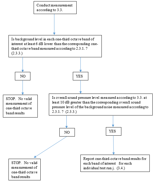
Figure 7a
Test procedures for measurement of frequency shift

Figure 7b
Test procedures for measurement of frequency shift, Method A
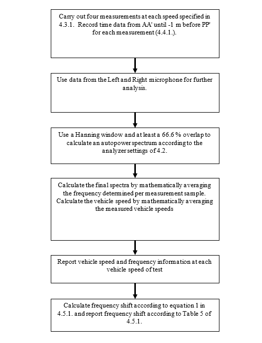
Figure 7c
Test procedures for measurement of frequency shift, Methods B, C, D, and E
