APPENDIX A
Agreement
Concerning the Adoption of Harmonized Technical United Nations Regulations for Wheeled Vehicles, Equipment and Parts which can be Fitted and/or be Used on Wheeled Vehicles and the Conditions for Reciprocal Recognition of Approvals Granted on the Basis of these United Nations Regulations[*]
(Revision 3, including the amendments which entered into force on 14 September 2017)
Addendum 157 – UN Regulation No. 158
Date of entry into force as an annex to the 1958 Agreement: 10 June 2021
Incorporating by the Department of Infrastructure, Transport, Regional Development, Communications and the Arts:
Supplement 1 to the original version of the Regulation – Date of entry into force: 22 June 2022
UN Regulation on uniform provisions concerning the approval of devices and motor vehicles with regard to the driver’s awareness of vulnerable road users behind vehicles

UNITED NATIONS
UN Regulation No. 158
UN Regulation on uniform provisions concerning the approval of devices and motor vehicles with regard to the driver’s awareness of vulnerable road users behind vehicles when reversing
Contents
Regulation
1. Scope
I. Devices for means of rear visibility
2. Definitions
3. Application for approval
4. Markings
5. Approval
6. Requirements
7. Modification of the type of device for means of rear visibility and extension of approval
8. Conformity of production
9. Penalties for non conformity of production
10. Production definitively discontinued
11. Names and addresses of Technical Services responsible for conducting approval tests, and of Type Approval Authorities
II. Installation of means of rear visibility or detection
12. Definitions
13. Application for approval
14. Approval
15. Requirements
16. Requirements for rear-view camera system
17. Requirements for detection systems
18. Modifications of the vehicle type and extension of approvals
19. Conformity of production
20. Penalties for non-conformity of protection
21. Production definitively discontinued
22. Names and addresses of Technical Services responsible for conducting approval tests, and of Type Approval Authorities
Annexes
1 Information document for type approval of a device for means of rear visibility
2 Information document for type approval of vehicle with respect to the installation of means of rear visibility or detection
3 Communication concerning the approval or refusal or extension or withdrawal of approval or production definitively discontinued of a type of device (Separate Technical Unit) for means of rear visibility, pursuant to Regulation No. 158
4 Communication concerning the approval or refusal or extension or withdrawal of approval or production definitively discontinued of a type of vehicle with regard to means of rear visibility or detection, pursuant to Regulation No. 158
Appendix
5 Arrangement of approval mark for a device for means of rear visibility
6 Test method for determining reflectivity
7 Procedure for determining the radius of curvature "r" of the reflecting surface of a mirror
8 Procedure for determining the "H" point and the actual torso angle for seating positions in motor vehicles
Appendix 1 - Description of the three-dimensional "H" point machine (3-D H machine)
Appendix 2 - Three-dimensional reference system
Appendix 3 - Reference data concerning seating positions
9 Test methods for close-proximity rear-view field of vision
10 Test methods for detection systems
Introduction (for information)
The purpose of this Regulation is to provide the provisions for means of rear visibility and detection that would improve the driver’s awareness of vulnerable road users behind vehicles when reversing. UN Regulation No. 46. provides the provisions for indirect vision of motor vehicles. This Regulation expands driver’s awareness behind vehicles when reversing. Therefore, some requirements of this Regulation may be satisfied by devices complying with UN Regulation No.46.
This Regulation cannot cover all the traffic conditions and infrastructure features in the type approval process; this Regulation recognises that the performances required in this Regulation cannot be achieved in all conditions (vehicle speed and condition, weather conditions, and traffic scenarios etc. may affect the system performances).
1. Scope
This Regulation applies to:
1.1. Approval of devices for means of rear visibility defined in Part I intended to be fitted to vehicles of category M and N.
1.2. Approval of vehicle installation of means of rear visibility or detection defined in Part II if fitted to vehicles of category M and N.
1.3. At the request of the manufacturer, Contracting Parties may grant approvals under Parts I and II to vehicles of other categories and devices for fitting to such vehicles.
1.4. The following vehicles of category M and N shall be exempted from this Regulation:
Vehicles where installation of means of rear visibility or detection is incompatible with their on-road use may be partly or fully exempted from this Regulation, subject to the decision of the Type Approval Authority.
1.5. If a vehicle has multiple device(s), the manufacturer shall designate the device that meets the provisions of the regulation.
Part I Devices for means of rear visibility
2. Definitions
For the purposes of this Regulation:
2.1. "Devices for means of rear visibility or detection" means devices intended, when reversing, to give a clear view of the rear of the vehicle within the fields of vision defined in paragraph 15.2. or intended to detect objects in the field of detection defined in paragraph 15.3.
These can be conventional mirrors, Rear-View Camera System, detection systems or other devices.
2.1.1. "Close-proximity rear-view device" means a device that gives the field of vision defined in paragraph 15.2. of this Regulation.
2.1.2. "Devices for means of rear visibility" means devices that present information of the fields of vision defined in paragraph 15.2.
2.1.2.1. “Rear-View Camera system (RVCS)” means any system intended to render an image of the outside world and give a clear view to the rear of the vehicle within the fields of vision defined in paragraph 15.2. by means of camera.
2.1.2.1.1. "Luminance contrast" means the brightness ratio between an object and its immediate background/surrounding that allows the object to be distinguished from its background/surroundings. The definition is in accordance with the definition given in ISO 9241-302:2008.
2.1.2.1.2. "Resolution" means the smallest detail that can be discerned with a perceptual system, i.e. perceived as separate from the larger whole. The resolution of the human eye is indicated as "visual acuity".
2.1.2.1.3. "Visual spectrum" means light with a wavelength within the range of the perceptual limits of the human eyes: 380‑780 nm.
2.1.2.2. "Close-proximity rear-view mirror" means any device, excluding devices such as periscopes, intended to give a clear view to the rear of the vehicle within the fields of vision defined in paragraph 15.2. by means of a reflective surface.
2.1.2.2.1. "r" means the average of the radii of curvature measured over the reflecting surface, in accordance with the method described in Annex 7.
2.1.2.2.2. "The principal radii of curvature at one point on the reflecting surface (ri)" means the values obtained with the apparatus defined in Annex 7, measured on the arc of the reflecting surface passing through the centre of this surface parallel to the segment b, as defined in paragraph 6.1.2.1.2. of this Regulation and on the arc perpendicular to this segment.
2.1.2.2.3. "The radius of curvature at one point on the reflecting surface (rp)" means the arithmetical average of the principal radii of curvature ri and r'i, i.e.:

2.1.2.2.4. "Spherical surface" means a surface, which has a constant and equal radius in all directions.
2.1.2.2.5. "Aspherical surface" means a surface, which has only in one plane a constant radius.
2.1.2.2.6. "Aspherical mirror" means a mirror composed of a spherical and an aspherical part, in which the transition of the reflecting surface from the spherical to the aspherical part has to be marked. The curvature of the main axis of the mirror is defined in the x/y coordinate system defined by the radius of the spherical primary calotte with:

Where:
R: nominal radius in the spherical part
k: constant for the change of curvature
a: constant for the spherical size of the spherical primary calotte
2.1.2.2.7. "Centre of the reflecting surface" means the centre of the visible area of the reflecting surface.
2.1.2.2.8. "The radius of curvature of the constituent parts of the mirror" means the radius "c" of the arc of the circle which most closely approximates to the curved form of the part in question.
2.1.2.3. "Other devices for means of rear visibility" means devices as defined in paragraph 2.1.2. above, where the field of vision is not obtained by means of a mirror or a Rear-View Camera System.
2.1.3. "Test object" means a cylindrical object with a height of 0.8 m and a diameter of 0.30 m.
2.1.4. "Field of vision" means the section of the tri-dimensional space above ground level which is monitored with the help of a device for indirect vision. Unless otherwise stated, this is based on the view offered by a device and/or devices other than mirrors. This may be limited by the relevant detection distance corresponding to the test object.
2.1.5. "Detection System" means a system which uses signals to enable the driver to detect objects in the area adjacent to the vehicle.
2.1.5.1. "Audible information" means information using auditory signals provided by a detection system as defined in paragraph 2.1.5. above to enable the driver to detect objects in the area adjacent to the vehicle.
2.1.5.2. "Optical information" means information using optical signals provided by a detection system as defined in paragraph 2.1.5. above to enable the driver to detect objects in the area adjacent to the vehicle.
2.1.5.3. "Haptic information" means information using haptic signals provided by a detection system as defined in paragraph 2.1.5. above to enable the driver to detect objects in the area adjacent to the vehicle.
2.1.6. "Field of detection" means the section of the tri-dimensional space above ground level which is monitored with the help of a detection system.
2.2. "Type of device for means of rear visibility or detection" means devices that do not differ on the following essential characteristics:
(a) Design of the device inclusive, if pertinent, the attachment to the bodywork;
(b) In the case of mirrors, the shape, the dimensions and radius of curvature of the mirror's reflecting surface;
(c) In the case of Rear-View Camera System, the field of view, the magnification.
(d) In the case of detection systems, the sensor type, the information signal type.
3. Application for approval
3.1. The application for approval of a type of device for means of rear visibility shall be submitted by the holder of the trade name or mark or by his duly accredited representative.
3.2. A model of information document is shown in Annex 1.
3.3. For each type of device for means of rear visibility the application shall be accompanied by three samples of the parts.
4. Markings
4.1. The samples of devices for means of rear visibility submitted for approval shall bear the trade name or mark of the manufacturer; this marking shall be clearly legible and be indelible.
4.2. Every device for means of rear visibility shall possess, on at least one of the main components, a space large enough to accommodate the approval mark, which shall be legible; this space shall be shown on the drawings referred to in Annex 1. The approval mark shall also be legible when the device is mounted on the vehicle. Other components of the device shall bear a means of identification. In the case of limited space for the approval mark(s), other means of identification that link it to the approval mark shall be provided.
5. Approval
5.1. If the samples submitted for approval meet the requirements of paragraph 6. of this Regulation, approval of the pertinent type of device for means of rear visibility shall be granted.
5.2. An approval number shall be assigned to each type approved. Its first two digits (at present 00) shall indicate the series of amendments incorporating the most recent major technical amendments made to the Regulation at the time of issue of the approval. The same Contracting Party shall not assign the same number to another type of device for means of rear visibility.
5.3. Notice of approval or of refusal or of extension or withdrawal of approval or of production definitively discontinued of a type of device for means of rear visibility pursuant to this Regulation shall be communicated to the Parties to the Agreement which apply this Regulation by means of a form conforming to the model in Annex 3 to this Regulation.
5.4. There shall be affixed, on at least one of the main components, conspicuously and in the space referred to in paragraph 4.2. above, to every device for means of rear visibility, conforming to a type approved under this Regulation, in addition to the mark prescribed in paragraph 4.1. above, an international approval mark consisting of:
5.4.1. A circle surrounding the letter "E" followed by:
(a) The distinguishing number of the country which has granted approval; and
(b) The number of this Regulation, followed by the letter "R", a dash and the approval number.
5.5. The approval mark and the additional symbol(s) shall be clearly legible and be indelible.
5.6. Annex 5 to this Regulation gives an example of the arrangement of the aforesaid approval mark and additional symbol.
6. Requirements
6.1. Close-proximity rear-view mirrors
6.1.1. General specifications
6.1.1.1. All mirrors may be adjustable.
6.1.2. Special specifications
6.1.2.1. Dimensions
6.1.2.1.1. The contours of the reflecting surface shall be of simple geometric form and its dimensions such that the mirror provides the field of vision specified in paragraph 15.2. of this Regulation.
6.1.2.1.2. The dimensions of the reflecting surface shall be such that it is possible to inscribe therein:
(a) A rectangle 40 mm high the base length of which, measured in millimeters, has the value "a";
(b) A segment which is parallel to the height of the rectangle and the length of which, expressed in millimeters, has the value "b".
6.1.2.2. Reflecting surface and coefficients of reflection
6.1.2.2.1. The reflecting surface of a mirror shall be either flat or spherically convex. Exterior mirrors may be equipped with an additional aspherical part provided that the main mirror fulfils the requirements of the indirect field of vision.
6.1.2.2.2. Differences between the radii of curvature of mirrors
6.1.2.2.2.1. The difference between ri or r'i, and rp at each reference point shall not exceed 0.15 r.
6.1.2.2.2.2. The difference between any of the radii of curvature (rp1, rp2, and rp3) and r shall not exceed 0.15 r.
6.1.2.2.2.3. When r is not less than 3,000 mm, the value of 0.15 r quoted in paragraphs 6.1.2.2.2.1. and 6.1.2.2.2.2. above is replaced by 0.25 r.
6.1.2.2.3. The value of the normal coefficient of reflection, as determined according to the method described in Annex 6, shall be not less than 40 per cent.
In the case of reflecting surfaces with a changeable degree of reflection, the "day" position shall allow the colours of the signals used for road traffic to be recognized. The value of the normal coefficient of reflection in the "night" position shall be not less than 4 per cent.
6.1.2.2.4. The reflecting surface shall retain the characteristics laid down in paragraph 6.1.2.2.3. above in spite of prolonged exposure to adverse weather conditions in normal use.
7. Modification of the type of device for means of rear visibility and extension of approval
7.1. Every modification to an existing type of device for means of rear visibility including its connection to the bodywork shall be notified to the Type Approval Authority which approved the type of device for means of rear visibility. The Type Approval Authority shall then either:
(a) Decide, in consultation with the manufacturer, that a new type-approval is to be granted; or
(b) Apply the procedure contained in paragraph 7.1.1. (Revision) and, if applicable, the procedure contained in paragraph 7.1.2. (Extension).
7.1.1. Revision
When particulars recorded in the information folder have changed and the Type Approval Authority considers that the modifications made are unlikely to have an appreciable adverse effect and that in any case the device for means of rear visibility still complies with the requirements, the modification shall be designated a "revision".
In such a case, the Type Approval Authority shall issue the revised pages of the information folder as necessary, marking each revised page to show clearly the nature of the modification and the date of re-issue. A consolidated, updated version of the information folder, accompanied by a detailed description of the modification, shall be deemed to meet this requirement.
7.1.2. Extension
The modification shall be designated an "extension" if, in addition to the change of the particulars recorded in the information folder;
(a) Further inspections or tests are required; or
(b) Any information on the communication document (with the exception of its attachments) has changed; or
(c) Approval to a later series of amendments is requested after its entry into force.
7.2. Confirmation or refusal of approval, specifying the alterations shall be communicated by the procedure specified in paragraph 5.3. above to the Parties to the Agreement which apply this Regulation. In addition, the index to the information package, attached to the communication document, shall be amended accordingly to show the date of the most recent revision or extension.
7.3. The Type Approval Authority issuing the extension of approval shall assign a series number to each communication form drawn up for such an extension.
8. Conformity of production
8.1. The conformity of production procedure shall comply with those set out in the Agreement, Schedule 1 (E/ECE/TRANS/505/Rev.3).
8.2. Every device for means of rear visibility approved under this Regulation shall be so manufactured as to conform to the type approved by meeting the requirements set out in paragraph 6. above.
9. Penalties for non‑conformity of production
9.1. The approval granted in respect of a type of device for means of rear visibility pursuant to this Regulation may be withdrawn if the requirement laid down in paragraph 8.1. above is not complied with or if the type of device for means of rear visibility did not satisfy the requirements prescribed in paragraph 8.2. above.
9.2. If a Contracting Party to the Agreement which applies this Regulation withdraws an approval it has previously granted, it shall forthwith so notify the other Contracting Parties applying this Regulation by means of a copy of the communication form bearing at the end, in large letters, the signed and dated annotation "APPROVAL WITHDRAWN".
10. Production definitively discontinued
If the holder of the approval completely ceases to manufacture a type of device for means of rear visibility approved in accordance with this Regulation, he shall so inform the Type Approval Authority which granted the approval. Upon receiving the relevant communication, the Authority shall inform thereof the other Parties to the Agreement applying this Regulation by means of a copy of the approval form bearing at the end, in large letters, the signed and dated annotation "PRODUCTION DISCONTINUED".
11. Names and addresses of Technical Services responsible for conducting approval tests, and of Type Approval Authorities
The Contracting Parties to the Agreement applying this Regulation shall communicate to the United Nations Secretariat the names and addresses of the Technical Services responsible for conducting approval tests and of the Type Approval Authorities which grant approval and to which forms certifying approval or refusal or extension or withdrawal of approval, issued in other countries, are to be sent.
Part IIInstallation of means of rear visibility or detection
12. Definitions
For the purpose of this Regulation:
12.1. "The driver's ocular points" means two points 65 mm apart and 635 mm vertically above point R of the driver's seat as defined in Annex 8. The straight line joining these points runs perpendicular to the vertical longitudinal median plane of the vehicle. The centre of the segment joining the two ocular points is in a vertical longitudinal plane which shall pass through the centre of the driver's designated seating position, as specified by the vehicle manufacturer.
12.2. "Ambinocular vision" means the total field of vision obtained by the superimposition of the monocular fields of the right eye and the left eye (see Figure 2 below).
Figure 2
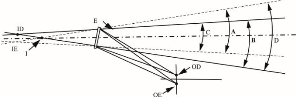
E = interior rear-view mirror
OD = driver’s eyes
OE = driver’s eyes
ID = virtual monocular images
IE = virtual monocular images
I = virtual ambinocular image
A = angle of vision of left eye
B = angle of vision of right eye
C = binocular angle of vision
D = ambinocular angle of vision
12.3. "Type of vehicle as regards to the driver’s awareness of vulnerable road users behind vehicles" means motor vehicles which are identical in respect of the following basic features:
12.3.1. Type of means of rear visibility or detection;
12.3.2. The bodywork features which reduce the field of vision;
12.3.3. The coordinates of point R (where applicable);
12.3.4. The prescribed positions, and type-approval markings of compulsory and (if fitted) optional devices for indirect vision.
12.4. "Vehicles of categories M1, M2, M3, N1, N2 and N3" means those defined in the Consolidated Resolution on the Construction of Vehicles (R.E.3), (document ECE/TRANS/WP.29/78/Rev.6).
12.5. "Ocular reference point" means the middle point between the driver's ocular points.
12.6. "Backing event" means an amount of time from start and ends of reversing motion as described in 15.1.1. in this Regulation.
12.7. "The driver's looking-back ocular points" means two points located at 96 mm longitudinally rearward, 158 mm horizontally inside to vehicle centre direction and 6 mm vertically above from "the driver's ocular points" described in paragraph 12.1.
12.8. "Active vehicle mode" means the vehicle mode when:
The powertrain moves the vehicle, on release of the brake system and in some cases by application of pressure to the accelerator pedal (or activation of an equivalent control).
12.9. "Type of means of rear visibility or detection " means rear visibility or detection means that do not differ on the following essential characteristics:
(a) The type of devices of means of rear visibility or detection;
(b) The mean of rear visibility or detection;
13. Application for approval
13.1. The application for approval of a vehicle type with regard to the installation of means of rear visibility or detection shall be submitted by the vehicle manufacturer or by his duly accredited representative.
13.2. A model of information document is shown in Annex 2.
13.3. A vehicle representative of the vehicle type to be approved shall be submitted to the Technical Service responsible for conducting the approval tests.
13.4. The Type Approval Authority shall verify the existence of satisfactory arrangements for ensuring effective checks on conformity of production before type‑approval is granted.
13.5. The RVCS shall be provided by the applicant with the following documents:
(a) Technical specification of the RVCS;
(b) Operator's manual.
14. Approval
14.1. If the vehicle type submitted for approval in accordance with paragraph 13. above meets the requirements of paragraph 15. of this Regulation, approval shall be granted.
14.2. An approval number shall be assigned to each type approved. Its first two digits (at present 00) shall indicate the series of amendments incorporating the most recent or technical amendments made to the Regulation at the time of issue of the approval. The same Contracting Party shall not assign the same number to another vehicle type.
14.3. Notice of approval or of refusal or of extension or withdrawal of approval of a vehicle type pursuant to this Regulation shall be communicated to the Parties to the Agreement which apply this Regulation by means of a form conforming to the model in Annex 4 to this Regulation.
15. Requirements
15.1. General
For the purpose of this Regulation, the vehicle shall fulfil the following requirements:
During a backing event at least one means of rear visibility or detection shall be provided to the driver.
Means of rear visibility provide a close-proximity rear-view field of vision as defined in paragraph 15.2 below. Possible means are:
(a) Direct vision,
(b) Devices approved to UN Regulation No. 46,
(c) Close Proximity Rear-view Mirror complying with this Regulation,
(d) Rear-View Camera System complying with this Regulation.
Means of detection provide an information other than vision for field of detection as defined in paragraphs 15.3 below. Possible means are:
(a) Detection System complying with this Regulation.
15.1.1. Backing event starts when the vehicle is in Active vehicle mode and the vehicle's direction selector is placed from forward, park or neutral into reverse by the driver or a system, and ends when one of the following forward motion conditions, at the manufacturer's choosing, is met:
(a) A speed ≤ 16 km/h (including 0 km/h), or
(b) A distance travelled ≤ 10 meters (including 0 meters), or
(c) A continuous duration ≤ 10 seconds (including 0 seconds), or
(d) The vehicle's direction selector is not placed in reverse.
15.1.2. The requirements in paragraph 15. shall not apply during a remote control manoeuvring and a remote controlled parking as defined in UN Regulation No. 79.
15.2. Close Proximity Rear-View Field of Vision
The field of vision shall be bounded by the following planes:
(a) A transverse vertical plane passing through a point 0.3m from the outermost point of the rear of the vehicle;
(b) A transverse vertical plane passing through a point 3.5m behind the outermost point of the rear of the vehicle;
(c) Two longitudinal vertical planes parallel to the longitudinal vertical median plane passing through the outermost point of each side of the vehicle.
The height of the field of vision is defined at nine positions within the boundaries of the field of vision with test objects with a height of 0.8m and a diameter of 0.3m which are located on the ground plane as defined in Figure 3 below:
Figure 3
Close-proximity rear-view field of vision

15.2.1. Requirements
When tested under the conditions defined in Annex 9 the requirement for close-proximity rear-view field of vision shall be considered to be satisfied if the defined field of vision can be seen:
(a) For the test objects in the first row (Test objects A, B, and C):
A 0.15 m x 0.15 m area or the top of the test object shall be visible at least one position on each test object.
(b) For the test objects in the second row (Test objects D, E, and F) and the third row (Test objects G, H, and I);
The whole test object shall be seen.
15.2.1.1. Via the direct view from the driver’s looking back ocular points; or
15.2.1.2. Via the direct view from the driver’s looking back ocular points combined with a close-proximity rear-view mirror installed at the rear end of the vehicle supporting this direct view; or
15.2.1.3. Via a device of indirect vision (mirror or CMS or other) approved to UN Regulation No. 46; or
15.2.1.4. Via a means of rear visibility (mirror or RVCS or other) complying with this Regulation; or
15.2.1.5. Via a device of detection system that complies with this Regulation except for the field of detection (e.g. very short range); or
15.2.1.6. Via a combination of devices of paragraphs 15.2.1.3, 15.2.1.4. and 15.2.1.5. except a combination of RVCS and mirror(s) or close-proximity rear-view mirror.
15.2.1.7. The options 15.2.1.1 and 15.2.1.2 only apply to the vehicle categories M1 and N1, when the distance between looking back ocular point to vehicle rear-end does not exceed 2000 mm and when the vehicle has one seating row.
15.2.2. The close-proximity rear-view field of vision shall be established using ambinocular vision, the eyes being at the "driver's ocular points" as defined in paragraph 12.1. above. The fields of vision shall be determined when the vehicle is in running order as defined in the consolidated Resolution on the Construction of vehicles (R.E.3) (ECE/TRANS/WP.29/78/Rev.6, para. 2.2.5.4.), plus for M1 and N1 vehicles one front seat passenger (75 kg). When established through windows, the glazing shall have a total light transmission factor in accordance with UN Regulation No. 43, Annex 24.
In case of direct view from the driver’s looking back ocular points the vertical position of rear seat headrests shall be set at the designed position of assumed to use or the highest position if the headrest has multiple position settings or at the position agreed with the Technical Service.
15.2.3. In the case of a combination of means of rear visibility or detection, each entire transverse row of test objects shall be seen by one of these means. The close-proximity rear-view field of vision shall be obtained from the minimum number of mirrors and monitors.
15.2.4. In the case of mirrors consisting of several reflecting surfaces which are either of different curvature or make an angle with each other, at least one of the reflecting surfaces shall provide the field of vision and have the dimensions specified for the class to which they belong.
15.3. Field of detection
The field of detection shall be bounded by the following planes (see figure 4):
(a) A transverse vertical plane passing through a point 200 mm from the outermost point of the rear of the vehicle;
(b) A transverse vertical plane passing through a point 1,000 mm behind the outermost point of the rear of the vehicle;
(c) Two longitudinal vertical planes parallel to the longitudinal vertical median plane passing through the outermost point of each side of the vehicle.
Figure4
Field of detection

15.3.1. When tested under the conditions defined in Annex 10 the requirement for field of detection shall be considered to be satisfied if the information as defined in paragraph 17.2 is provided to the driver.
15.4. Devices for reversing motion
15.4.1. Position
15.4.1.1. Devices for means of rear visibility or detection shall be so placed that the driver, when sitting on the driving seat in a normal driving position, has a clear view of the road to the rear, side(s) or front of the vehicle.
15.4.1.2. In the case of any vehicle, which is in chassis/cab form when the field of vision or detection is measured, the minimum and maximum body widths, heights and lengths shall be stated by the manufacturer and, if necessary, simulated by dummy headboards. All vehicles and devices for means of rear visibility or detection configurations taken into consideration during the tests shall be shown on the type-approval certificate for a vehicle with regard to the installation of devices for means of rear visibility or detection (see Annex 4). This includes information related to a range of device installation positions (in length, width and height).
15.4.1.3. Devices for means of rear visibility or detection shall not project beyond the external bodywork of the vehicle substantially more than is necessary to comply with the requirements concerning fields of vision or fields of detection.
15.4.1.4. Devices for means of rear visibility or detection shall be fitted in such a way that the devices do not move so as significantly to change the field of vision or detection as measured or vibrate to an extent which would cause the driver to misinterpret the nature of the image perceived.
16. Requirements for rear-view camera system
16.1. Default view
In default view the RVCS shall show the field of view at least as defined in paragraph 15.2.
The RVCS must default to the rear-view image at the beginning of each backing event regardless of any modifications to the field of view that the driver has previously selected.
16.1.1. Object size
When the Rear-view image is measured in accordance with the paragraphs 3. of Annex 9, the calculated visual angle subtended by the horizontal width of:
(a) All three test objects at the last row specified in 15.2 shall average not less than 5 minutes of arc; and
(b) Each individual test object shall not be less than 3 minutes of arc.
16.1.1.1. Luminance and contrast adjustment
If manual adjustment is provided, the operator's manual shall provide information on how to change the luminance/contrast.
16.1.1.2. Overlay requirements within the required field of vision
Overlays shall display only rearward driving-related visual information or safety-related information. Overlays for other purposes of information in the required field of vision are not allowed.
Manually activated overlays are allowed, only when the driver needs to activate a rearward driving-related function or safety-related function (e.g. cleaning of the lens or activation of trailer hitch view) or requires specific information in such an environment. The driver may have an option to close the overlay.
16.1.1.3. Deactivation
The rear-view image shall remain visible during the backing event until either, the driver modifies the view, or the vehicle direction selector is no longer in the reverse position or the backing event is finished.
Modifying the view means to switch to any other camera views.
The view can be manually switched off when the vehicle is not moving rearward.
The system may be switched off when the vehicle detects a coupling by means of a coupling device.
16.1.1.4. Automatic change of view
When there is a risk of collision, the field of view may change and focus on the collision area. It shall be demonstrated to the Technical Service that this change of view increases the safety.
When the vehicle is not driving straight, the field of view may change following the vehicle trajectory.
16.1.2. Operating readiness (System availability)
Non-operation of the system shall be recognizable to the driver (e.g. RVCS failure by, i.e. warning indication, display information, black screen, absence of status indicator). The information for the driver shall be explained in the operator's manual.
16.1.2.1. Response time
The rear-view image meeting the requirements described in 15.2. shall be provided within a maximum of 2.0 seconds after start of the backing event, when tested according to paragraphs 2. of Annex 9.
16.1.3. Monitor inside the vehicle
16.1.3.1. The monitor defined size shall be visible without any obstruction from the ocular reference point. A virtual testing is acceptable.
16.1.4. Obstruction of the driver's direct view caused by the installation of a device for indirect vision shall be restricted to a minimum.
16.2. Vehicles may be equipped with additional devices for indirect vision.
16.3 Notwithstanding the provisions above, any other design concept shall be demonstrated to the satisfaction of the Technical Service within the safety concept that is provided in the provisions above.
16.4 The effectiveness of the RVCS shall not be adversely affected by magnetic or electrical fields. This shall be demonstrated by compliance with the technical requirements and transitional provisions of UN Regulation No. 10, 05 series of amendments or any later series of amendments.
17. Requirements for detection systems
17.1. System activation
The system shall be activated when the backing event starts. If proper functioning cannot be effected, either the system shall automatically shut off or the driver shall be able to deactivate the system manually.
The detection system shall remain active as long as either the vehicle direction selector is in the reverse position or the backing event is not ended.
In case the vehicle can detect coupling with a coupling device, the system may be switched off.
17.2. Driver interface and information presentation strategy
17.2.1. The system shall have at least two kinds of information signal selected from audible, optical, and haptics.
17.2.1.1. As long as one information signal remains active, the driver may de-activate the other information signals.
17.2.2. Audible information
When an object is detected in the rear horizontal area as described in paragraph 1.3. of Annex 10. while the reverse gear is selected/engaged, audible information in accordance with ISO 15006:2011 shall be given.
In presenting audible information, the distance to the target may be identified by two or more acoustic signals. These acoustic signals, differentiating distances and detection widths, may be indicated by changing the frequency of the intermittent sound. A faster intermittent sound or continuous sound shall be used as the distance becomes closer.
17.2.3. Duration of signalling
Signalling for an object shall last as long as the object is detected and shall end when the object is no longer detected or when the system is deactivated.
To reduce the driver's discomfort, the audible signal can be automatically suspended temporarily after a certain time set by the manufacturer has elapsed, provided that the system remains activated. If, while the audible signal is automatically suspended temporarily, the distance to the object becomes shorter, the audible signal shall be automatically resumed. If the distance to the object becomes longer, the audible signal may remain suspended.
17.2.4. Optical information
In the case optical information is placed on a monitor used for other information such as meter cluster display or other displays, overlay is allowed and shall comply with the overlay requirements of the RVCS in 16.1.1.2. of this Regulation.
17.2.5. Operating readiness (System availability)
Non-operation of the system shall be recognizable to the driver (e.g. Detection system failure by, i.e. warning indication, display information, black screen, absence of status indicator). The information for the driver shall be explained in the operator's manual.
17.3. Performance of object detection
17.3.1. Response time
At least one of the audible or haptic information signals that meets the requirements as described in 17.2., shall be given to the driver within a maximum of 0.6 seconds after the start of the backing event, when tested according to paragraph 2. of Annex 10.
17.4 The effectiveness of the detection system shall not be adversely affected by magnetic or electrical fields. This shall be demonstrated by compliance with the technical requirements and transitional provisions of UN Regulation No. 10, 05 series of amendments or any later series of amendments.
18. Modifications of the vehicle type and extension of approval
18.1. Every modification of the vehicle type shall be notified to the Type Approval Authority which approved the vehicle type. Type Approval Authority shall then either:
(a) Decide, in consultation with the manufacturer, that a new type approval is to be granted; or
(b) Apply the procedure contained in paragraph 18.1.1. (Revision) and, if applicable, the procedure contained in paragraph 18.1.2. (Extension).
18.1.1. Revision
When particulars recorded in the information folder have changed and the Type Approval Authority considers that the modifications made are unlikely to have an appreciable adverse effect, and that in any case the vehicle still complies with the requirements, the modification shall be designated a "revision".
In such a case, the Type Approval Authority shall issue the revised pages of the information folder as necessary, marking each revised page to show clearly the nature of the modification and the date of re-issue. A consolidated, updated version of the information folder, accompanied by a detailed description of the modification, shall be deemed to meet this requirement.
18.1.2. Extension
The modification shall be designated an "extension" if, in addition to the change of the particulars recorded in the information folder,
(a) Further inspections or tests are required; or
(b) Any information on the communication document (with the exception of its attachments) has changed; or
(c) Approval to a later series of amendments is requested after its entry into force.
18.2. Confirmation or refusal of approval, specifying the alterations, shall be communicated to the Parties to the Agreement which apply this Regulation by means of a form conforming to the model in Annex 4 to this Regulation. In addition, the index to the information package, attached to the communication document, shall be amended accordingly to show the date of the most recent revision or extension.
18.3. The Type Approval Authority issuing the extension of approval shall assign a series number to each communication form drawn up for such an extension.
19. Conformity of production
19.1. The conformity of production procedure shall comply with those set out in the Agreement, Schedule 1 (E/ECE/TRANS/505/Rev.3).
19.2. Every vehicle approved under this Regulation shall be so manufactured as to conform to the type approved by meeting the requirements set out in paragraph 15., where applicable paragraph 16. and paragraph 17. above.
20. Penalties for non‑conformity of production
20.1. The approval granted in respect of a vehicle type pursuant to this Regulation may be withdrawn if the requirement laid down in paragraph 19.1. above is not complied with or if the vehicle fails to pass the checks prescribed in paragraph 19.2. above.
20.2. If a Party to the Agreement which applies this Regulation withdraws an approval it has previously granted, it shall forthwith so notify the other Contracting Parties applying this Regulation by means of a copy of the approval form bearing at the end, in large letters, the signed and dated annotation "APPROVAL WITHDRAWN".
21. Production definitively discontinued
If the holder of the approval completely ceases to manufacture a type of vehicle approved in accordance with this Regulation, he shall so inform the Type Approval Authority which granted the approval. Upon receiving the relevant communication, the Authority shall inform thereof the other Parties to the Agreement applying this Regulation by means of a copy of the approval form bearing at the end, in large letters, the signed and dated annotation "PRODUCTION DISCONTINUED".
22. Names and addresses of Technical Services responsible for conducting approval tests, and of Type Approval Authorities
The Parties to the Agreement applying this Regulation shall communicate to the United Nations Secretariat the names and addresses of the Technical Services responsible for conducting approval tests and of the Type Approval Authorities which grant approval and to which forms certifying approval or refusal or extension or withdrawal of approval, issued in other countries, are to be sent.
Annex 9
Test methods for close-proximity rear-view field of vision
1. Field of vision
The requirements of field of vision defined in paragraphs 15.2. of this Regulation can be tested under the conditions described in this Annex.
1.1. Test objects
Each test object shall be a right circular cylinder that is 0.8 m high and 0.3 m in external diameter. Each test object shall be marked as follows.
(a) The test object shall have a painted patch measuring 0.15 m x 0.15 m that can be moved from the bottom to the top of the side of the cylinder.
(b) The painted patch shall be of a colour that contrasts with both the rest of the cylinder and the test surface.
Figure A
Test object

1.2. Test object locations and orientations
Place the test objects at the locations specified in (a) to (h) and illustrated in Figure B. Measure the distances shown in Figure B from a test object to another test object or other object from the cylindrical centre (axis) of the test object as viewed from above. Each test object shall be oriented so that its axis is vertical.
(a) Place test objects A, B, and C so that their centres are in a transverse vertical plane that is 0.3 m to the rear of a transverse vertical plane tangential to the rearmost surface of the vehicle.
(b) Place test object B so that its centre is in a longitudinal vertical plane passing through the vehicle's longitudinal centreline.
(c) Place test objects D, E, and F so that their centres are in a transverse vertical plane that is 1.5 m to the rear of a transverse vertical plane tangential to the rearmost surface of the vehicle.
(d) Place test object E so that its centre is in a longitudinal vertical plane passing through the vehicle's longitudinal centreline.
(e) Place test objects G, H, and I so that their centres are in a transverse vertical plane that is 3.35 m to the rear of a transverse vertical plane tangential to the rearmost surface of the vehicle.
(f) Place test object H so that its centre is in a longitudinal vertical plane passing through the vehicle's longitudinal centreline.
(g) Place test objects A, D, and G so that their outermosts are in a longitudinal vertical plane tangential to the left-side outermost surface of the vehicle.
(h) Place test objects C, F, and I so that their outermosts are in a longitudinal vertical plane tangential to the right-side outermost surface of the vehicle.
Mechanical coupling devices and luggage racks located on the rear of the vehicle shall be disregarded.
Figure B
Test object locations

1.3 Test conditions
1.3.1. Lighting.
The ambient illumination conditions in which testing is conducted consists of light that is evenly distributed from above and is at an intensity of between 7,000 lux and 10,000 lux, as measured at the centre of the exterior surface of the vehicle's roof.
1.3.2. Temperature.
The temperature inside the vehicle during test is any temperature between 15 °C and 25 °C,
1.3.3. Vehicle conditions.
1.3.3.1 Tires.
The vehicle's tires are set to the vehicle manufacturer's recommended cold inflation pressure.
1.3.3.2. Vehicle load.
The vehicle is in running order as defined in the consolidated Resolution on the Construction of vehicles (R.E.3) (ECE/TRANS/WP.29/78/Rev.6, paragraph 2.2.5.4.), plus for M1 and N1 vehicles one front seat passenger (75 kg).
1.3.3.3. Adjustable suspension
If the vehicle is equipped with adjustable suspension system, it shall be set at worst condition.
1.3.3.4. Rear hatch and trunk lids.
If the vehicle is equipped with rear hatches or trunk lids, they are closed and latched in their normal vehicle operating condition.
1.4. Test procedure
The visibility of each pole shall be tested one by one.
Optionally, one row can be tested at the same time. After successful pole identification, the pole can be removed.
The poles of the first row (A, B, C) may rotate direction in order to be visible the painted patch as much as possible.
2. System readiness
2.1. Test conditions
(a) The vehicle shall be left in a parked parking status until it is ensured that all electronic systems are de-activated; or for a minimum of 30 minutes.
(b) It is permissible for the test person or equipment to be already situated within the vehicle.
(c) Ensure the vehicle gear selector is not in reverse gear.
(d) The test may start with opening the driver door. Once the door is opened, it shall be closed again.
2.2. Test procedure
(a) Put the vehicle into the active vehicle mode. This action shall initiate/start the first timer.
(b) Wait for a minimum of 6 sec
(c) Start the backing event by selecting the reverse mode. If it is not possible to put the vehicle into reversing mode 6 sec after being put into active vehicle mode, the backing event shall be started as soon as technically possible.
(d) Initiate/start the second timer, in accordance with the manufacturer’s specification and no later than when the reverse mode or gear is engaged.
(e) Record the response time on second timer until the rear-view is completely visible on the display.
3. Object size
3.1 Test reference point.
Obtain the test reference point using the following procedure.
(a) Locate the centre of the forward-looking eye midpoint (Mf) illustrated in Figure C so that it is 635 mm vertically above the H point (H) and 96 mm aft of the H point.
(b) Locate the head/neck joint centre (J) illustrated in Figure C so that it is 100 mm rearward of Mf and 588 mm vertically above the H point. In the case of the head/neck joint centre (J) is not compatible for the vehicle seat configuration, adjust the driver's seat to the midpoint of the longitudinal adjustment range. If the seat cannot be adjusted to the midpoint of the longitudinal adjustment range, the closest adjustment position to the rear of the midpoint shall be used.
(c) Draw an imaginary horizontal line between Mf and a point vertically above J, defined as J2.
(d) Rotate the imaginary line about J2 in the direction of the rear-view image until the straight-line distance between Mf and the centre of the display used to present the rear-view image required in this standard reaches the shortest possible value.
(e) Define this new, rotated location of Mf to be Mr (eye midpoint rotated).
3.1. Measurement procedure.
(a) Locate a 35 mm or larger format still camera, video camera, or digital equivalent such that the centre of the camera's image plane is located at Mr and the camera lens is directed at the centre of the display's rear-view image.
(b) Affix a ruler at the base of the rear-view image in an orientation perpendicular with a test object cylinder centreline. If the vehicle head restraints obstruct the camera's view of the display, they may be adjusted or removed.
(c) Photograph the image of the visual display with the ruler included in the frame and the rear-view image displayed.
3.2. Extract photographic data.
(a) Using the photograph, measure the apparent length, of a 50 mm delineated section of the in-photo ruler, along the ruler's edge, closest to the rear-view image and at a point near the horizontal centre of the rear-view image.
(b) Using the photograph, measure the horizontal width of the upper portion of each of the three test objects located at positions G, H, and I in Figure B.
(c) Define the measured horizontal widths of the three test objects as dG, dH, and dI.
3.3. Obtain scaling factor.
Using the apparent length of the 50 mm portion of the ruler as it appears in the photograph, divide this apparent length by 50 mm to obtain a scaling factor. Define this scaling factor as scale.
3.4. Determine viewing distance.
Determine the actual distance from the rotated eye midpoint location (Mr) to the centre of the rear-view image. Define this viewing distance as aeye.
3.5. Calculate visual angle subtended by test objects.
Use the following equation to calculate the subtended visual angles:

where i can take on the value of either test object G, H, or I, and arcsine is calculated in units of degrees.
Figure C
Eye Midpoint location (Mf) in the mid-sagittal plane with respect to R point for forward-looking 50th percentile male driver seated with 25 degree seat back angle