This is the Radiocommunications (Unacceptable Levels of Interference — 26 GHz Band) Determination 2020.
This instrument commences at the start of the day after the day it is registered on the Federal Register of Legislation.
Note: The Federal Register of Legislation may be accessed free of charge at www.legislation.gov.au.
This instrument is made under subsection 145(4) of the Radiocommunications Act 1992.
(1) In this instrument:
26 GHz band means the part of the spectrum from 25.1 GHz to 27.5 GHz.
Act means the Radiocommunications Act 1992.
active antenna system or AAS means a base station antenna system where the amplitude and/or phase between antenna elements is continually adjusted, resulting in an antenna pattern that varies in response to short term changes in the radio environment.
ASMG means the Australian Spectrum Map Grid 2012, published by the ACMA on its website at www.acma.gov.au.
Note: The ASMG can be accessed for free on the ACMA’s website: www.acma.gov.au.
centre frequency, in relation to a radiocommunications transmitter, means the frequency midway between the lower and upper frequency limits of the transmitter’s occupied bandwidth.
DEM-3S means the dataset:
(a) with the citation “Gallant, J., Wilson, N., Tickle, P.K., Dowling, T., Read A. 2009. 3 Second SRTM Derived Digital Elevation Model (DEM) Version 1.0. Record 1.0. Geoscience Australia, Canberra”; and
(b) given the persistent identifier 69888;
containing modelled terrain height information for Australia, published by Geoscience Australia.
Note: Copies of DEM-3S can be obtained free of charge from the Geoscience Australia website: www.ga.gov.au.
device boundary, in relation to a radiocommunications transmitter or a group of radiocommunications transmitters operated under a spectrum licence, means the device boundary established in accordance with Part 1 of Schedule 2 to this instrument.
device boundary criterion, in relation to a radiocommunications transmitter or a group of radiocommunications transmitters operated under a spectrum licence, means the value of the mathematical expression calculated in accordance with Part 2 of Schedule 2 to this instrument.
EIRP, in relation to a radiocommunications device, means the Equivalent Isotropically Radiated Power of the device.
emission designator means the designation of a radiocommunications transmitter’s emission, determined in accordance with section 6.
fixed receiver means a radiocommunications receiver located at a fixed point on land or sea and not designed or intended for use while in motion.
fixed transmitter means a radiocommunications transmitter located at a fixed point on land or sea and not designed or intended for use while in motion.
GDA94 means the geodetic datum designated as the “Geocentric Datum of Australia (GDA)” gazetted in the Commonwealth of Australia Gazette No. GN 35 on 6 September 1995, as existing on that date.
Note: More information on GDA94 can be obtained free of charge from the Geoscience Australia website: www.ga.gov.au.
geographic area, for a spectrum licence, means the area within which the operation of a radiocommunications device is authorised under the licence.
group of radiocommunications receivers has the meaning given by section 8.
group of radiocommunications transmitters has the meaning given by section 7.
HCIS identifier means an identifier used to describe a geographical area in the HCIS.
hierarchical cell identification scheme or HCIS means the cell grouping hierarchy scheme used to describe areas in the ASMG.
horizontally radiated power, for a radiocommunications device, means the sum of:
(a) the maximum true mean power, in dBm per specified rectangular bandwidth, at the antenna connector that is located within the frequency band of the spectrum licence authorising the operation of the radiocommunications device; and
(b) the antenna gain relative to an isotropic antenna in a specified direction in the horizontal plane containing the phase centre of the antenna used with the radiocommunications device, in dBi.
ITU means the International Telecommunication Union.
ITU-R means the International Telecommunication Union Radiocommunication Sector.
location, in relation to a radiocommunications transmitter or group of radiocommunications transmitters, means the location of the transmitter or group of transmitters, as the case may be, calculated in accordance with Schedule 1 to this instrument.
maximum true mean power means the true mean power measured in a specified, rectangular bandwidth that is located within a specified frequency band, such that the true mean power is the maximum of true mean powers produced.
Note: The power within the specified rectangular bandwidth is normally established by taking measurements using either an adjacent channel power meter or a spectrum analyser. Estimation of the accuracy of the measuring equipment, measurement protocol and any adjustments made to measurements to take account of practical filter shape factors should be in accordance with good engineering practices.
mean power means the average power measured during an interval of time that is at least 10 times the period of the lowest modulation frequency.
occupied bandwidth, in relation to a radiocommunications transmitter, means the width of a frequency band having upper and lower limits that are necessary to contain 99% of the true mean power of the transmitter’s emission at any time.
Radio Regulations means the document:
(a) titled ‘Radio Regulations’; and
(b) published by the ITU.
Note 1: The Radio Regulations published by the ITU are not regulations made by the Governor‑General under the Act.
Note 2: Copies of the Radio Regulations can be obtained for free from the ITU website: www.itu.int.
Recommendation ITU-R P.525-4 means the ITU-R Recommendation “P.525-4 Calculation of free-space attenuation” published by the ITU.
Note: Copies of Recommendation ITU-R P.525-4 can be obtained for free from the ITU website: www.itu.int.
Recommendation ITU-R P.526-15 means the ITU-R Recommendation “P.526-15 Propagation by diffraction” published by the ITU.
Note: Copies of Recommendation ITU-R P.526-15 can be obtained for free from the ITU website: www.itu.int.
Recommendation ITU-R P.2108-0 means the ITU-R Recommendation “P.2108-0 Prediction of clutter loss” published by the ITU.
Note: Copies of Recommendation ITU-R P.2108-0 can be obtained for free from the ITU website: www.itu.int.
total radiated power, in relation to a radiocommunications transmitter, means the integral of the power transmitted in different directions over the entire radiation sphere. It is measured considering the combination of all radiating elements on an antenna panel or individual device.
true mean power means:
(a) if an unmodulated carrier is present – the mean power measured while the unmodulated carrier is present; and
(b) if an unmodulated carrier is not present – the mean power measured while transmitted information is present.
(2) In this instrument, unless otherwise specified, a reference to a part of the spectrum, a frequency band or a frequency range includes all frequencies that are greater than but not including the lower frequency, up to and including the higher frequency.
Note 1: A number of other expressions used in this instrument are defined in the Act, including the following:
- ACMA;
- core condition;
- frequency band;
- interference;
- radiocommunications device;
- radiocommunications receiver;
- radiocommunications transmitter;
- radio emission;
- Register;
- spectrum licence.
Note 2: Subsection (2) means the lower number in the reference to a part of the spectrum, a frequency band or a frequency range is not included in the part of the spectrum, the frequency band or the frequency range.
In this instrument, unless the contrary intention appears:
(a) a reference to any other legislative instrument is a reference to that other legislative instrument as in force from time to time; and
(b) a reference to any other kind of instrument or writing is a reference to that other instrument or writing as in force or existing from time to time.
Note 1: For references to Commonwealth Acts, see section 10 of the Acts Interpretation Act 1901; and see also subsection 13(1) of the Legislation Act 2003 for the application of the Acts Interpretation Act 1901 to legislative instruments.
Note 2: All Commonwealth Acts and legislative instruments are registered on the Federal Register of Legislation.
Note 3: See section 314A of the Act.
(1) For the purpose of this instrument, the designation of a radiocommunications transmitter’s emission (emission designator) is determined using the methods specified in the Radio Regulations.
(2) For the purpose of determining the emission designator of a radiocommunications transmitter using the methods specified in the Radio Regulations, references in the Radio Regulations to “necessary bandwidth” for a given class of emission are taken to be references to the occupied bandwidth of the transmitter.
Note: At the date of making this instrument, Appendix 1 of the Radio Regulations sets out the method to be used for determining the designation of a radiocommunications transmitter’s emission.
(1) For the purpose of this instrument, and subject to subsection (2), two or more fixed transmitters are a group of radiocommunications transmitters if:
(a) each transmitter has the same centre frequency and emission designator;
(b) each transmitter is operated for the purpose of communicating with the same radiocommunications receiver or group of radiocommunications receivers;
(c) each transmitter has an antenna of the same type, model and manufacturer;
(d) the antenna used with each fixed transmitter is located on the same structure and within 20 metres of the phase centre of all antennas within the group of radiocommunications transmitters; and
(e) the identification number assigned by the ACMA to the antenna used with each radiocommunications transmitter is the same.
Note: The Radiocommunications (Register of Radiocommunications Licences) Determination 2017 sets out the information that must be included about each radiocommunications device operated under a spectrum licence.
(2) A radiocommunication transmitter must not belong to more than one group of radiocommunications transmitters.
Note: If a radiocommunications transmitter is capable of belonging to more than one group of radiocommunications transmitters, the spectrum licensee or authorised third party may nominate which group the transmitter belongs to.
(1) For the purpose of this instrument, and subject to subsection (2), two or more fixed receivers are a group of radiocommunications receivers if:
(a) each receiver is operated for the purpose of receiving communication from the same radiocommunications transmitter or group of radiocommunications transmitters;
(b) each receiver has an antenna of the same type, model and manufacturer;
(c) the antenna used with each fixed receiver is located on the same structure and within 20 metres of the phase centre of all antennas within the group of radiocommunications receivers; and
(d) the identification number assigned by the ACMA to the antenna used with each radiocommunications receiver is the same.
Note: The Radiocommunications (Register of Radiocommunications Licences) Determination 2017 sets out the information that must be included about each radiocommunications device operated under a spectrum licence.
(2) A radiocommunication receiver must not belong to more than one group of radiocommunications receivers.
Note: If a radiocommunications receiver is capable of belonging to more than one group of radiocommunications receivers, the spectrum licensee or authorised third party may nominate which group the receiver belongs to.
(1) For the purpose of subsection 145(4) of the Act, a level of interference caused by a radiocommunications transmitter operated under a spectrum licence issued for the 26 GHz band is unacceptable if:
(a) the operation of the transmitter in the 26 GHz band results in a breach of a core condition of the licence relating to the maximum permitted level of radio emission from the transmitter:
(i) outside the parts of the spectrum the use of which is authorised under the licence; or
(ii) outside the geographic area of the licence; or
(b) subject to subsections (2), (3) and (4), any part of the device boundary of the transmitter lies outside of the geographic area of the licence; or
(c) the device boundary of the transmitter cannot be calculated in accordance with Part 1 of Schedule 2 to this instrument.
(2) A level of interference mentioned in paragraph (1)(b) is not unacceptable in relation to a part of the device boundary that:
(a) lies outside the boundary of the ASMG; and
(b) is connected to a radial that:
(i) is mentioned in Part 1 of Schedule 2 to this instrument; and
(ii) does not cross the geographic area of another spectrum licence in the 26 GHz band.
(3) A level of interference mentioned in paragraph (1)(b) is not unacceptable in relation to a part of the device boundary that:
(a) lies outside the geographic area of the licence;
(b) lies inside the area with the HCIS identifier MW4H6; and
(c) is connected to a radial that:
(i) is mentioned in Part 1 of Schedule 2 to this instrument; and
(ii) does not cross the geographic area of another spectrum licence in the 26 GHz band.
(4) A level of interference mentioned in paragraph (1)(b) is not unacceptable in relation to a part of the device boundary that:
(a) lies outside the geographic area of the licence;
(b) is connected to a radial that:
(i) is mentioned in Part 1 of Schedule 2; and
(ii) does not cross over the land outside the geographic area of the licence that is permanently above the Australian territorial sea baseline.
Note: Subsection 145(1) of the Act provides that the ACMA may refuse to include in the Register details of a radiocommunications transmitter if the ACMA is satisfied that operation of the transmitter could cause an unacceptable level of interference to the operation of other radiocommunications devices. However, some radiocommunications transmitters are exempt from the requirement to be registered in the Register under their 26 GHz band spectrum licence – see subsection 69(2) of the Act. Accordingly, these transmitters are not required to meet the device boundary criteria specified in this instrument.
(5) In this section, Australian territorial sea baseline means the baseline from which the breadth of the territorial sea, or any part of the territorial sea, is to be measured under section 7 of the Seas and Submerged Lands Act 1973.
Unless otherwise specified, the value of a parameter in Schedules 2 and 3 to this instrument must be estimated with a level of confidence not less than 95 percent that the true value of the parameter will always remain below the requirement specified in this instrument.
(subsection 4(1))
1. The location of a radiocommunications transmitter, (lt, Lt) is the location (by latitude and longitude with reference to GDA94) of the phase centre of the radiocommunications transmitter’s antenna.
2. The location of a group of radiocommunications transmitters, (lt, Lt) is the location (by latitude and longitude with reference to the GDA94) of the centre point between the phase centre of each radiocommunications transmitter antenna within the group.
3. In determining the location of a radiocommunications transmitter, or a group of radiocommunications transmitters, the measurement error should be less than 10 metres.
Note 1: The ACMA issues site identifiers for established radiocommunications locations available in the Register.
Note 2: The ACMA provides advice to assist licensees in determining the location and measurement error of a transmitter site in the document Business Operating Procedure (BOP) – Radiocommunications site data requirements, available on the ACMA’s website: www.acma.gov.au.
(subsection 4(1) paragraph 9(1)(c), subparagraphs 9(2)(b)(i), 9(3)(c)(i), 9(4)(b)(i) and section 10)
Part 1 Device boundary of a transmitter
1. The device boundary of a single radiocommunications transmitter is established as follows:
Step 1: Calculate the device boundary criterion at each m×100 metre increment along each of the n-degree radials, where:
(a) m is each of the integers from 2 through 530; and
(b) n is each of the integer degrees from 0 (true north) through 359.
Step 2: For each radial, find the latitude and longitude of the first point on the radial, moving away from the location of the transmitter (that is, with the lowest value of m) where either:
(a) the device boundary criterion, RP-MP, is less than or equal to 0; or
(b) m is equal to 530.
This point is the end point of the radial.
Step 3: The end point of each radial is the device boundary of the radiocommunications transmitter connected to that radial.
Note: RP-MP (the device boundary criterion) is calculated under Part 2 of this Schedule.
2. For a group of radiocommunications transmitters the device boundary is calculated as if for a single radiocommunications transmitter. However, the radiated power (RP) for a group of radiocommunications transmitters is taken:
(a) to be equal for each bearing σn; and
(b) to have a value that is equal to the maximum horizontally radiated power, in any direction, of any of the radiocommunications transmitters in the group.
Note: n is the bearing of the nth-degree radial for the group of radiocommunications transmitters.
Part 2 Device boundary criterion
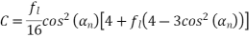
1. The device boundary criterion is the value of the mathematical expression:
RP – MP
where:
MP | : | is PL(lmn,Lmn) + LOP – Gr; |
RP | : | is the horizontally radiated power, measured in dBm EIRP per MHz, for each bearing, σn; |
Note: | | For a device with an active antenna system, the RP at bearing σn is defined as the sum of the gain of the antenna towards the horizontal plane and towards azimuth σn (dB) and the total radiated power (dBm). This allowance is based on the assumption that beam pointing angles and/or power can be controlled dynamically to ensure RP is not exceeded. |
LOP | : | is the level of protection. For radiocommunications transmitters that incorporate active antenna system (AAS), the LOP is -102 dBm per MHz. For radiocommunications transmitters without AAS, the LOP is –110 dBm per MHz; |
Gr | : | is the nominal radiocommunications receiver antenna gain including feeder loss set to 0 dBi; |
PL(lmn,Lmn) | : | is the propagation loss (dB) (calculated under Part 3 of this Schedule) of the mth increment on the nth radial. |
Part 3 Calculation of propagation loss
1. Subject to this Part 3, the propagation loss (or PL(lmn,Lmn)), for a radiocommunications transmitter, of the mth increment on the nth radial is calculated using:
(a) for a transmitter connected to an antenna which is located greater than 6 metres above ground level – the method and parameters defined in section 2.2 of Recommendation ITU-R P.525-4 and in section 4.5.2 of Recommendation ITU-R P.526-15;
(b) for a transmitter connected to an antenna which is located at or below 6 metres above ground level – the method and parameters defined in section 2.2 of Recommendation ITU-R P.525-4, in section 4.5.2 of Recommendation ITU-R P.526-15 and in section 3.2 of Recommendation ITU-R P.2108-0.
2. In implementing the method in section 4.5.2 of Recommendation ITU-R P.526-15:
(a) the height of the nominal receiver is 5 metres above ground level;
(b) the height of the transmitter above ground level is determined in accordance with Part 1 of Schedule 3 to this instrument; and
(c) the height of a profile point is determined in accordance with Part 2 of Schedule 3 to this instrument.
3. In implementing the method in section 4.5.2 of Recommendation ITU-R P.526-15:
(a) the path profile is developed by sampling the DEM-3S at 100 metre increments along each radial; and
(b) at each increment along the path profile, the procedure for calculating the average ground height described in Part 2 of Schedule 3 to this instrument is used.
4. In implementing the method in section 3.2 of Recommendation ITU-R P.2108-0:
(a) the percentage of locations is set at 0.0001% and the correction is applied at only one end of the path;
(b) if the loss calculated using the method in section 3.2 of Recommendation ITU-R P.2108-0 is less than 0 dB, the calculated loss value is replaced with 0 dB.
(section 10, items 2 and 3 of Part 3 of Schedule 2)
Part 1 Antenna height of a transmitter
1. The antenna height of a fixed transmitter is the vertical height in metres of the phase centre of the transmitters’s antenna, measured with an error of less than 5 parts in 100 and relative to the point:
(a) located on the line of intersection between the external surface of the structure supporting the antenna and the surface of the ground or sea; and
(b) having the lowest elevation on that line.
2. For a group of radiocommunications transmitters, the antenna height for the group is the greatest of the heights of each individual transmitter in the group, calculated in accordance with this Part.
Part 2 Average ground height
1. The average ground height at the mth increment on the nth radial is calculated as follows:
Step 1: Determine the associated latitude and longitude of the mth increment on the nth radial, (lmn, Lmn), as calculated in Part 3 of this Schedule.
Step 2: Identify the DEM-3S cell represented by (lmn, Lmn).
Note: See item 2 below for identifying the DEM-3S cell in a particular case.
Step 3: Bound the identified DEM-3S cell with the 8 adjacent DEM-3S cells in a 3 x 3 matrix and obtain each DEM-3S cell height attribute (as shown in Diagram 1).
Step 4: Determine the average value of the 9 DEM-3S cell heights for each cell in the the 3 x 3 matrix.
Diagram 1 Calculating average ground height
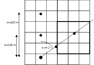
2. If (lmn, Lmn) has a modulus of zero when divided by 0.000833333, then the corresponding DEM-3S cell, for the purposes Step 2 in item 1, is the adjacent DEM-3S cell with the minimum height.
Note: Additional information for the case where (lmn, Lmn) corresponds to a DEM-3S cell boundary is provided in the document titled ‘Digital Elevation Model Interpretation’, available for free on the ACMA website: www.acma.gov.au.
Part 3 Vincenty’s Direct Formulae
Note: This implementation of Vincenty’s Direct Formulae uses the parameters  from the GRS80 ellipsoid as referenced by GDA94.
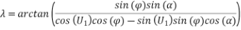
1. In calculating (lmn, Lmn):
lt | | is the latitude of the fixed transmitter (decimal radians) |
Lt | | is the longitude of the fixed transmitter (decimal radians) |
α | | is the azimuth angle (decimal radians) |
d | | is the separation distance to required point (m×100 metres) |
a | | is the semi-major axis with value 6378137 metres |
fl | | is the flattening of the value 1/298.25722210 |
b | | is the semi-minor axis of (a×(1-fl)) |


2. Using an initial value  , iterate the following three equations until the change in
  is less than 10-12.

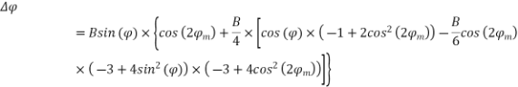
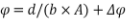
3. Then:

Note: Use the four-quadrant inverse tangent, atan2.
Note: Use the four-quadrant inverse tangent, atan2.