
Renewable Energy (Method for Solar Water Heaters) Determination 2016
made under regulation 19B of the
Renewable Energy (Electricity) Regulations 2001
Compilation No. 1
Compilation date: 15 March 2017
Includes amendments up to: Renewable Energy (Electricity) (Method for Solar Water Heaters) Amendment (Correction of Minor Errors) Determination 2017 (F2017L00208)
Prepared by the Clean Energy Regulator, Canberra
About this compilation
This compilation
This is a compilation of the Renewable Energy (Method for Solar Water Heaters) Determination 2016 that shows the text of the law as amended and in force on 15 March 2017 (the compilation date).
The notes at the end of this compilation (the endnotes) include information about amending laws and the amendment history of provisions of the compiled law.
Uncommenced amendments
There are no uncommenced amendments. All amendments are shown in the text of the compiled law.
Application, saving and transitional provisions for provisions and amendments
If the operation of a provision or amendment of the compiled law is affected by an application, saving or transitional provision that is not included in this compilation, details are included in the endnotes.
Editorial changes
For more information about any editorial changes made in this compilation, see the endnotes.
Modifications
If the compiled law is modified by another law, the compiled law operates as modified but the modification does not amend the text of the law. Accordingly, this compilation does not show the text of the compiled law as modified. For more information on any modifications, see the series page on the Legislation Register for the compiled law.
Self‑repealing provisions
If a provision of the compiled law has been repealed in accordance with a provision of the law, details are included in the endnotes.
Contents
1 Name
2 Commencement
3 Authority
4 Revocation
5 Definitions
6 Method to determine number of STCs
7 References to other documents
Schedule 1 – Methods
Part 1 – Method for solar waters heaters with a volumetric capacity up to and including 700 litres
Division A – Introduction
Division B – Method
Division C – Special Circumstances
Part 2 – Method for solar water heaters with a volumetric capacity more than 700 litres
Division A – Introduction
Division B – Method
Division C - Special Circumstances
Part 3 – TRNSYS Modelling Guidelines
Division A – Introduction
Division B – TRNSYS Decks
Division C – Measurement or analysis for TRNSYS modelling parameters
Division D - Notes
Endnotes
Endnote 1—About the endnotes
Endnote 2—Abbreviation key
Endnote 3—Legislation history
Endnote 4—Amendment history
This is the Renewable Energy (Method for Solar Water Heaters) Determination 2016.
(1) Each provision of this determination specified in column 1 of the table commences, or is taken to have commenced, in accordance with column 2 of the table. Any other statement in column 2 has effect according to its terms.
Commencement information |
Column 1 | Column 2 | Column 3 |
Provisions | Commencement | Date/Details |
1. The whole of this determination | 20 February 2017 | |
Note: This table relates only to the provisions of this determination as originally made. It will not be amended to deal with any later amendments of this determination.
(2) Any information in column 3 of the table is not part of this determination. Information may be inserted in this column, or information in it may be edited, in any published version of this determination.
This determination is made under subregulation 19B(1) of the Renewable Energy (Electricity) Regulations 2001.
All previous determinations made for the purposes of subregulation 19B(1) of the Renewable Energy (Electricity) Regulations 2001 are revoked.
In this determination:
AS 3498-2009 means Australian Standard AS 3498-2009 ‘Authorization requirements for plumbing products—Water heaters and hot-water storage tanks’.
AS 4552-2005 means Australian AS 4552-2005 ‘Gas fired water heaters for hot water supply and/or central heating’ as in force immediately before it was superseded by AS/NZS 5263.1.2:2016.
AS/NZS 2535.1:2007 means Australian/New Zealand Standard AS/NZS 2535.1:2007 ‘Test methods for solar collectors — Part 1: Thermal performance of glazed liquid heating collectors including pressure drop’.
AS/NZS 2712:2007 means Australian/New Zealand Standard AS/NZS 2712:2007 ‘Solar and heat pump water heaters – Design and construction’.
AS/NZS 4234:2008 means Australian/New Zealand Standard AS/NZS 4234:2008 ‘Heated water systems – Calculation of energy consumption’ as in force at the time it was made.
AS/NZS 4234:2008 Amendment 1 means Amendment No. 1 to the Australian/New Zealand Standard AS/NZS 4234:2008 ‘Heated water systems – Calculation of energy consumption’ made in March 2011.
AS/NZS 4234:2008 Amendment 2 means Amendment No. 2 to the Australian and New Zealand Standard AS/NZS 4234:2008 ‘Heated water systems – Calculation of energy consumption’ made in November 2011.
AS/NZS 5125.1:2010 means Australian/New Zealand Standard AS/NZS 5125.1:2010 ‘Heat pump water heaters – Performance assessment – Part 1: Air source heat pump water heaters’ as in force immediately before it was superseded by AS/NZS 5125.1:2014.
ASHP means a solar water heater that is an air source heat pump water heater.
COP means coefficient of performance.
extension package TRNAUS means the TRNSYS Extensions for Solar Water Heating prepared in February 2014 by Graham L. Morrison, School of Mechanical Engineering, University of New South Wales.
Note: The package could in December 2016 be viewed on Thermal Design Pty Ltd’s website (http://users.tpg.com.au/t_design).
interpolation means the mathematical method of estimating a value between values already known or determined.
large SWH means a solar water heater with a volumetric capacity over 700 litres, which is not an ASHP.
PV means photovoltaic.
small SWH (short for small solar water heater) means a solar water heater with a volumetric capacity up to and including 700 litres, which is not an ASHP.
STC means small-scale technology certificate.
SWH means solar water heater.
TRNSYS computer modelling package means versions 15 and 16 of the Transient Systems Simulation Program software package produced by the University of Wisconsin-Madison (Klein, S.A. et al, TRNSYS 16: A Transient System Simulation Program, Solar Energy Laboratory, University of Wisconsin, Madison, USA and Klein, S.A. et al, TRNSYS 15: A Transient System Simulation Program, Solar Energy Laboratory, University of Wisconsin, Madison, USA).
Note: Information about the package, including its distributors, could in December 2016 be viewed on the University of Wisconsin-Madison’s website (http://sel.me.wisc.edu/trnsys/index.html).
volumetric capacity means the total volume of water in litres that can be held in the storage tank, as defined in clause 1.5.24 of AS/NZS 2712:2007.
(1) For a model of SWH that is a small SWH or ASHP, the method to be used to determine the number of certificates that may be created for the model is set out in Part 1 of Schedule 1 to this Determination.
Note: Certificates cannot be created for a SWH that is an ASHP if it has a volumetric capacity of more than 425 litres – see subsection 21(4) of the Renewable Energy (Electricity) Act 2000.
(2) For a model of SWH that is a large SWH, the method to be used to determine the number of certificates that may be created for the model is set out in Part 2 of Schedule 1 to this Determination.
(3) The methods are to be used in accordance with the TRNSYS Modelling Guidelines set out in Part 3 of Schedule 1 to this Determination.
For the avoidance of doubt, unless the contrary intention appears, any reference to a document or any other writing is a reference to that document or other writing as in force at the time this determination is made.
This Part sets out the method for determining the number of STCs that may be created for models of SWHs that are small SWHs and ASHPs.
The method for determining the number of STCs that may be created for a small SWH or ASHP is based on AS/NZS 4234:2008 and AS/NZS 4234:2008 Amendments 1 and 2 with additional requirements specified in this Part.
Note: Guidance on whether an SWH that is a combined solar and heat pump water heater is to be considered an ASHP or a small SWH could in December 2016 be viewed on the Clean Energy Regulator’s website (http://www.cleanenergyregulator.gov.au/RET/Pages/Forms and resources/Forms-and-resources-for-manufacturers.aspx).
Small SWHs shall be rated for climate zones 1 to 4 specified in AS/NZS 4234:2008. ASHPs shall be rated for climate zones 1 to 5 based on the five heat pump climate zones HP1-Au to HP5-Au specified in AS/NZS 4234:2008 and AS/NZS 4234:2008 Amendments 1 and 2.
The method is as follows:
- Using the TRNSYS computer modelling package, format the TRNSYS deck files as set out in the TRNSYS Modelling Guidelines in Part 3 of this Schedule.
- Calculate the total annual auxiliary energy use (MWh/y) for the small SWH or ASHP using the TRNSYS computer modelling package with the following TRNSYS input parameters:
- Solar collector slope = 20°.
- Solar collector azimuth = 45°.
- For the climatic zones, use the weather data published by the Clean Energy Regulator.
Note: Weather data could in December 2016 be found on the Clean Energy Regulator’s website (http://www.cleanenergyregulator.gov.au/RET/Pages/Forms and resources/Forms-and-resources-for-manufacturers.aspx).
d. Select the appropriate hot water load for the small SWH or ASHP as detailed below. A minimum delivery temperature of 45°C must be achieved in each zone for which STCs are to be claimed.
- Select the hot water load (small, medium or large) for a small SWH. A minimum energy savings of 60% must be achieved in zone 3 for the small SWH to be rated with medium or large load.
- Select the hot water load (small or medium) for an ASHP. A minimum energy saving of 60% must be achieved in zone 3 for the ASHP to be rated as medium load.
- The percent energy savings, for the purpose of defining load size, shall be calculated as per clause 3.14.1 of AS/NZS 4234:2008.
- The modelling of the small SWH or ASHP shall show compliance with the legionella control requirements specified in AS 3498-2009.
- To rate thermosiphon SWHs and thermosiphon sidearm heat exchangers, use extension package TRNAUS.
- ASHP COP and power consumption performance shall be determined from full system tests in a temperature and humidity control test chamber to the requirements of AS/NZS 5125.1:2010 including the Low Temperature Performance Penalty for Class A Low Temperature products. The performance shall be correlated using the method described in AS/NZS 5125.1: 2010. All ASHPs that operate in heat pump mode at ambient temperatures lower than the initial frosting temperature shall include the Low Temperature Operation Penalty specified in AS/NZS 5125.1:2010 and AS/NZS 4234:2008 Amendment 1.
- The modelled lengths of piping shall be based on the following:
- For a pumped circulation system, the length of pipe between the storage tank and the closest corner of the solar collector array shall be the manufacturer’s specification or 10 m (each way), whichever is the larger.
- For a pumped circulation solar preheat tank, the length of piping between the pre-heat tank and a separate series auxiliary booster shall be the manufacturer’s specification or 5 m, whichever is the larger. If the auxiliary booster is integral with the pre-heat tank, then the actual pipe lengths shall be used.
- For a thermosiphon solar preheater, the length of piping between the preheat tank and a separate series auxiliary booster shall be the manufacturer’s specification or 10 m, whichever is the larger. If the auxiliary booster is integral with the preheat tank, then the actual pipe lengths shall be used.
- The diameter of all connecting piping shall be equal to the manufacturer’s specifications.
- If manufacturer’s specifications for the thermal conductivity of the pipe insulation are provided for the small SWH or ASHP, then those specified values are to be used. If no such specifications are provided, then the default values of 0.06 W/(m K) shall be used for closed cell foam insulation and 0.1 W/(m K) for rubberised insulation or polytube or fibre insulation.
- All other input parameters and control strategies must be those used in the actual small SWH or ASHP.
- Input parameters and control strategies are subject to modification by Division C of this Part.
3. For:
- Small SWHs (other than gas boosted SWHs) and ASHPs, subtract the total annual auxiliary energy use for the small SWH or ASHP, calculated in step 2, from the energy use of the reference electric water heater in AS/NZS 4234:2008 supplying the same load (Table A10 AS/NZS 4234:2008) to determine the displaced energy.
- Gas boosted SWHs, use Appendix G of AS/NZS 4234:2008 Amendment 1 to determine the displaced energy.
- Convert the displaced energy to MWh/y.
- Multiply the displaced energy in MWh/y by 10 to determine the 10 year MWh savings.
- Round down ten year MWh savings to the nearest lower integer.
- That number is the number of STCs that may be created for the small SWH or ASHP in the relevant zone.
The input parameters and control strategies used to calculate the total annual auxiliary energy for step 2 in the method in Division B of this Part are subject to modification in the following circumstances.
- Tanks with bottom element or capable of having a bottom element fitted
For systems where a bottom element is, or can be, fitted in the tank (e.g. a dual element tank), the bottom element is to be used in this method. The minimum boost time for a bottom element shall be nominal off-peak times of 11 pm to 6 am.
Some tank designs may be modified by the installer to insert an element at the bottom of the tank even if this element has been blanked off. If a small SWH or ASHP uses a tank that can have the bottom element connected at the time of installation or at any later time, the bottom element is to be used for rating purposes.
2. One-shot boosting
One-shot boosting is a manual control that allows a default boost mode (such as off-peak boosting) to be overridden so that the user can satisfy a short term high demand for hot water.
Where the system automatically resets to the default boosting mode within 24 hours of the user changing the boost mode, the one-shot boosting can be ignored.
Where the system does not automatically reset to the default boosting mode within 24 hours of the user changing the boost mode, the boosting mode activated by the manual control must be taken to be active at all times.
3. SWHs with hybrid photovoltaic/thermal solar collectors
For a small SWH or ASHP that utilises one or more photovoltaic/thermal (PV/T) hybrid solar collectors, which generate both electricity and useable thermal energy from the same collector, the following testing regime must be documented.
(a) PV output
The PV output shall be assessed using a collector with the water heating part of the collector empty.
(b) Water heating output
The thermal efficiency of the collector shall be assessed in accordance with AS/NZS 2535:2007 with the PV output set to maximum power conditions. The electrical output of the collector shall not be included in the thermal efficiency assessment.
Note: A small SWH or ASHP with PV/T collectors will only be eligible for STCs as a SWH in relation to the water heating component of the system.
This Part sets out the method for determining the number of STCs that may be created for models of SWHs that are large SWHs.
The method for determining the number of STCs that may be created for a large SWH is based on AS/NZS 4234:2008 and AS/NZS 4234:2008 Amendments 1 and 2, with additional requirements specified in this Determination.
Large SWHs shall be rated for climate zones 1 to 4 specified in AS/NZS 4234:2008.
The method is as follows:
- Using the TRNSYS computer modelling package, format the TRNSYS deck files as set out in the TRNSYS Modelling Guidelines in Part 3 of this Schedule.
- Calculate the total annual auxiliary energy use (MWh) for the large SWH using the TRNSYS computer modelling package, using the following TRNSYS input parameters:
- Solar collector slope = 20°.
- Solar collector azimuth = 45°.
- For the climatic zones, use the weather data published by the Clean Energy Regulator.
Note: Weather data could in December 2016 be found on the Clean Energy Regulator’s website (http://www.cleanenergyregulator.gov.au/RET/Pages/Forms and resources/Forms-and-resources-for-manufacturers.aspx).
d. The modelling of the product shall show compliance with the legionella control requirements specified in AS 3498-2009.
e. To rate thermosiphon SWHs and thermosiphon sidearm heat exchangers, use extension package TRNAUS.
f. Tank heat loss for a storage tank must be determined in accordance with the requirements met by the storage tank under regulation 3A(3)(c) of the Renewable Energy (Electricity) Regulations 2001, as in force from time to time.
g. The modelled lengths of piping shall be based on the following:
- For a pumped circulation system, the length of pipe between the storage tank and the closest corner of the solar collector array for shall be the manufacturer’s specification or 25 m (each way), whichever is the larger.
- For all systems the lengths of the supply and return pipes shall account for additional piping length associated with reverse return plumbing.
- For a pumped circulation solar preheat tank, the length of piping between the pre-heat tank and the series auxiliary booster shall be the manufacturer’s specification or 10 m, whichever is the larger. If the auxiliary booster is integral with the pre-heat tank, then the actual pipe lengths shall be used.
- For a thermosiphon solar preheater, the length of piping between the preheater and the series auxiliary booster shall be the manufacturer’s specification or 25 m, whichever is the larger. If the auxiliary booster is integral with the pre-heat tank, then the actual pipe lengths shall be used.
- For systems with solar preheat and finishing tank, where the finishing tank is heated by a recirculating instantaneous auxiliary booster, the length of piping between finishing tank and booster shall be the manufacturer’s specification or 2 m (each way), whichever is the larger.
- The diameter of all connecting piping shall be equal to the manufacturer’s specifications.
- If manufacturer’s specifications for the thermal conductivity of the pipe insulation are provided for the large SWH, then those specified values are to be used. If no such specifications are provided, then the default values of 0.06 W/ (m K) shall be used for closed cell foam insulation and 0.1 W/(m K) for rubberized insulation or polytube or fibre insulation.
- All other input parameters and control strategies must be those used in the actual large SWH.
- Input parameters and control strategies are subject to modification by Division C of this Part.
- Select the peak daily winter load in accordance with the scale of the installation. The load shall be the same for all zones and set such that the large SWH achieves at least 60% annual energy savings in zone 3. A minimum delivery temperature of 45°C must be achieved for each zone in relation to which STCs are to be created. The individual hot water load draw-offs shall be applied over a period of 1 h.
- The percent energy savings,
- for the purpose of defining the peak daily winter load of electrically boosted systems, shall be calculated as per clause 3.14.1 of AS/NZS 4234:2008 (as in force at the commencement of the Renewable Energy (Electricity) (Method for Solar Water Heaters) Amendment (Correction of Minor Errors) Determination 2017), except the annual reference energy use shall be as calculated in Step 5.c., and
- for the purpose of defining the peak daily winter load of gas boosted systems, shall be calculated as per clause 3.14.1 of AS/NZS 4234:2008 (as in force at the commencement of the Renewable Energy (Electricity) (Method for Solar Water Heaters) Amendment (Correction of Minor Errors) Determination 2017), except the annual energy use shall be as calculated in Step 5.d.
- Determine the annual energy use of an electric reference water heater (‘the reference system’) supplying the same hot water load, as follows:
- The heat loss from the reference system shall be 15% of the hot water load, therefore use a factor of 1.15.
- The time weighted average seasonal load multiplier to be used is 0.905 (see AS/NZS 4234:2008).
- For electrically boosted systems multiply number of days in a year (365) by time weighted average seasonal load multiplier (0.905), by heat loss factor percentage (1.15) by the peak daily winter load.
- For gas boosted systems multiply number of days in a year (365) by time weighted average seasonal load multiplier (0.905), by heat loss factor percentage (1.15) by the peak daily winter load and divide by the reference gas water heater thermal efficiency (0.788) as stated in Table A9 of AS/NZS 4234:2008.
- Determine the displaced energy as follows:
- For electrically boosted systems subtract the total annual auxiliary energy use for the large SWH, calculated in Step 2, from the annual energy use, calculated in Step 5.c., to determine the displaced energy.
- For gas boosted systems, the displaced energy is the equivalent displaced electric energy. The equivalent displaced electric energy shall be determined using Appendix G of AS/NZS 4234:2008 and the annual electrical energy use of the reference electric heater shall be as calculated in Step 5.c.
- Convert the displaced energy to MWh/y.
- Multiply the displaced energy (MWh/y) by 10 to determine the 10 year MWh savings.
- Round down the ten year MWh savings to the nearest lower integer.
- That number is the number of STCs that may be created for the large SWH in the relevant zone.
The input parameters and control strategies used to calculate the total annual auxiliary energy for step 2 in the method in Division B of this Part are subject to modification in the following circumstances.
- Tanks with bottom element fitted
For systems where a bottom element is fitted in the tank (e.g. a dual element tank) the bottom element is to be used for rating purposes. The minimum boost time for a bottom element shall be nominal off-peak times of 11 pm to 6 am.
2. One-shot boosting
One-shot boosting is a manual control that allows a default boost mode (such as off-peak boosting) to be overridden so that the user can satisfy a short term high demand for hot water.
Where the system automatically resets to the default boosting mode within 24 hours of the user changing the boost mode, the one-shot boosting can be ignored.
Where the system does not automatically reset to the default boosting mode within 24 hours of the user changing the boost mode, the boosting mode activated by the manual control must be considered to be active at all times
3. SWHs with hybrid photovoltaic/thermal solar collectors
For a large SWH that utilises photovoltaic/thermal (PV/T) hybrid solar collectors, which generate both electricity and useable thermal energy from the same collector, the following testing regime must be documented.
(a) PV output
The PV output shall be assessed using a collector with the water heating part of the collector empty.
(b) Water heating output
The thermal efficiency of the collector shall be assessed in accordance with AS/NZS 2535:2007 with the PV output set to maximum power conditions. The electrical output of the collector shall not be included in the thermal efficiency assessment.
Note: A large SWH with PV/T collectors will only be eligible for STCs as a SWH in relation to the water heating component of the system.
4. Family of products
A ‘family of products’ means a combination of tanks, collectors, boosters and pumps that are used in a modular fashion to create a product range of different sizes. An interpolation or a sub-unit approach may be used for the performance rating of a family of products as detailed in the below two paragraphs.
a) Interpolation approach: interpolation of performance for a scaled family of products
An interpolation approach may be used if all members of a family of products must have the:
- same solar collector;
- same ratio of collector area to tank volume; and
- same collector flow rate per unit area.
The performance of the family of products may be determined from detailed simulation of the performance of the largest, smallest and midpoint system sizes with the pipes, boosters and pumps they include. The performance of other members of the family may be determined by interpolation using a non-linear fit to the ratings of the largest, smallest and midpoint products. Auxiliary boosters and pumps for each interpolated model must have equal or greater efficiency than the smallest member of the interpolated range.
b) Sub-unit approach: parallel sub-unit family of products
A sub-unit approach may be used if a family of products consists of parallel sub-units that each have an identical solar collector array, storage tank, booster and pump configuration.
The system performance rating of the family of products may be determined by multiplying the STC of one sub-unit by the number of sub-units and rounding down the resulting STC. The volume of each sub-unit tank may be less than 700 litres, but the combined physical inner tank volume of each member of the family of products must be greater than 700 litres.
The following system configuration variations in the installed systems may be used:
- the collector arrays of the multiple sub-units may be combined into one inter-connected collector array;
- the multiple sub-unit pumps may be replaced with one or more larger pumps of lower overall power consumption;
- the multiple sub-unit piping may be replaced with larger diameter piping provided the pipe insulation thermal resistance is equal to or larger than the pipe insulation resistance in the rated sub-unit; and
- the collector flow rate per unit area in a composite system shall be the same as for the rated sub-unit. This also applies to composite systems in which the pump and/or piping has been modified from the rated sub-unit.
This Part sets out the TRNSYS Modelling Guidelines, which must be adhered to in using the methods in Parts 1 and 2 of this Schedule. The TRNSYS Modelling Guidelines specify the format and structure required for the TRNSYS deck files, and the default values to be used in certain circumstances.
Deck layout
- All include files shall be at the top of the deck immediately after the SIMULATION statement and the timestep shall be 0.02 h or less
- The chosen time step shall be an exact divisor of the load draw off period.
- The TOLERANCE statement shall be 0.005, 0.005 or less for relative tolerances.
- Each load draw-off event shall be applied over a period of 0.1 h for small SWHs and ASHPs and 1 h for large SWHs.
- Use the template deck structure in the version of the document titled CER template decks published by the Clean Energy Regulator, unless the Clean Energy Regulator approves in writing. Except for the product parameters, the template decks shall be used without modification unless the product has features not covered by the example decks. There are different template decks for small SWHs, ASHPs and large SWHs.
Note: The document ‘CER template decks’ could in December 2016 be viewed on the Clean Energy Regulator’s website (http://www.cleanenergyregulator.gov.au/RET/Pages/Forms and resources/Forms-and-resources-for-manufacturers.aspx).
- The include files provided by the Clean Energy Regulator shall not be modified.
- All constants shall be towards the top of the deck.
- The output, list and other output file names shall be the same as the deck name except for the file type.
- The output printers in the example decks shall not be modified. Additional printers may be used if required.
Simulation display
- Simulation output: A TYPE 25 printer unit shall be included in the deck. This shall output the following results: the zone, load size, percent energy savings, STC rating and annual energy delivered below 45°C.
- Energy balance: A monthly energy balance in a TYPE 28 output unit shall be included in the deck. This shall include a full system energy balance i.e. collector input + boosting + pump input – load – pipe losses – tank losses – energy dumped.
- Runtime graph: A runtime graph (TYPE65) shall be included in each deck showing at least:
- Hot water delivery temperature
- Solar collector flow rate
- Solar collector inlet temperature
- Solar collector outlet temperature
- Load
- Similar variables shall be plotted for heat pump water heaters.
Solar collector area
- The area specified for the solar collector (absorber, aperture or gross) shall be the same as the area used for the specification of the solar collector efficiency coefficients.
Controller default settings
- If the maximum tank temperature setting of the pump controller used for no-load system operation test (clause 7.4.3.2 in AS/NZS 2712:2007) is not specified in the AS/NZS 2712:2007 test report, then a maximum value of 65°C shall be used (Tmax = 65oC and Tmax_reset = 60oC shall be used in the modelling).
- For a simple temperature difference pump controller the minimum turn off temperature difference shall be 1 K.
Piping models
- All piping shall be modelled using the TYPE 31 pipe routine.
Instantaneous gas heater defaults
- If an instantaneous gas booster has not been assessed for electrical power consumption during standby under AS 4552-2005, then a value of 10 W shall be used. If the electrical power consumption during burner operation is not available, then a value of 50 W shall be used.
- If the startup heat loss has not been assessed under AS 4552-2005, then a default value of 0.5 MJ shall be used.
- AS 3498-2009 requires water heating to minimum of 70oC for a storage solar preheat system with an inline instantaneous gas booster when the solar preheat tank temperature is less than 55oC (clause 7 (j) (vi)). If a gas booster trigger temperature (≥ 55oC) less than the gas booster set point temperature (≥ 70oC) is used, then specifications for the gas booster control logic shall be provided. If specifications for the gas booster control logic are not provided, the trigger temperature used for rating purposes shall be equal to the gas booster set point temperature at all times.
Stratification option for pumped circulation tanks
- The default stratification specification for a pumped circulation storage tank shall be “Uncontrolled flow pumped circulation” (AS/NZS 4234:2008 clause 3.7.4 or H3.4). For pump circulation SWHs satisfying the "Low flow criteria" (AS/NZS 4234: 2008 clause 3.7.2 or H3.2) the tank thermal stratification shall be modelled as per AS/NZS 4234:2008 clause 3.8.2 or H4.2, if:
- for solar preheat tanks, the collector flow return to the tank is in the top 2/3 of the tank; or
- for in-tank electrically boosted solar tanks, the collector flow return to the tank is in the top 2/3 of the tank and the solar return is below any electric element; or
- for tanks connected to stand alone heat pumps, the heat pump flow return to the tank is in the top 2/3 of the tank.
- For booster tanks in large SWHs where the water temperature is boosted with a separate pumped recirculation loop “Uncontrolled flow pumped circulation” shall be assumed unless:
- the return from the recirculation booster loop to the tank is in the top 2/3 of the tank; and
- the recirculation flow rate is below 1 L/min per kW thermal power added by the external booster; and
- the booster tank recirculation water turnover rate is less than 1 tank volume per hour.
Effective air temperature
- The effective air temperature used to determine solar collector and piping heat loss during night time (horizontal irradiation < 1 kJ/h.m2) shall be Taeff = Ta – (Ta –Tsky)/5, where Ta denotes the ground level air temperature and Tsky the sky temperature as defined by AS/NZS 4234:2008.
- The effective air temperature used to determine solar collector and piping heat loss during day time (horizontal irradiation ≥ 1 kJ/h.m2) shall be Taeff = Ta.
Dip tubes
- Note for a tank with dip (or snorkel) tube, the heat transfer between the stored tank water and the water flowing inside the dip tube usually is small compared to the heat capacitance rate of the water flowing through the tube. In this case the temperature of the water supplied to the collector inlet pipe (or the load) shall be the tank temperature at the dip (or snorkel) tube inlet. Evidence of any dip (or snorkel) tubes must be included in tank drawings supplied for system audits.
Height parameters for thermosyphon SWHs
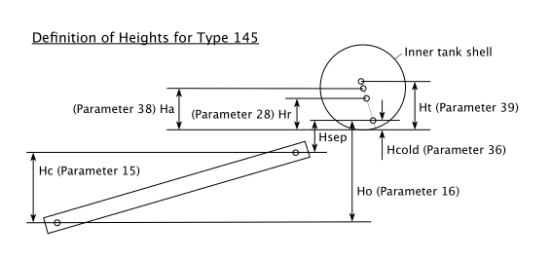
Note: If a dip tube is used on the cold inlet port then the measurements Hsep and Hcold are relative to the level of the outlet of the dip tube.
Units
- The units system used in TRNSYS is metre, kg, h and kJ. All energy transfer rate parameters must be converted from W to kJ/h (multiply Watts by 3.6 to get kJ/h).
Rounding of numerical results
- The printing of STC and Energy Savings % outputs shall use the format F5.1 as specified in the example decks. This means that an STC rating of 20.94 will be rounded down to 20.9 in the printout and this will be taken as STC = 20. An STC rating of 20.96 will be rounded up to 21.0 in the print out and this will be taken as STC = 21.
Site specific pump flow rate setting
- Pumped circulation SWHs are classified as “controlled flow” or “uncontrolled flow” systems in clause 3.7.2 of AS/NZS4234:2008.
- If a pumped SWH is claimed to be a “controlled flow” system, then documentation demonstrating how the flow rate is controlled for every installation shall be provided. The alternative product configurations that shall be detailed in the installation manual are:
- Flow meter in every installation
If a flow meter is fitted in every installation with an adjusting valve that is not easily accessible by the user then provide a copy of the flow meter specification and the SWH installation manual detailing the flow setting procedure. The pump power use shall be measured as detailed below. - Flow meter used during commissioning
If a flow meter is fitted in every installation and the flow rate set by an adjusting valve that is not easily accessible by the user and the flow meter is removed after commissioning, then provide a copy of the flow meter specification and the SWH installation manual detailing the flow setting procedure. The pump power use shall be measured as detailed below. - Flow rate set by controller
If the pump flow rate is set by a controller based on a real time signal from a flow meter or the temperature rise in the collector circuit or by another real time signal, then provide a copy of the controller logical functions and provide measured flow rate and pump electrical power as detailed below. - Orifice restrictors
If a set of orifice restrictors are used to set the flow rate for installations with different collector loop piping lengths and number of collectors then provide a copy of the installation manual detailing how the appropriate orifice is selected on the basis of the site specific piping lengths and number of solar collectors. The pump flow rate and power use shall be measured as detailed below. - Other site specific flow control method
Provide details if applicable.
Measurement and documentation of pump flow rate and power
- For small SWHs the collector loop flow rate and pump electrical power input to be used in the method must be measured for a typical system installation as specified in Step 2.h. of the method in Division B of Part 1.
- For large SWHs the collector loop flow rate and pump electrical power input to be used in the method may be either measured or calculated for a typical system installation as specified in Step 2.g. of the method in Division B of Part 2. These measurements or calculations shall be carried out for the specific collector array size or recirculation loops that are specified for the product.
- Measurements or calculations for products with variable flow rate shall cover the full range of operating conditions.
- A report must be prepared setting out the measurement or calculation of pump flow rate and power. The report must include:
- a description of product configuration tested, including collector model, number of collectors, series or parallel connection, pump model, piping length and diameter; and
- a detailed description of the measurement or calculation procedure used, including schematic diagram or photograph of setup; and
- (if measured rather than calculated) measuring equipment used; and
- (if measured rather than calculated) results for flow rate and pump electrical power input.
- The Clean Energy Regulator has published a procedure that may be used to calculate pump flow rate and power consumption for large SWHs, titled Guide for Calculating Pump Flow Rate and Power Consumption for Large Solar Water Heaters. For the avoidance of doubt, use of the procedure is not mandatory.
Note: The guide could in December 2016 be viewed on the Clean Energy Regulator’s website (http://www.cleanenergyregulator.gov.au/RET/Pages/Forms and resources/Forms-and-resources-for-manufacturers.aspx).
Pump cycling and simulation stability
- For pumped SWHs the pump controller may cycle the pump on/off if the ratio Ton/Toff is too small. See Duffie & Beckman, "Solar Engineering of Thermal Processes", Section 10.4 Controls for more detail [1] and how to calculate the required Ton/Toff ratio to avoid pump cycling.
- Modelling an in-tank coil heat exchanger for the solar circulation loop using the Type 60 tank model can lead to convergence problems in TRNSYS 15, particularly for glycol-water mixtures. Using water as the HX fluid instead and/or artificially increasing the collector flow rate may overcome this problem. Changing the heat transfer fluid and/or flow rate will introduce an error, and the increase in flow rate should be kept as small as possible.
Batching multiple TRNSYS rating Calculations
- Running multiple TRNSYS decks can be automated by using a Windows batch file. For example, four decks (deckfilenameZ1 to deckfilenameZ4) can be run successively by writing the following lines into a Notepad file (note the spaces) and saving the file with .bat extension.
C:\Trnsys15\trnsys.exe deckfilenameZ1.dck /N
C:\Trnsys15\trnsys.exe deckfilenameZ2.dck /N
C:\Trnsys15\trnsys.exe deckfilenameZ3.dck /N
C:\Trnsys15\trnsys.exe deckfilenameZ4.dck /N
Right-clicking the batch file allows to one to edit it, left clicking or double clicking will run it.
References
[1] Duffie, J. A. and Beckman, W. A., Solar Engineering of thermal processes, 3rd ed., Wiley, New York, 2006.
The endnotes provide information about this compilation and the compiled law.
The following endnotes are included in every compilation:
Endnote 1—About the endnotes
Endnote 2—Abbreviation key
Endnote 3—Legislation history
Endnote 4—Amendment history
Abbreviation key—Endnote 2
The abbreviation key sets out abbreviations that may be used in the endnotes.
Legislation history and amendment history—Endnotes 3 and 4
Amending laws are annotated in the legislation history and amendment history.
The legislation history in Endnote 3 provides information about each law that has amended (or will amend) the compiled law. The information includes commencement details for amending laws and details of any application, saving or transitional provisions that are not included in this compilation.
The amendment history in Endnote 4 provides information about amendments at the provision (generally section or equivalent) level. It also includes information about any provision of the compiled law that has been repealed in accordance with a provision of the law.
Misdescribed amendments
A misdescribed amendment is an amendment that does not accurately describe the amendment to be made. If, despite the misdescription, the amendment can be given effect as intended, the amendment is incorporated into the compiled law and the abbreviation “(md)” added to the details of the amendment included in the amendment history.
If a misdescribed amendment cannot be given effect as intended, the abbreviation “(md not incorp)” is added to the details of the amendment included in the amendment history.
| o = order(s) |
ad = added or inserted | Ord = Ordinance |
am = amended | orig = original |
amdt = amendment | par = paragraph(s)/subparagraph(s) |
c = clause(s) | /sub‑subparagraph(s) |
C[x] = Compilation No. x | pres = present |
Ch = Chapter(s) | prev = previous |
def = definition(s) | (prev…) = previously |
Dict = Dictionary | Pt = Part(s) |
disallowed = disallowed by Parliament | r = regulation(s)/rule(s) |
Div = Division(s) | |
exp = expires/expired or ceases/ceased to have | reloc = relocated |
effect | renum = renumbered |
F = Federal Register of Legislation | rep = repealed |
gaz = gazette | rs = repealed and substituted |
LA = Legislation Act 2003 | s = section(s)/subsection(s) |
LIA = Legislative Instruments Act 2003 | Sch = Schedule(s) |
(md) = misdescribed amendment can be given | Sdiv = Subdivision(s) |
effect | SLI = Select Legislative Instrument |
(md not incorp) = misdescribed amendment | SR = Statutory Rules |
cannot be given effect | Sub‑Ch = Sub‑Chapter(s) |
mod = modified/modification | SubPt = Subpart(s) |
No. = Number(s) | underlining = whole or part not |
| commenced or to be commenced |
Name | Registration | Commencement | Application, saving and transitional provisions |
Renewable Energy (Method for Solar Water Heaters) Determination 2016 | 6 Jan 2017
(F2017L00028) | 20 Feb 2017 (s 2) | — |
Renewable Energy (Electricity) (Method for Solar Water Heaters) Amendment (Correction of Minor Errors) Determination 2017 | 14 Mar 2017
(F2017L00208) | 15 Mar 2017 (s 2) | — |
Provision affected | How affected |
s 1……………………..….. | am. No F2017L00208 |
| |
Schedule 1 | |
| |
Division B of Part 1 | |
Step 2.h.iii. of the method.. | rep. No F2017L00208 |
Steps 2.h.iv to vi. of the method………………….... |
renum. No F2017L00208
|
| |
Division B of Part 2 | |
Step 4 of the method…..…. | rs. No F2017L00208 |
Step 6.a. of the method..…. | am. No F2017L00208 |
Step 6.b. of the method..…. | am. No F2017L00208 |
| |
Division C of Part 3 | |
(Measurement and documentation of pump flow rate and power) | |
First dot-point……..……... | am. No F2017L00208 |
Second dot-point….……... | am. No F2017L00208 |