
Carbon Credits (Carbon Farming Initiative) (Destruction of Methane Generated from Dairy Manure in Covered Anaerobic Ponds) Methodology Determination 2012
made under the
Carbon Credits (Carbon Farming Initiative) Act 2011
Compilation No. 1
Compilation date: 1 July 2015
Includes amendments up to: Carbon Credits (Carbon Farming Initiative—Emissions Reduction Fund) Methodology Determination Variation 2015
About this compilation
This compilation
This is a compilation of the Carbon Credits (Carbon Farming Initiative) (Destruction of Methane Generated from Dairy Manure in Covered Anaerobic Ponds) Methodology Determination 2012 that shows the text of the law as amended and in force on 1 July 2015 (the compilation date).
This compilation was prepared on 1 July 2015 by the Department of the Environment.
The notes at the end of this compilation (the endnotes) include information about amending laws and the amendment history of provisions of the compiled law.
Uncommenced amendments
The effect of uncommenced amendments is not shown in the text of the compiled law. Any uncommenced amendments affecting the law are accessible on ComLaw (www.comlaw.gov.au). The details of amendments made up to, but not commenced at, the compilation date are underlined in the endnotes. For more information on any uncommenced amendments, see the series page on ComLaw for the compiled law.
Application, saving and transitional provisions for provisions and amendments
If the operation of a provision or amendment of the compiled law is affected by an application, saving or transitional provision that is not included in this compilation, details are included in the endnotes.
Modifications
If the compiled law is modified by another law, the compiled law operates as modified but the modification does not amend the text of the law. Accordingly, this compilation does not show the text of the compiled law as modified. For more information on any modifications, see the series page on ComLaw for the compiled law.
Self‑repealing provisions
If a provision of the compiled law has been repealed in accordance with a provision of the law, details are included in the endnotes.
Contents
Part 1 Preliminary
1.1 Name of Determination
1.2 Commencement
1.2A Duration
1.3 Application
1.4 Definitions
Part 2 Requirements that must be met for declaration as an eligible offsets project
2.1 Requirements that must be met for an offsets project to be an eligible offsets project
Part 3 Calculating the carbon dioxide equivalent net abatement amount for an eligible offsets project for a reporting period
Division 3.1 Preliminary
3.1 General
3.2 Greenhouse gas assessment boundary
3.3 Calculating the baseline for the project
Division 3.2 Calculations
Subdivision 3.2.1 Calculating baseline emissions (Eb)
3.4 Calculating the baseline methane emissions
Subdivision 3.2.2 Calculating volatile solids (VS)
3.5 Calculating VS using the tier one method
3.6 Calculating VS using the tier two method
3.7 Calculating VS using the tier three method
Subdivision 3.2.3 Calculating the carbon dioxide equivalent net abatement amount
3.8 Calculating net greenhouse gas abatement (A)
3.9 Capping the volume of methane
3.10 Determining the methane destruction efficiency for a combustion device (DEh)
Subdivision 3.2.4 Calculating nitrous oxide emissions
3.11 Calculating nitrous oxide emissions (
Subdivision 3.2.5 Calculating emissions combusted in an internal combustion engine
3.12 Quantity of emissions combusted in an internal combustion engine – optional verification methods
Subdivision 3.2.6 Calculating emissions from fuel used to operate the gas extraction system in the project (Yp)
3.13 Calculating emissions from fuel use (Yp)
Division 3.3 Data Collection
3.14 Data collection procedures and measurement frequency
3.15 Measuring the quantity of biogas sent to combustion device h (Qbiogas,h)
3.16 Measuring the proportion of volume of biogas that is methane ( )
)
Part 4 Monitoring and Reporting
Division 4.1 Project monitoring
4.1 Application
4.2 Quality assurance and quality control
Division 4.2 Record-keeping requirements
4.3 Information for calculating the baseline
4.4 General information
4.5 Information about combustion devices
4.6 Information about monitoring devices
4.7 Information about gas composition
4.8 Information about direct and indirect measurement
Division 4.3 Offsets report requirements
4.9 Information required in offsets reports
Division 4.4 Reporting under section 77A of the Act
4.10 Division compatible with calculations
Endnotes
Endnote 1—About the endnotes
Endnote 2—Abbreviation key
Endnote 3—Legislation history
Endnote 4—Amendment history
Part 1 Preliminary
1.1 Name of Determination
This Methodology Determination is the Carbon Credits (Carbon Farming Initiative) (Destruction of Methane Generated from Dairy Manure in Covered Anaerobic Ponds) Methodology Determination 2012.
1.2 Commencement
This Methodology Determination is taken to commence on 1 July 2010.
1.2A Duration
This Determination remains in force for the period that:
(a) begins when the Determination commences; and
(b) ends on the day before this Determination would otherwise be repealed under subsection 50 (1) of the Legislative Instruments Act 2003.
1.3 Application
For paragraph 106 (1) (a) of the Act, this Methodology Determination applies to an agricultural emissions avoidance project that:
(a) proposes to capture biogas generated by the decomposition of dairy effluent in anaerobic ponds and to combust the methane component of the captured biogas; and
(b) could reasonably be expected to result in eligible carbon abatement.
1.4 Definitions
In this determination:
Act means the Carbon Credits (Carbon Farming Initiative) Act 2011 as in force from time to time.
active pond volume means the volume of an anaerobic pond consisting primarily of water, organic matter and live microorganisms and not the sludge storage volume which exists at the lowest level of the pond.
anaerobic decomposition means a biological process in which organic matter is broken down by bacteria in the absence of oxygen.
biogas means a mixture of gases that is generated as a result of anaerobic decomposition.
carbon dioxide equivalence (CO2-e) means the carbon dioxide emissions equivalence of a substance that produces greenhouse gas emissions.
combustion device means an open flare or a closed flare, an internal combustion engine or a gas boiler.
dairy farm means a farm that, for its primary purpose, engages in dairy cow farming, raw cow milk production or share milking.
DGAS Calculator means the version of the Dairy Greenhouse Gas Abatement Strategies Calculator, produced by staff from the University of Tasmania, University of Melbourne and government of Victoria, that is referred to from time to time on the Department’s website with a statement that:
(a) it is the DGAS Calculator for this Determination; and
(b) if the version differs from version 1.4—the differences consist only of one or more of the following:
(i) updates to inputs and variables used by the DGAS Calculator which are consistent with the National Inventory Report;
(ii) updates which are of a minor nature;
(iii) updates which are necessary or incidental to updates referred to in subparagraph (i) or (ii).
DGAS Manual means the user manual as in force from time to time that is associated with the version of the DGAS Calculator referred to from time to time on the Department’s website.
effluent means a mixture of water, excreta, liquid waste and slurry resulting from cleaning impervious surfaces around the dairy shed, feedpad or any cow housing. This includes, but is not limited to, chemicals and residual milk from cleaning equipment, waste feed and bedding, and runoff from such areas.
Effluent and Manure Management Database means the version of the Effluent and Manure Management Database for the Australian Dairy Industry published by Dairy Australia that is referred to from time to time on the Department’s website with a statement that:
(a) it is the Effluent and Manure Management Database for this Determination; and
(b) if the version differs from the version published by Dairy Australia in 2008—the differences consist only of one or more of the following:
(i) updates to inputs and variables used by the database which are consistent with the National Inventory Report;
(ii) updates which are of a minor nature;
(iii) updates which are necessary or incidental to updates referred to in subparagraph (i) or (ii).
enclosed flare means a device where residual gas is burned in a cylindrical or rectilinear enclosure that includes a burning system and a damper where air for the combustion reaction is admitted.
Faecal Methane Worksheet means the spreadsheet of that name located within the DGAS Calculator.
flaring system means the system used to combust biogas which includes an open flare or an enclosed flare.
frequently sparking flare means a flare that sparks at least every two seconds.
gas boiler means a combustion device for gaseous fuels, including biogas, that is used for heating water or raising steam.
GWPCH4 means the global warming potential of methane, as prescribed in the NGER Regulations.
herd recording event means the counting and recording of the number of milking cows in the herd.
internal combustion engine means an engine in which the combustion of a fuel occurs with an oxidizer in a combustion chamber.
monitoring instrument means an instrument for measuring a quantity.
NATA means the National Association of Testing Authorities, Australia (ACN 004 379 748).
National Inventory Report means the most recently published document that:
(a) is known as the National Inventory Report; and
(b) was prepared by the Department in fulfilment of obligations that Australia has under the Climate Change Convention.
National Measurement Act means the National Measurement Act 1960 as in force from time to time.
NGER (Measurement) Determination means the National Greenhouse and Energy Reporting (Measurement) Determination 2008 as in force from time to time.
NGER Regulations means the National Greenhouse and Energy Reporting Regulations 2008 as in force from time to time.
open flare means a device where residual gas is burned in open air with or without any auxiliary fuel assistance.
pond means a dam into which effluent is deposited, stored or treated.
standard conditions has the same meaning provided in the NGER (Measurement) Determination.
sludge storage volume means the volume of an anaerobic pond located at the bottom consisting primarily of material that cannot readily be anaerobically decomposed.
US EPA Method means, in relation to a test mentioned in this Methodology Determination, the test method approved by the United States Environmental Protection Agency by the same name, as amended from time to time.
Note A link to these methods is available at: http://www.climatechange.gov.au
volatile solids (VS) means that portion of the total solids driven off as volatile (combustible) gases when heated at 550 degrees Celsius (+/- 50 degrees) for at least one hour.
Part 2 Requirements that must be met for declaration as an eligible offsets project
2.1 Requirements that must be met for an offsets project to be an eligible offsets project
(1) For paragraph 106 (1) (b) of the Act, this section sets out the requirements that must be met for an offsets project to which this Methodology Determination applies to be an eligible offsets project.
(2) The project is an agricultural emissions avoidance project that:
(a) uses covered ponds to prevent the release of biogas;
(b) collects the biogas from the covered pond; and
(c) combusts the methane component in the biogas to convert it to carbon dioxide.
(3) The ponds referred to in paragraph (2) (a) must:
(a) have a minimum loading rate of 50g of volatile solids per cubic metre of active pond volume per day; and
(b) comply with the standards for the construction, operation and maintenance of ponds as prescribed in the Effluent and Manure Management Database.
(4) Only effluent from the management of dairy cows within the project may be deposited in the project ponds.
(5) Any flaring system used in the project must:
(a) use a frequently sparking flare to ensure continuous destruction of methane; or
(b) include a control system that prevents gas flow through the flare when the flare is not operational.
(6) Where paragraph (5) (b) applies:
(a) the flaring system must include a temperature monitoring system that ensures the flare is operating at the temperature required for complete combustion of methane; and
(b) when the flare temperature drops below the temperature required for complete combustion of methane, the control system must shut down biogas flow through the flare.
Part 3 Calculating the carbon dioxide equivalent net abatement amount for an eligible offsets project for a reporting period
Division 3.1 Preliminary
3.1 General
(1) For paragraph 106 (1) (c) of the Act, the carbon dioxide equivalent net abatement amount for an eligible offsets project is equal to the amount ascertained using the method set out in this Part.
(2) In this Part:
(a) all calculations are in respect of activities undertaken, or outcomes achieved, during the reporting period for the eligible offsets project;
(b) unless otherwise specified:
(i) a reference to a project is a reference to an eligible offsets project that meets the requirements of section 2.1;
(ii) all references to Parts, Divisions, sections, subsections, paragraphs and Equations are references to corresponding parts of this Methodology Determination.
(c) for all equations:
(i) n = number of combustion devices; and
(ii) h denotes a combustion device.
(3) References in Division 3.2 to a factor or parameter prescribed in the NGER (Measurement) Determination or the NGER Regulations, are, for the entire offsets reporting period, references to the NGER (Measurement) Determination or NGER Regulations in force at the end of the reporting period.
(4) The data used in the calculations set out below in Division 3.2 must comply with the data collection requirements set out in Division 3.3.
(5) The use of the DGAS Calculator and Effluent and Manure Management Database in the calculations under this Part must be in accordance with any guidelines relating to the use of that calculator and database for the purposes of this Determination published from time to time on the Department’s website.
3.2 Greenhouse gas assessment boundary
(1) The following greenhouse gases from the following sources within the project must be taken into account when making calculations under this Part. No other gases may be taken into account in respect of a source.
3.3 Calculating the baseline for the project
(1) The baseline for a project is the total amount of methane that would have been generated and released from all ponds used in the project, for each year of the project, in the absence of the abatement activity, including that the ponds were uncovered.
(2) The baseline must be calculated based on the amount of volatile solids in the effluent stream deposited into each pond used in the project, which is calculated in accordance with Division 3.2.
Division 3.2 Calculations
Subdivision 3.2.1 Calculating baseline emissions (Eb)
3.4 Calculating the baseline methane emissions
(1) The baseline for the project is calculated as follows:

| Equation 1.1 |
Where:
Eb = total methane emissions that would have occurred from the operation of all of the ponds used in the project, as if the project did not occur, including that the ponds were uncovered, in tonnes of CO2-e.
 = the factor 6.784 x 10⁻⁴ x
  converting cubic metres of methane to tonnes of CO2-e at standard conditions.
Qb = total volume of methane that would be released to the atmosphere from the operation of the ponds used in the project, as if the project did not occur, including that the ponds were uncovered, in cubic metres of methane (m3 CH4) at standard conditions.
(2) Qb must be calculated as follows:

| Equation 1.2 |
Where:
Qb = total volume of methane that would be released to the atmosphere from the operation of the ponds used in the project, as if the project did not occur, including that the ponds were uncovered, in cubic metres of methane (m3 CH4) at standard conditions.
VS = quantity of volatile solids deposited into the project ponds, in kilograms, calculated using subsection 3.4 (3).
Bo = 0.24m3/kg VS.
MCF = 0.9.
(3) VS must be calculated using one of the methods set out in Subdivision 3.2.2.
Note VS may be calculated in accordance with one of three methods, being tier one, tier two, or tier three.
Subdivision 3.2.2 Calculating volatile solids (VS)
3.5 Calculating VS using the tier one method
(1) The amount of VS entering project ponds each year may be calculated using the following formula:

| Equation 1.3 |
Where:
VSa = annual quantity of volatile solids entering the ponds used in the project in kilograms per year.
Mp = average cow milk production (L/cow/day).
Clw = milking cow live weight as prescribed in the National Inventory Report.
DMD = 0.75.
Navg = average number of cows milked per day, averaged over the year.
Ta = time milking cows spend in the area that effluent is collected and directed to project pond, expressed as a fraction of a day and determined in accordance with subsection (2).
SR = solids removal efficiency of the dairy production system as a fraction and determined in accordance with subsection (3).
(2) Ta is, in accordance with the choice of a project proponent, either:
(a) a standard factor of 2.4 hrs/d; or
(b) the average time in hrs/day that animals spend in areas where effluent is directed to the project pond, measured in accordance with section 3.14.
(3) SR is, in accordance with the choice of a project proponent, either:
(a) the figure prescribed from the supplier of the separator unit appropriate for dairy shed waste; or
(b) the highest value for the type of separation unit prescribed in Appendix A of the Effluent and Manure Management Database; or
(c) the figure derived from measuring the solid removal efficiency in accordance with subsection (4).
(4) If solid removal efficiency is measured, the samples must:
(a) be taken on enough occasions to produce an unbiased, representative sample; and
(b) be representative of the dairy shed waste stream and the total solids concentrations at the project site; and
(c) only be used for the dairy operation for which it was intended to be representative.
3.6 Calculating VS using the tier two method
(1) The amount of VS entering project ponds each year may be determined using the DGAS Calculator in accordance with the requirements set out in the DGAS Manual and the following formula:

| Equation 1.4 |
Where:
VSa = annual quantity of volatile solids entering the ponds used in the project in kilograms per year.
 = annual quantity of volatile solids generated by the milking cows in kilograms per year and determined in accordance with subsection (2)
SF = fraction of effluent collected that is directed to the project pond or pre-treatment after removing the average fraction spread daily on land from a sump.
Navg = average number of cows milked per day, averaged over the year.
Ta = time milking cows spend in the area that effluent is collected and directed to project pond, expressed as a fraction and determined in accordance with subsection (3).
SR = solids removal efficiency of the dairy production system as a fraction and determined in accordance with section 3.5 (3).
(2) The amount of VS generated by the milking cows each year may be determined using:
(a) the DGAS Calculator in accordance with the requirements set out in the DGAS Manual; and
(b) using the Faecal Methane Worksheet of the DGAS Calculator to calculate the total average volatile solids for milking cows in kilograms per head per day;
Note The DGAS calculator refers to anaerobic ponds as lagoons.
(3) Ta is the average fraction of time that milking cows spend in areas where their effluent is directed to the project pond calculated using the following formula:

| Equation 1.5 |
Where:
Ta = time milking cows spend in the area that effluent is collected and directed to project pond.
 average lactation length in days per year per milking cow.
Td = average hours per day milking cows spend in the area that effluent is collected and directed to project pond.
3.7 Calculating VS using the tier three method
(1) The amount of VS entering project ponds each year may be calculated by directly measuring:
(a) milking cow numbers;
(b) time cows spend in areas where effluent is collected for transfer to project ponds;
(c) the volume of effluent; and
(d) the VS concentration of the effluent.
Note All measurements must be performed in accordance with section 3.14.
Subdivision 3.2.3 Calculating the carbon dioxide equivalent net abatement amount
3.8 Calculating net greenhouse gas abatement (A)
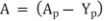
(1) For paragraph 106 (1) (c) of the Act, the carbon dioxide equivalent net abatement amount must be calculated as the quantity of methane emissions avoided as a consequence of the project, minus emissions from fuel used to operate the gas capture and combustion equipment, using the following formula:
| Equation 2.1 |
Where:
A = net greenhouse gas abatement due to the project, in tonnes of CO2-e.
 = gross quantity of emissions avoided as a consequence of the project in tonnes of CO2-e, as calculated in Equation 2.2.
 = emissions from fuel used to operate gas capture and combustion equipment for the purpose of the project, measured in tonnes of CO2‑e as calculated in Equation 4.1.
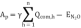
(2) Ap must be calculated as follows:
| Equation 2.2 |
Where:
= gross quantity of emissions avoided as a consequence of the project, in tonnes of CO2-e.
= the factor 6.784 x 10⁻⁴ x , converting cubic metres of methane to tonnes of CO2-e at standard conditions.
 = volume of methane destroyed by combustion device h, in cubic metres (m3) and capped according to section 3.9.
 = quantity of N2O emissions released as a result of methane destruction from all combustion devices, in tonnes of CO2-e.
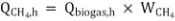
(3) Qcom,h must be calculated as follows:
Qcom, h  | Equation 2.3 |
Where:
Qcom, h = volume of methane destroyed by combustion device h, in cubic metres (m3) and capped according to section 3.9.
 = volume of methane sent to combustion device h, in cubic metres (m3) as calculated in Equation 2.4.
 = methane destruction efficiency for device h, as a fraction determined in accordance with section 3.10.
(4) must be calculated as follows:
| Equation 2.4 |
Where:
= volume of methane sent to combustion device h, in cubic metres (m3).
 = volume of biogas sent to combustion device h, adjusted to standard
 conditions, in cubic metres (m3), measured in accordance with Division 3.3.
 = the proportion of the volume of biogas that is methane.
(5) is, in accordance with the choice of a project proponent, either:
(a) 0.70; or
(b) measured in accordance with Division 3.3.
(6) Where volumetric measurements have not been adjusted to standard conditions based on actual temperature and pressure readings of the biogas,  must be multiplied by 0.97 before multiplying by .
3.9 Capping the volume of methane
(1) Qb (calculated using Equation 1.2) and  (calculated using Equation 2.3) must be estimated over the same time period and at least once every 12 months.
(2) If the value of the volume of methane destroyed by all combustion devices () is greater than the value for baseline methane emissions (Qb), the value for is deemed to be (Qb) in Equation 1.2.
3.10 Determining the methane destruction efficiency for a combustion device (DEh)
(1) Subject to subsection (2):
(a) the methane destruction efficiency for an open flare is 0.98; and
(b) for an internal combustion engine or an enclosed flare or a gas boiler, the methane destruction efficiency, may be either:
(i) 0.98; or
(ii) measured in accordance with Division 3.3.
(2) A methane destruction efficiency of 0.98 may only be used if the combustion device is installed and operated in accordance with the requirements set out by the device manufacturer.
(3) If the internal combustion engine or the gas boiler is shut down, has failed or is not being operated in accordance with the requirements set out by the device manufacturer, then the methane destruction efficiency for that hour is taken to be zero.
(4) For an open or an enclosed flare, if:
(a) there is no record of the temperature of the flare; or
(b) the recorded temperature is less than 500°C for any period exceeding 20 minutes in any particular hour,
then the methane destruction efficiency for that hour is taken to be zero.
Subdivision 3.2.4 Calculating nitrous oxide emissions
3.11 Calculating nitrous oxide emissions (
(1) Nitrous oxide emissions released as a result of methane destruction must be calculated using the following formula:

| Equation 2.5 |
Where:
EN2O = quantity of nitrous oxide emissions released as a result of methane destruction from all combustion devices, in tonnes of CO2‑e.
Qcom,h = capped volume of methane destroyed by combustion device h, in cubic metres (m3) as calculated in Equation 2.3.
EC = energy content of biogas, in gigajoules per cubic metre (GJ/ m3), as prescribed in the NGER (Measurement) Determination.
EFN2O = emissions factor for nitrous oxide emitted during the combustion of biogas in kilograms of CO2‑e per gigajoule of energy (kg CO2‑e /GJ) as prescribed in the NGER (Measurement) Determination.
Subdivision 3.2.5 Calculating emissions combusted in an internal combustion engine
3.12 Quantity of emissions combusted in an internal combustion engine – optional verification methods
(1) This section applies if a project uses an internal combustion engine for electricity generation which is fed by methane generated by the project activity.
(2) If subsection (1) applies, a project proponent must:
(a) determine the destruction efficiency of the internal combustion engine in accordance with section 3.10; and
(b) calculate the volume of methane combusted (Qcom,h), where h is the internal combustion engine, using Equation 2.3.
(3) In addition to subsection (2), a project proponent may verify Qcom,h by using the quantity of methane combusted by the internal combustion engine for electricity generation ( ). This may be calculated using Equation 3.1 and Equation 3.2.
Note To compare Qcom,h with Acom,ice for the purposes of subsection (3) the figure produced at 3.12 (2) (b) will need to be multiplied by 6.784 x 10⁻⁴ x  to obtain tonnes CO2-e.
(4) is to be calculated using the following formula:

| Equation 3.1 |
Where:
= amount of methane destroyed as a consequence of an internal combustion engine, in tonnes CO2-e.
QE = energy content of the methane sent to the internal combustion engine, in gigajoules (GJ) calculated in accordance with Equation 3.2.
CH4 conversion = 0.018.
factor
= global warming potential of methane as specified in the NGER Regulations.
(5) QE is to be calculated using the following formula:

| Equation 3.2 |
Where:
QE = quantity of energy produced as a result of methane combustion in the internal combustion engine, in gigajoules (GJ).
Electricity = the total amount of electricity produced by the internal produced combustion engine (supplied to the grid or used on-site)
in megawatt hours (MWh).
 = 3.6.
Eff = Electrical efficiency factor (as a fraction) for the internal combustion engine for conversion of energy to electricity, determined in accordance with subsection (6).
(6) Eff must be determined:
(a) in accordance with the manufacturer’s specifications for the equipment; or
(b) if there is no value specified by the manufacturer — a default of 0.36 must be used.
Subdivision 3.2.6 Calculating emissions from fuel used to operate the gas extraction system in the project (Yp)
3.13 Calculating emissions from fuel use (Yp)
(1) This section applies if fuel is used to operate the gas capture and combustion system used in the project.
(2) Yp must be calculated using the following formula:

| Equation 4.1 |
Where:
Yp = emissions from fuel used to operate gas capture and combustion equipment, measured in tonnes of CO2-e.
Ef = total emissions from fuel use, measured in tonnes of CO2-e in accordance with Equation 4.3.
(3) Ef must be calculated for each fuel type (i) and each greenhouse gas (j) (CO2, N2O, CH4) using the following formula:

| Equation 4.2 |
Where:
Ef= total emissions from fuel use, in tonnes of CO2-e.
i = fuel type
j = greenhouse gas type (CO2, N2O, CH4).
 = quantity of fuel type (i), measured in cubic metres, kilolitres or gigajoules.
 = energy content factor of fuel type (i), as prescribed in the NGER (Measurement) Determination, and used subject to subsection (4).
 = emission factor for each gas type (j) (which includes the effect of an oxidation factor) for fuel type (i) (in kilograms of CO2-e per gigajoule), as prescribed in the NGER (Measurement) Determination.
(4) If is measured in gigajoules, then is equal to 1.
(5) Total emissions from fuel used to operate the gas capture and combustion system  must be calculated as the sum of all emissions calculated using Equation 4.2, using the following formula:

| Equation 4.3 |
Where:
Ef = total emissions from fuel use, in tonnes of CO2-e.
j = greenhouse gas type (CO2, N2O, CH4).
i = fuel type.
n = number of fuel types (i).
N = number of gas types (j).
 = emissions from fuel type (i) of greenhouse gas (j) in tonnes of CO2-e.
Division 3.3 Data Collection
3.14 Data collection procedures and measurement frequency
A project proponent of an eligible offsets project must measure the matters specified in the following table, in the manner and frequency specified, for the purposes of calculating baseline methane emissions and project methane emissions.
Parameter | Description | Unit | Measurement Procedure | Measurement Frequency |
Tier 1 Method for calculating VS |
Milking cow numbers | Number of milking cows in an area where manure is collected and directed to the project pond. | Number | From herd recording data or farm records. | Once every 4-8 weeks as part of a herd recording event. |
Milk production | Average amount of milk produced per cow per day. | L/cow/day | - Sales receipts; or - Herd recording data; or - Milk meters. | - Milk collection frequency; or - With each herd recording event; or - Daily. |
Time milking cows spend in area (Ta) | For free-stall systems this is 21.6 hrs. For all others this is 2.4 unless weekly records are kept. | Hours | Recorded in log book. | If default value is not used, in accordance with the Effluent and Manure Management Database. |
Pre-treatment screening | Solid removal efficiency from effluent using pre-treatment methods | Fraction | In accordance with section 3.5. | For direct measurement, solids removal must be measured for a one week period for each season (four times per year) in accordance with the Effluent and Manure Management Database. |
Tier 2 Method for calculating VS - DGAS inputs |
Milking cow numbers | Number of milking cows in an area where manure is collected and directed to the project pond. | Number | From herd recording data or farm records. | Once every 4-8 weeks as part of a herd recording event. |
Milk production | The average amount of milk produced per cow per day. | L/cow/day | - Sales receipts; or - Herd recording data; or - Milk meters. | - Milk collection frequency; or - Each herd recording event; or - Daily |
Milking cow live weight | The average live weight of milking cows by class. | Kg | Herd records, farm scales or sale receipts. | Variable frequency as required by relevant calculations. |
Average lactation length | Average number of days per year an individual milking cow is in lactation | Days per year per milking cow | Herd recording data | - each herd recording event; or - Daily |
Time milking cows spend in area (Td) | Average hours per day milking cows spend in the area that effluent is collected and directed to project pond. | Hours | Recorded in log book. | - Milk collection frequency; or - Daily |
Feed used and type | For each type of feed mix used, the weight delivered to the facility minus the stockpile remaining each year. | Kg Feed type as defined within the worksheet entitled “Feed details” in the DGAS Calculator. | From delivery records. | Feed supplies recorded after delivery with balance calculated by season (spring/summer/autumn/winter), with home-grown pasture utilisation back-calculated. |
Fraction of effluent collected | Fraction of effluent sent to pre-treatment screening and the project pond after removing the average fraction of effluent spread daily on land from a sump | Fraction | Where no effluent is spread daily on land from a sump the value is 1. Where effluent is spread daily on land from a sump the fraction is estimated from sump design documents and log book records. | - Daily |
Pre-treatment screening | Solid removal efficiency from effluent using pre-treatment methods. | Fraction | In accordance with section 3.5. | For direct measurement solids removal needs to be measured for a one week period each season (four times per year). |
Tier 3 Method for calculating VS – Physical measurement |
Milking cow numbers | Number of milking cows in an area where manure is collected and directed to the project pond. | Number | Record numbers and enter into farm records. | Once every 4-8 weeks as part of a herd recording event. |
Time milking cows spend in area | The number of days per year and hours per day that cows spend in areas where effluent is collected for transfer to project ponds. | Days or Hours as appropriate | Recorded in log book. | In accordance with the Effluent and Manure Management Database. |
Volume of effluent | The volume of effluent entering the project pond. | L | - From sump volumes; or - Via suitable calibrated meter that can be used with effluent (e.g. non-contact magnetic meter). | Four times per year to cover all four seasons, with at least one full week of data collection per season. |
VS concentration of effluent | The VS concentration of effluent entering the project pond. | mg / L or g/L | A sufficient number of sub-samples to provide average effluent concentrations. Note: A typical sub-sampling protocol would involve the collection of at least 40 sub-samples collected throughout the whole pump-out period of an agitated sump. | Four times per year to cover all four seasons, with at least one full week of data collection per season. |
Data collection for abatement calculations |
Qbiogas,h | Quantity of biogas sent to combustion device h. | m3 | The standards and protocol for measurement are outlined below. | Continuous monitoring – an average value in a time interval not greater than one hour. |
DEh | Methane destruction efficiency for device h. | % | Flares Measured efficiency (enclosed flares only): Duplicate compliance testing, measured every 6 months, by a NATA accredited emission stack testing company, using a method based on US EPA Method 18 or US EPA Method 3 C; Default (open or enclosed flares): a default destruction efficiency of 0.98 is applied Internal combustion engine Measured efficiency: Duplicate compliance testing, measured every 6 months, by a NATA accredited emission stack testing company, using a method based on US EPA Method 18; or US EPA Method 3C. or A default destruction efficiency is applied (0.98) Gas Boiler A default destruction efficiency is applied (0.98) | Every 6 months, if using measured efficiency by a testing company or not applicable if using the default value. |
WCH4 | The proportion of the volume of biogas that is methane, as a percentage. | m3CH4/ m3 | A default methane proportion may be applied. The default methane proportion of the gas is 70%. Otherwise the methane fraction must be measured, as described below. 1.Continuous, using an inline gas analyser; or 2. Monthly, where samples of the biogas are collected and sent to a laboratory for analysis. | Continuous (inline gas analyser) or monthly sampling (laboratory analysis). |
Qi | Quantity of fuel used for the operation of gas capture and combustion equipment | For liquid fuels, measured in kilolitres (kL), or for gaseous fuels, measured in m3 unless otherwise specified in the NGER (Measurement) Determination. | For each fuel used (diesel, LPG, etc.) the amount must be estimated as a proportion of totals for the project activities. Manufacturer’s specifications will assist with these estimates for the gas capture and combustion component. | If estimated from invoices, then estimate from total amount of fuel used per annum |
Electricity produced | Quantity of electricity produced by methane combustion in internal combustion engine generator. | MWh | Meter data, recording electricity produced by internal combustion engine generator (if electricity is used on site). The accuracy of the meter used must be equivalent of a revenue meter; or meter data recording electricity sent to the grid. | Total amount of electricity produced during the reporting period. |
Eff | The electrical efficiency factor of the internal combustion engine generator | % | - As specified by the manufacturer of the generator in the technical manual for the equipment; or - a default value of 36% . | N/A – assumed value. |
3.15 Measuring the quantity of biogas sent to combustion device h (Qbiogas,h)
Qbiogas, h must be measured in accordance with the following requirements:
(1) Gas flow must be measured:
(a) at the delivery location of the gaseous fuel;
(b) using a gas volumetric flow meter that uses a continuous monitoring system; and
(c) in cubic metres per hour (m3 per hour).
(2) Subject to subsection (1), gas flow must be measured using equipment that:
(a) is rated for use with a process gas/biogas/dirty stream;
(b) is rated for use at the expected flow rate and pressure;
(c) is designed for use in the anticipated operating temperature range; and
(d) the meter is to be accurate to +/‑ 5% for flow measurement.
(3) Gas flow must be continuously recorded and integrated using an integration device that is isolated from the flow computer in such a way that if the computer fails, the integration device will retain the last reading, or the previously stored information, that was on the computer immediately before the failure.
(4) All measurements must comply with the National Measurement Act.
3.16 Measuring the proportion of volume of biogas that is methane ( )
)
(1) The percentage of methane in biogas (),is either:
(a) the default value prescribed in the NGER (Measurement) Determination; or
(b) the composition of biogas at the project site measured using an inline gas analyser; or
(c) the composition of biogas resulting from the analysis of biogas samples in a NATA accredited laboratory.
(2) Where subsection (1) (b) applies, the following requirements apply:
(a) paired values of the methane fraction of the gas and gas flow that are averaged for the same time interval must be used in the calculation of emission reductions; and
(b) measurement of the methane fraction must occur at the same time as flow measurement.
(3) Where subsection (1) (c) applies, the following requirements apply:
(a) gas composition samples must be taken at the delivery location of the gaseous fuel;
(b) gas composition samples must be taken on a regular basis, occurring no less than once per month;
(c) the sampling vessel must be set up to provide a time period for the instrument to stabilise and carry out initial checks in accordance with the instrument provided by the manufacturer; and
(d) there must be no leaks in the sampling train or between the sampling train and the instrument; and
(e) gas samples must be analysed using US EPA Method 3 gas chromatography or mass spectrometry.
Part 4 Monitoring and Reporting
Division 4.1 Project monitoring
4.1 Application
For the purposes of subsection 106 (3) of the Act, a project proponent of an eligible offsets project must comply with the monitoring, record-keeping and reporting requirements of this Part.
4.2 Quality assurance and quality control
(1) All monitoring instruments must be:
(a) cleaned and inspected on a regular basis to ensure the equipment operates within an accuracy threshold of +/- 5%, with the activities performed and the “as found/as left” condition of the equipment documented;
(b) field checked for calibration accuracy, with the per cent drift documented, within two months before the end of the reporting period by a third-party technician:
(i) using an appropriate instrument or apparatus; or
(ii) as per the manufacturer’s guidance; and
(c) calibrated by the manufacturer or an accredited third-party calibration service with the frequency recommended by the manufacturer’s guidance, or every 5 years, whichever occurs with greater frequency.
(2) Field checks of monitoring instruments must determine whether the instrument reads measurement within the accuracy threshold of +/-5%.
(3) If a field check of a monitoring instrument determines that its accuracy is outside of the accuracy threshold of +/-5% then the instrument must be calibrated by the manufacturer or an accredited third-party calibration service. The calibration must ensure that the instrument reads measurement within the accuracy threshold of +/-5%.
(4) All combustion devices must be installed, operated and maintained in accordance with the manufacturer’s guidance.
Division 4.2 Record-keeping requirements
4.3 Information for calculating the baseline
Tier one method for calculating VS
(1) A project proponent that elects to use the tier 1 method for calculating VS must make and keep records of:
(a) cow numbers and classes;
(b) milk production and length of lactation/dry-off period for seasonal operation;
(c) time cows spend in areas where effluent is collected for transfer to project ponds;
(d) efficiency of pre-treatment (screening) systems;
(e) number of project ponds;
(f) pond dimensions; and
(g) calculation of VS.
Tier 2 Method for calculating VS
(2) A project proponent that elects to use the tier 2 method for calculating VS must make and keep records of:
(a) cow number and classes;
(b) milk production and length of lactation/dry-off period for seasonal operation;
(c) time cows spend in areas where effluent is collected for transfer to project ponds;
(d) type and quantity of feed;
(e) number of project ponds;
(f) pond dimensions;
(g) calculation of VS;
(h) value of emissions of methane from ponds used in the project; and
(i) total methane emissions from all cattle classes, calculated using the Faecal Methane Workbook of the DGAS Calculator.
Tier 3 Method for calculating VS
(3) A project proponent that elects to use the tier 3 method for calculating VS must make and keep records of:
(a) cow number and classes;
(b) time cows spend in areas where effluent is collected for transfer to project ponds;
(c) volume of effluent;
(d) laboratory analysis sheet of VS concentration;
(e) number of project ponds;
(f) pond dimensions; and
(g) calculation of VS.
4.4 General information
(1) In addition to the information specified in section 4.3, the following information must be made and kept:
(a) receipts and specifications relating to the gas capture and combustion equipment;
(b) all maintenance records relevant to the gas capture system, monitoring equipment and combustion devices;
(c) logs of operations of the gas management system including notation of all shut-downs, start-ups, process adjustments;
(d) evidence of corrective measures taken if instruments do not meet performance specifications;
(e) independent audit records and results; and
(f) if default values are not used, NATA certificates from the testing laboratory as evidence of measured methane destruction efficiency.
4.5 Information about combustion devices
(1) The following information must be recorded and kept in relation to each combustion device:
(a) the model, serial number, and calibration procedures for the device;
(b) combustion device monitoring data for the device; and
(c) combustion device calibration data for the device.
4.6 Information about monitoring devices
(1) The following information must be kept in relation to monitoring instruments:
(a) the model, serial number and calibration procedures for the instrument; and
(b) gas flow meter calibration data for each flow meter.
4.7 Information about gas composition
(1) The following information must be kept in relation to on-site analysis of gas composition:
(a) the model, serial number and calibration procedures for the gas analyser;
(b) gas analyser calibration data for each gas analyser; and
(c) gas quality data, including particulate content and humidity.
4.8 Information about direct and indirect measurement
(1) The following information must be kept in relation to direct and indirect measurement:
(a) records of any raw data and site observations relating to the gas capture and combustion system and parameters entered into DGAS;
(b) all values and calculations used in baseline calculations;
(c) all values and calculations used in to calculate net greenhouse gas abatement;
(d) monthly and annual CO2-e tonnage calculations;
(e) electronic recording of values of logged primary parameters for each measurement interval, for each meter, including:
(i) gas flow data for each flow meter;
(ii) temperature data from temperature measurement device for each device; and
(iii) methane content of gas for each measurement.
(f) for paragraph (e) (iii), the following information must be included:
(i) the date, time and location of measurement;
(ii) notes of non-compliance to performance specifications; and
(iii) remedial actions taken to correct instrument.
(g) evidence of fuel use; and
(h) if Equations 3.1 and 3.2 are used, evidence of the amount of the electricity produced by the internal combustion engine generator.
Division 4.3 Offsets report requirements
4.9 Information required in offsets reports
(1) The following information is required to be provided in every offsets report:
(a) net greenhouse gas abatement number (A);
(c) quantity of methane generated under baseline conditions in tonnes of CO2‑e (Eb);
(d) total volume of methane sent to combustion devices, in cubic metres (sum of  );
);
(e) destruction efficiencies of combustion devices (if default values not used) (DEh);
(f) total amount of fuel used by the project, in kilolitres (kL), cubic metres (m3), or kilowatt hours (kWh); and
(g) electrical efficiency of (Eff) of the internal combustion engine generator.
Division 4.4 Reporting under section 77A of the Act
4.10 Division compatible with calculations
For subsection 77A (2) of the Act, the division of the overall project must not be incompatible with the calculation of the carbon dioxide equivalent net abatement amount for a project for a reporting period under this Determination.
Endnotes
Endnote 1—About the endnotes
The endnotes provide information about this compilation and the compiled law.
The following endnotes are included in every compilation:
Endnote 1—About the endnotes
Endnote 2—Abbreviation key
Endnote 3—Legislation history
Endnote 4—Amendment history
Endnotes about misdescribed amendments and other matters are included in a compilation only as necessary.
Abbreviation key—Endnote 2
The abbreviation key sets out abbreviations that may be used in the endnotes.
Legislation history and amendment history—Endnotes 3 and 4
Amending laws are annotated in the legislation history and amendment history.
The legislation history in endnote 3 provides information about each law that has amended (or will amend) the compiled law. The information includes commencement details for amending laws and details of any application, saving or transitional provisions that are not included in this compilation.
The amendment history in endnote 4 provides information about amendments at the provision (generally section or equivalent) level. It also includes information about any provision of the compiled law that has been repealed in accordance with a provision of the law.
Misdescribed amendments
A misdescribed amendment is an amendment that does not accurately describe the amendment to be made. If, despite the misdescription, the amendment can be given effect as intended, the amendment is incorporated into the compiled law and the abbreviation “(md)” added to the details of the amendment included in the amendment history.
If a misdescribed amendment cannot be given effect as intended, the amendment is set out in the endnotes.
Endnote 2—Abbreviation key
A = Act | orig = original |
ad = added or inserted | par = paragraph(s)/subparagraph(s) |
am = amended | /sub‑subparagraph(s) |
amdt = amendment | pres = present |
c = clause(s) | prev = previous |
C[x] = Compilation No. x | (prev…) = previously |
Ch = Chapter(s) | Pt = Part(s) |
def = definition(s) | r = regulation(s)/rule(s) |
Dict = Dictionary | Reg = Regulation/Regulations |
disallowed = disallowed by Parliament | reloc = relocated |
Div = Division(s) | renum = renumbered |
exp = expires/expired or ceases/ceased to have | rep = repealed |
effect | rs = repealed and substituted |
F = Federal Register of Legislative Instruments | s = section(s)/subsection(s) |
gaz = gazette | Sch = Schedule(s) |
LI = Legislative Instrument | Sdiv = Subdivision(s) |
LIA = Legislative Instruments Act 2003 | SLI = Select Legislative Instrument |
(md) = misdescribed amendment | SR = Statutory Rules |
mod = modified/modification | Sub‑Ch = Sub‑Chapter(s) |
No. = Number(s) | SubPt = Subpart(s) |
o = order(s) | underlining = whole or part not |
Ord = Ordinance | commenced or to be commenced |
Endnote 3—Legislation history
Name | FRLI registration | Commencement | Application, saving and transitional provisions |
Carbon Credits (Carbon Farming Initiative) (Destruction of Methane Generated from Dairy Manure in Covered Anaerobic Ponds) Methodology Determination 2012 | 21 Dec 2012 (F2012L02571) | 1 July 2010 (s 1.2) | |
Carbon Credits (Carbon Farming Initiative—Emissions Reduction Fund) Methodology Determination Variation 2015 | 26 June 2015 (F2015L00954) | 1 July 2015 (s 2) | Carbon Credits (Carbon Farming Initiative) Act 2011, s 126 |
Endnote 4—Amendment history
Provision affected | How affected |
Part 1 | |
s 1.2A................... | ad F2015L00954 |
s 1.3.................... | am F2015L00954 |
s 1.4.................... | am F2015L00954 |
Part 3 | |
Division 3.1 | |
s 3.1.................... | am F2015L00954 |
s 3.3.................... | am F2015L00954 |
Division 3.2 | |
Subdivision 3.2.5 | |
s 3.12................... | am F2015L00954 |
Part 4 | |
Division 4.3 | |
s 4.9.................... | am F2015L00954 |
Division 4.4............... | ad F2015L00954 |
s 4.10................... | ad F2015L00954 |