CONTENTS
0. legislative provisions..............................................
1. SCOPE.........................................................
2. APPLICABILITY AND IMPLEMENTATION.........................
3. DEFINITIONS...................................................
4. REQUIREMENTS................................................
5. EXEMPTIONS AND ALTERNATIVE PROCEDURES..................
6. SUPPLEMENTARY GENERAL REQUIREMENTS....................
7. ALTERNATIVE STANDARDS.....................................
8. NOTES.........................................................
0. legislative provisions
0.1. NAME OF STANDARD
0.1.1. This Standard is the Vehicle Standard (Australian Design Rule 51/00 – Filament Lamps) 2006.
0.1.2. This Standard may also be cited as Australian Design Rule 51/00 — Filament Lamps.
0.2. COMMENCEMENT
0.2.1. This Standard commences on the day after it is registered.
0.3. REPEAL
0.3.1. This Standard repeals each vehicle standard with the name Australian Design Rule 51/00 — Filament Lamps that is:
(a) made under section 7 of the Motor Vehicle Standards Act 1989; and
(b) in force at the commencement of this Standard.
0.3.2. This Standard also repeals each instrument made under section 7 of the Motor Vehicle Standards Act 1989 that creates a vehicle standard with the name Australian Design Rule 51/00 — Filament Lamps, if there are no other vehicle standards created by that instrument, or amendments to vehicle standards made by that instrument, that are still in force at the commencement of this Standard.
- SCOPE
This Australian Design Rule (ADR) prescribes the dimensional and photometric requirements for filament lamps which ensure interchangeability and correct functioning when installed in a lamp unit.
2. APPLICABILITY AND IMPLEMENTATION
2.1. The circumstances under which lamps are mandatory, optional, or prohibited are set out in either ADRs 13/.., 19/… or 67/….
3. DEFINITIONS
3.1. Refer to paragraph 2.1 of Appendix A.
4. REQUIREMENTS
4.1. Devices complying with the technical requirements of Appendix A, part 5 Exemptions and Alternative Procedures and part 6 Supplementary General Requirements shall be accepted as complying with this vehicle standard.
5. EXEMPTIONS AND ALTERNATIVE PROCEDURES
5.1. The following provisions of Appendix A do not apply.
5.1.1. Administrative provisions
Section 2.2 Application for approval
Section 2.4 Approval
Section 3.8 Observation concerning selective yellow colour.
Section 6 Production definitely discontinued
Section 7 Names and addresses of technical services responsible for conducting approval tests, and of administrative departments
Section 8 Transitional provisions
Annexes
Annex 2 Communication concerning the approval (or refusal or withdrawal of approval or production definitely discontinued) of a type of filament lamp pursuant to Regulation No. 37
Annex 3 Example of the arrangement of the approval mark
6. SUPPLEMENTARY GENERAL REQUIREMENTS
The following general requirements are supplementary to the requirements of Appendix A:
6.1. The requirements and procedures set out in Annexes 6 and 7 of Appendix A are acceptable for the purposes of demonstrating compliance with the technical requirements of this rule.
6.2. In paragraph 3.10 of Appendix A, it is permissible to use filament lamps other than standard filament lamps listed in Annex 1 for photometric tests specified in lighting component ADRs which refer to ADR 51/… provided those filament lamps comply with paragraph 7.2 and other requirements of this Rule except for Annex 1.
6.3. In cases where it is not possible to meet the requirements of paragraph 2.3, Inscriptions, information necessary to ensure traceability of replaceable components affecting the photometric performance must be provided. This information shall be marked on the bulb, or the cap, or permanently marked on the lamp body.
7. ALTERNATIVE STANDARDS
7.1. The technical requirements of any of the editions of United Nations –Economic Commission (UN ECE) for Europe Regulation No. 37 - UNIFORM PROVISIONS CONCERNING THE APPROVAL OF FILAMENT LAMPS FOR USE IN APPROVED LAMP UNITS OF POWER DRIVEN VEHICLES AND OF THEIR TRAILERS, up to and including the edition incorporating the 03 series of amendments are deemed to be equivalent to the technical requirements of this rule.
7.2. Filament lamps conforming to FMVSS 108 Lamps Reflective Devices and Associated Equipment, SAE J573 Dec89 Miniature Lamp Bulbs and JIS C 7506 – 1994 Lamp Bulbs for Motor Vehicles, may be used in lighting and light signalling devices in which case the photometric test must be conducted as referenced in paragraphs 6.2 and 6.3 using either
7.2.1. a standard filament lamp which has been selected as specified in the relevant standard referenced in clause 7.2 above; or
7.2.2. where selection of standard filament lamp is not addressed in the standard chosen from those required in clause 7.2 above, then the light and light signalling device must be capable of meeting those photometric requirements using any of the filament lamps of the selected type that conform to the specifications in that standard.
8. NOTES
8.1. In place of Regulation No 48 where referenced in Appendix A, read ADR 13/00.
Appendix A
UN-ECE REGULATION NO. 37/03
UNIFORM PROVISIONS CONCERNING THE APPROVAL OF FILAMENT LAMPS FOR USE IN APPROVED LAMP UNITS OF POWER DRIVEN VEHICLES AND THEIR TRAILERS
NOTE:
In view of recent changes to the Regulation, text containing Supplements 8 and 9 have not been incorporated in the main Regulation document. Supplements 8 and 9 have been attached at the end of R37/03. Changes in the texts of Supplements 8 and 9 will be incorporated into the Regulation when the consolidated document is available from the UN-ECE.
Regulation No. 37
UNIFORM PROVISIONS CONCERNING THE APPROVAL OF FILAMENT LAMPS FOR USE IN APPROVED LAMP UNITS OF POWER DRIVEN VEHICLES AND OF THEIR TRAILERS
CONTENTS
REGULATION
1. Scope
2. Administrative provisions
2.1. Definitions
2.2. Application for approval
2.3. Inscriptions
2.4. Approval
3. Technical requirements
3.1. Definitions
3.2. General specifications
3.3. Manufacture
3.4. Tests
3.5. Filament position and dimensions
3.6. Colour
3.7. The UV radiation of a halogen filament
3.8. lampObservation concerning selective-yellow colour
3.9. Check on optical quality
3.10. Standard filament lamps
4. Conformity of production
5. Penalties for non-conformity of production
6. Production definitely discontinued
7. Names and addresses of technical services responsible for conducting approval tests, and of administrative departments
8. Transitional provisions
ANNEXES
Annex 1 Sheets
Sheets H1
Sheets H2
Sheets H3
Sheets H4
Sheets P21W
Sheet P21/4W
Sheets P21/5W
Sheet R5W
Sheet R10W
Sheet C5W
Sheets C21W (filament lamp for reversing lamp)
Sheet T4W
Sheet W5W
Sheet W3W
Sheets S1 and S2 (filament lamps for motor cycles)
Sheet S3 (filament lamp for mopeds)
CONTENTS (continued)
Sheets S4 (filament lamp for mopeds)
Sheets HS1
Sheets HS2 (halogen filament lamp for mopeds)
Sheets PY21W (amber coloured filament lamp)
Sheet H6W
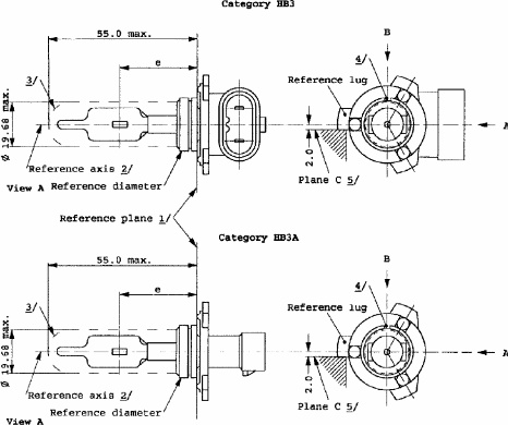
Sheets HB3
Sheets HB4
Sheet T1.4W
Sheet H7
Sheets H27W
Sheets P27W
Sheets P27W/7W
Sheet WY5W
Sheets H21W
Sheets W21W
Sheets W21/5W
Sheets W2.3W
Sheets H8
Sheets W16W
Sheets HIR1
Sheets PY27/7W
Sheets HIR2
Sheets H9
Sheets H10
Annex 2 Communication concerning the approval (or extension or refusal or withdrawal of approval or production definitely discontinued) of a type of filament lamp pursuant to Regulation No. 37
Annex 3 Example of the arrangement of the approval mark
Annex 4 Luminous centre and shapes of lamp filaments
Annex 5 Checking the colour and transmission of selective-yellow bulbs and outer bulbs and amber bulbs Annex 6 Minimum requirements for quality control procedures by the manufacturer
Annex 7 Sampling and compliance levels for manufacturer tests records
Annex 8 Minimum requirements for spot checks by the administrative authority
Annex 9 Compliance approved by spot check
Regulation No. 37
UNIFORM PROVISIONS CONCERNING THE APPROVAL OF FILAMENT LAMPS FOR USE IN APPROVED LAMP UNITS OF POWER DRIVEN VEHICLES AND OF THEIR TRAILERS
1. SCOPE
This Regulation applies to filament lamps shown in annex 1 and intended for use in approved lamp units of power driven vehicles and of their trailers.
2. ADMINISTRATIVE PROVISIONS
2.1. Definitions
2.1.1. Definition of "category"
The term "category" is used in this Regulation to describe different basic design of standardized filament lamps. Each category has a specific designation, as for example: "F1", "P21W", "T4W".
2.1.2. Definition of "type"
Filament lamps of different "types" are lamps within the same category which differ in such essential respects as:
2.1.2.1. trade name or mark;
2.1.2.2. bulb design, in so far as these differences affect the optical results;
2.1.2.3. bulb colour
A selective-yellow bulb or an additional selective-yellow outer bulb, solely intended to change the colour but not the other characteristics of a colourless filament lamp, does not constitute a change of type of the filament lamp;
2.1.2.4. rated voltage.
2.2. Application for approval
2.2.1. The application for approval shall be submitted by the owner of the trade name or mark, or by his duly accredited representative.
2.2.2. Every application for approval shall be accompanied (see also para. 2.4.2.) by:
2.2.2.1. drawings in triplicate, sufficiently detailed to permit identification of the type;
2.2.2.2. a brief technical description;
2.2.2.3. five samples of each colour which has been applied for.
2.2.3. In the case of a type of filament lamp differing only by the trade name or mark from a type that has already been approved it shall be sufficient to submit:
2.2.3.1. a declaration by the lamp manufacturer that the type submitted is identical (except in the trade name or mark) with and has been produced by the same manufacturer as, the type already approved, the latter being identified by its approval code;
2.2.3.2. two samples bearing the new trade name or mark.
2.2.4. The competent authority shall verify the existence of satisfactory arrangements for ensuring effective control of the conformity of production before type approval is granted.
2.3. Inscriptions
2.3.1. Filament lamps submitted for approval shall bear on the cap or bulb:
2.3.1.1. the trade name or mark of the applicant;
2.3.1.2. the rated voltage;
2.3.1.3. the international designation of the relevant category;
2.3.1.4. the rated wattage (in the sequence, principal filament/secondary filament for dual- filament lamps); this need not be indicated separately if it is part of the international designation of the relevant filament lamp category;
2.3.1.5. a space of sufficient size to accommodate the approval mark.
2.3.2. The space mentioned in paragraph 2.3.1.5. above shall be indicated in the drawings accompanying the application for approval.
2.3.3. Halogen filament lamps meeting the requirements of paragraph 3.7. below shall be marked with a "U".
2.3.4. Other inscriptions than those covered by paragraphs 2.3.1. and 2.4.3. may be affixed, on the condition that they do not adversely affect the luminous characteristics.
2.4. Approval
2.4.1. If all the samples of a type of filament lamp which are submitted in pursuance of paragraphs 2.2.2.3. or 2.2.3.2. above meet the requirements of this Regulation, approval shall be granted.
2.4.2. An approval code shall be assigned to each type approved. Its first character (at present 2 corresponding to the 02 series of amendments which entered into force on 27 October 1983 and to the 03 series of amendments, not requiring changes in the approval number, which entered into force on 1 June 1984) shall indicate the series of amendments incorporating the most recent major technical amendments made to the Regulation at the time of issue of the approval. This will be followed by an identification code comprising not more than two characters. Only the arabic numerals and capital letters listed in footnote shall be used. The same Contracting Party may not assign the same code to another type of filament lamp. Notice of approval or of extension or refusal or withdrawal of approval or production definitely discontinued of a type of filament lamp pursuant to this Regulation shall be communicated to the Parties to the 1958 Agreement which apply this Regulation by means of a form conforming to the model in annex 2 to this Regulation. If the applicant so desires the approval code may be assigned to the colourless and to the selective-yellow filament lamp (see para. 2.1.2.3.).
2.4.3. To every filament lamp conforming to a type approved under this Regulation there shall be affixed in the space referred to in paragraph 2.3.1.5., in addition to the inscriptions required under paragraph 2.3.1., an international approval mark consisting of:
2.4.3.1. a truncated circle surrounding the letter "E" followed by the distinguishing number of the country which has granted approval;
2.4.3.2. the approval code, placed close to the truncated circle.
2.4.4. If the applicant has obtained the same approval code for several trade names or marks, one or more of them will suffice to meet the requirements of paragraph 2.3.1.1.
2.4.5. The marks and inscriptions specified in paragraphs 2.3.1. and 2.4.3. shall be clearly legible and be indelible.
2.4.6. Annex 3 to this Regulation gives an example of arrangement of the approval mark.
3. TECHNICAL REQUIREMENTS
3.1. Definitions
3.1.1. Rated voltage: voltage (in V) marked on the filament lamp;
3.1.2. Rated wattage: wattage (in W) marked on the filament lamp which may be incorporated into the international designation of the relevant category;
3.1.3. Test voltage: voltage, at the filament lamp terminals for which the electrical and photometric characteristics of the filament lamp are intended and are to be tested;
3.1.4. Objective values: values to be achieved, within the specified tolerances, when the filament lamp is supplied with current at its test voltage;
3.1.5. Standard filament lamp: a lamp with colourless bulb (except for amber filament lamps) and with reduced dimensional tolerances, used for the testing of lighting devices. Standard filament lamps are specified in only one voltage rating for each category;
3.1.6. Reference luminous flux: specified luminous flux of a standard filament lamp to which the optical characteristics of a lighting device shall be referred;
3.1.7. Measuring luminous flux: specified value of the luminous flux for testing a filament lamp in the standard headlamp as specified in paragraph 3.8.;
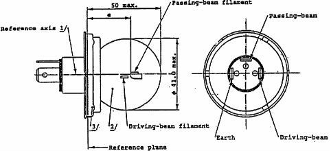
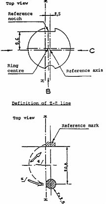
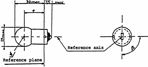
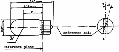
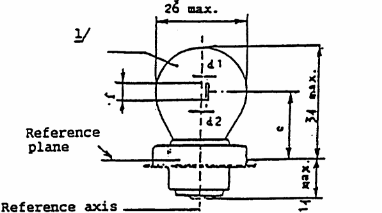
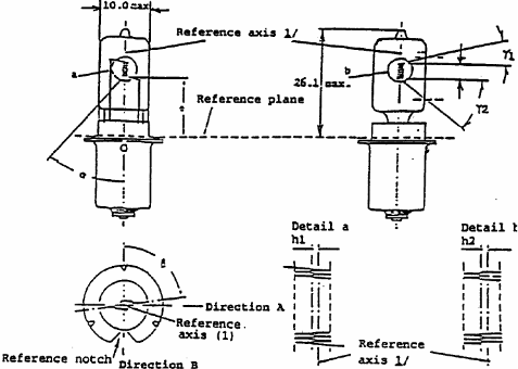
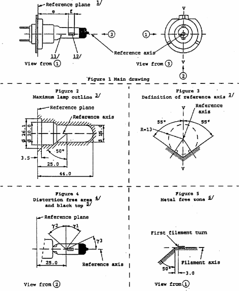
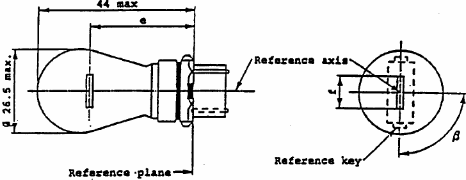
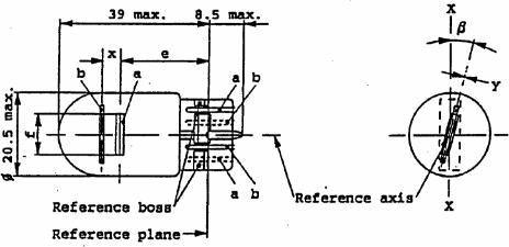
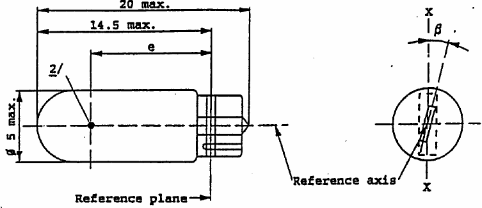
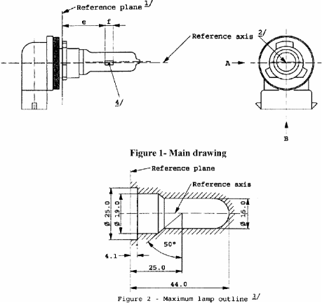
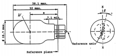
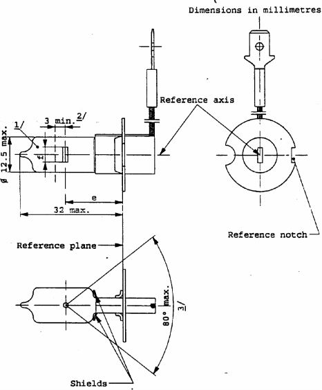
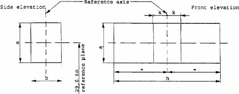
3.1.8. Reference axis: an axis defined with reference to the cap and to which certain dimensions of the filament lamp are referred;
3.1.9. Reference plane: a plane defined with reference to the cap and to which certain dimensions of the filament lamp are referred.
3.2. General specifications
3.2.1. Each sample submitted shall conform to the relevant specifications of this Regulation.
3.2.2. Filament lamps shall be so designed as to be and to remain in good working order when in normal use. They shall moreover exhibit no fault in design or manufacture.
3.3. Manufacture
3.3.1. Filament lamp bulbs shall exhibit no scores or spots which might impair their efficiency and their optical performance.
3.3.2. Filament lamps shall be equipped with standard caps complying with the cap data sheets of IEC Publication 61, third edition, as specified on the individual lamp data sheets of annex 1.
3.3.3. The cap shall be strong and firmly secured to the bulb.
3.3.4. To ascertain whether filament lamps conform to the requirements of paragraphs 3.3.1. to 3.3.3. above, a visual inspection, a dimension check and, where necessary, a trial fitting shall be carried out.
3.4. Tests
3.4.1. Filament lamps shall first be aged at their test voltage for approximately one hour. For dual-filament lamps, each filament shall be aged separately.
3.4.2. In the case of a coloured bulb after the aging period corresponding to paragraph 3.4.1. the surface of the bulb shall be lightly wiped with a cotton cloth soaked in a mixture of 70vol.% of n-heptane and 30vol.% of toluol. After about five minutes, the surface shall be inspected visually. It must not show any apparent changes.
3.4.3. The position and dimensions of the filaments shall be measured with the filament lamps being supplied with current at from 90% to 100% of the test voltage.
3.4.4. Unless otherwise specified, electrical and photometric measurements shall be carried out at the test voltage.
3.4.5. Electrical measurements shall be carried out with instruments of at least class 0.2.
3.4.6. The luminous flux specified on the filament lamp data sheets of annex 1 is valid for filament lamps emitting white light, unless a special colour is stated there.
In the case where selective-yellow colour is allowed, the luminous flux of the filament lamp with selective-yellow outer bulb shall be at least 85% of the specified luminous flux of the relevant filament lamp with colourless bulb.
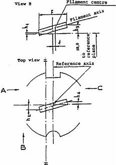
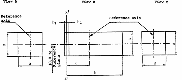
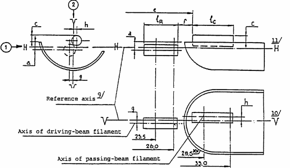
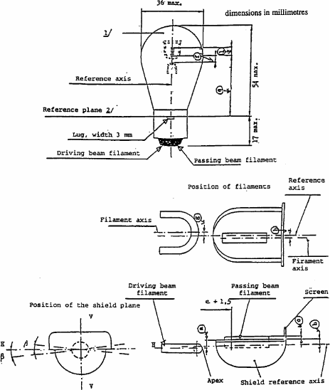
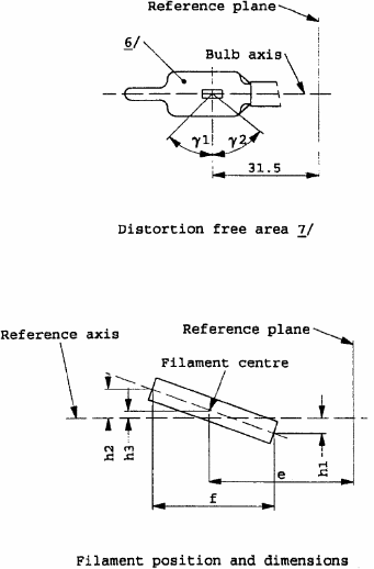
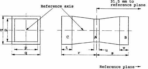
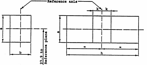
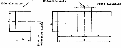
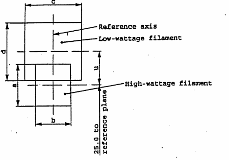
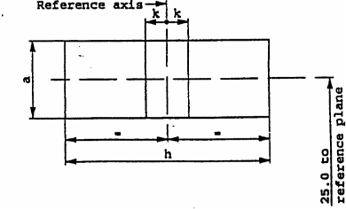
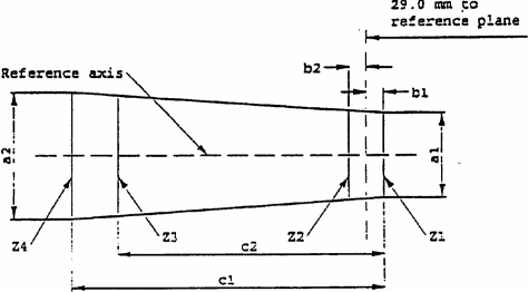
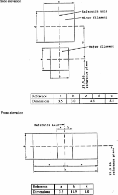
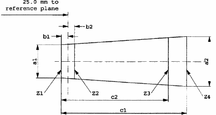
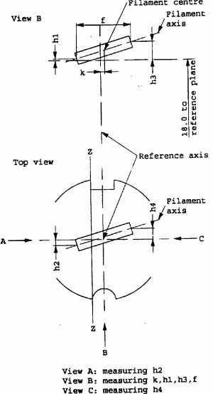
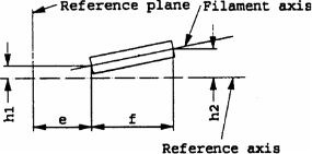
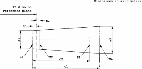
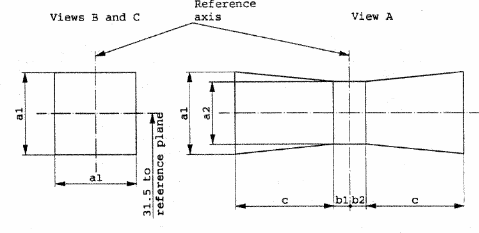
3.5. Filament position and dimensions
3.5.1. The geometric shapes of the filaments shall in principle be as specified on the lamp data sheets of annex 1.
3.5.2. For line filaments the correct position and shape shall be checked as specified in the relevant data sheets.
3.5.3. If the filament is shown on the lamp data sheet in at least one view as a point, the position of the luminous centre shall be determined in conformity with annex 4.
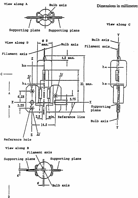
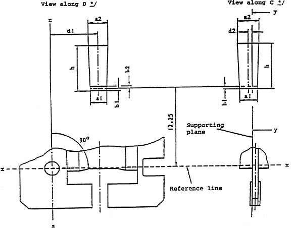
3.5.4. The length of a line filament shall be determined by its ends, defined - unless otherwise specified on the relevant data sheet - as the apices of the first and the last filament turn as seen in projection perpendicular to the reference axis of the lamp. Such an apex shall comply with the requirement that the angle formed by the legs shall not exceed 90 degrees . In the case of coiled-coil filaments the apices of the secondary turns shall be taken into account.
3.5.4.1. For axial filaments the extreme position of the apices considered shall be determined by rotating the filament lamp about its reference axis. The length shall then be measured in a direction parallel to the reference axis.
3.5.4.2. For transverse filaments the filament axis shall be placed perpendicular to the direction of projection. The length shall be measured in a direction perpendicular to the reference axis.
3.6. Colour
3.6.1. The bulb of the filament lamp shall be colourless, unless otherwise prescribed on the relevant data sheet.
3.6.2. The colorimetric characteristics, expressed in CIE chromaticity coordinates, shall lie within the following limits: finished filament lamps with selective yellow bulb or outer bulb
limit towards red: y > 0.138 + 0.580x;
limit towards green: y < 1.29x - 0.100;
limit towards white: y > -x + 0.966;
(y > -x + 0.940 and y = 0.440 for front fog lamps);
limit towards spectral value: y < -x + 0.992;
finished filament lamps with amber bulb
limit towards red: y > 0.398
limit towards green: y < 0.429
limit towards white: z < 0.007
3.6.3. The colour and the transmission of the bulb of filament lamps emitting coloured light shall be measured by the method specified in annex 5.
3.7. The UV radiation of a halogen filament lamp shall be such that:
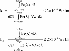
where: Ee (lamda) [W/nm] is the spectral distribution of the radiant flux; V (lamda) [l] is the spectral luminous efficiency;
lamda [nm] is the wave length.
This value shall be calculated using intervals of five nanometre.
3.8. Observation concerning selective-yellow colour
An approval of a filament lamp type under this Regulation may be granted, pursuant to paragraph 3.6 above, for a filament lamp with a colourless as well as a selective-yellow bulb or outer bulb; article 3 of the Agreement to which this Regulation is annexed shall not prevent the Contracting Parties from prohibiting, on vehicles registered by them, lamps emitting either white or selective-yellow light.
3.9. Check on optical quality
(Applies solely to filament lamps with two filaments for headlamps emitting an asymmetrical passing beam).
3.9.1. This check of optical quality shall be carried out at a voltage such that the measuring luminous flux is obtained; the specifications of paragraph 3.4.6. are to be observed accordingly.
3.9.2. For 12V filament lamps emitting white light:
The sample which most nearly conforms to the requirements laid down for the standard filament lamp shall be tested in a standard headlamp as specified in paragraph 3.8.5. and it shall be verified whether the assembly comprising the aforesaid headlamp and the filament lamp being tested meets the light-distribution requirements laid down for the passing beam in the relevant Regulation.
3.9.3. For 6V and 24V filament lamps emitting white light: The sample which most nearly conforms to the nominal dimension values shall be tested in a standard headlamp as specified in paragraph 3.8.5. and it shall be verified whether the assembly comprising the aforesaid headlamp and the filament lamp being tested meets the light-distribution requirements laid down for the passing-beam in the relevant Regulation. Deviations not exceeding 10% of the minimum values will be acceptable.
3.9.4. Filament lamps having a selective-yellow bulb or outer bulb shall be tested in the same manner as described in paragraphs 3.8.2. and 3.8.3. in a standard headlamp as specified in paragraph 3.8.5. to ensure that the illumination complies with at least 85%, for 12V filament lamps, and at least 77%, for 6V and 24V filament lamps, with the minimum values of the light-distribution requirements laid down for the passing beam in the relevant Regulation. The maximum illumination limits remain unchanged.
In the case of a filament lamp having a selective-yellow bulb this test shall be left out if the approval is also given to the same type of filament lamp emitting white light.
3.9.5. A headlamp shall be deemed to be a standard headlamp if:
3.9.5.1. it satisfies the pertinent conditions of approval;
3.9.5.2. it has an effective diameter of not less than 160mm;
3.9.5.3. with a standard filament lamp it produces at the various points and in the various zones specified for the headlamp type concerned, illumination equal to:
3.9.5.3.1. not more than 90% of the maximum limits and
3.9.5.3.2. not less than 120% of the minimum limits prescribed for the headlamp type concerned.
3.10. Standard filament lamps
Standard filament lamps for photometric tests of headlamps and light-signalling appliances are specified on the relevant data sheets of annex 1. Standard filament lamps shall have colourless bulbs (except for amber filament lamps) and be specified for only one rated voltage.
4. CONFORMITY OF PRODUCTION
4.1. Filament lamps approved to this Regulation shall be so manufactured as to conform to the type approved by meeting the inscriptions and technical requirements set forth in paragraph 3 above and annexes 1, 3 and 4 to this Regulation.
4.2. In order to verify that the requirements of paragraph 4.1. are met, suitable controls of the production shall be carried out.
4.3. The holder of the approval shall in particular:
4.3.1. ensure existence of procedures for the effective control of the quality of products,
4.3.2. have access to the control equipment necessary for checking the conformity to each approved type,
4.3.3. ensure that data of test results are recorded and that related documents shall remain available for a period to be determined in accordance with the administrative service,
4.3.4. analyse the results of each type of test, applying criteria of annex 7, in order to verify and ensure the stability of the product characteristics making allowance for variation of an industrial production,
4.3.5. ensure that for each type of filament lamp, at least the tests prescribed in annex 6 to this Regulation are carried out,
4.3.6. ensure that any collecting of samples giving evidence of non-conformity with the type of test considered shall give rise to another sampling and another test. All the necessary steps shall be taken to re-establish the conformity of the corresponding production.
4.4. The competent authority which has granted type-approval may at any time verify the conformity control methods applicable to each production unit.
4.4.1. In every inspection, the test books and production survey records shall be presented to the visiting inspector.
4.4.2. The inspector may take samples at random which will be tested in the manufacturer's laboratory. The minimum number of samples may be determined according to the results of the manufacturer's own verification.
4.4.3. When the quality level appears unsatisfactory or when it seems necessary to verify the validity of the tests carried out in application of paragraph 4.4.2. above, the inspector shall select samples, to be sent to the technical service which has conducted the type approval tests.
4.4.4. The competent authority may carry out any tests prescribed in this Regulation. Where the competent authority decides to carry out spot checks, criteria of annexes 8 and 9 to this Regulation shall be applied.
4.4.5. The normal frequency of inspections authorized by the competent authority shall be one every two years. In the case where negative results are recorded during one of these visits, the competent authority shall ensure that all necessary steps are taken to re- establish the conformity of production as rapidly as possible.
5. PENALTIES FOR NON-CONFORMITY OF PRODUCTION
5.1. The approval granted in respect of a type of filament lamp pursuant to this Regulation may be withdrawn if the requirements are not met or if a filament lamp bearing the approval mark does not conform to the type approved.
5.2. If a Contracting Party to the Agreement applying this Regulation withdraws an approval it has previously granted, it shall forthwith so notify the other Contracting Parties applying this Regulation by means of a communication form conforming to the model in annex 2 to this Regulation.
6. PRODUCTION DEFINITELY DISCONTINUED
If the holder of the approval completely ceases to manufacture a type of filament lamp approved in accordance with this Regulation, he shall so inform the authority which granted the approval. Upon receiving the relevant communication, that authority shall inform thereof the other Parties to the 1958 Agreement applying this Regulation by means of a communication form conforming to the model in annex 2 to this Regulation.
7. NAMES AND ADDRESSES OF TECHNICAL SERVICES RESPONSIBLE FOR CONDUCTING APPROVAL TESTS, AND OF ADMINISTRATIVE DEPARTMENTS
The Parties to the 1958 Agreement which apply this Regulation shall communicate to the United Nations Secretariat the names and addresses of the technical services responsible for conducting approval tests and of the administrative departments which grant approval and to which forms certifying approval or extension or refusal or withdrawal of approval, or production definitely discontinued issued in other countries, are to be sent.
8. TRANSITIONAL PROVISIONS
8.1. Approvals granted under the preceding series of amendments shall remain valid, except that for conformity of production, current production filament lamps shall comply with the requirements of the latest series of amendments starting 12 months from the date of application of this amendment.
8.2. The correspondence between the former designations and the new ones is indicated in the following table:
Old designation | New designation in the 03 series of amendments |
P25-1 | P21W |
P25-2 | P21/5W |
R19/5 | R5W |
R19/10 | R10W |
C11 | C5W |
C15 | C21W |
T8/4 | T4W |
W10/5 | W5W |
W10/3 | W3W |