CONTENTS
0. legislative provisions..............................................
Purpose and SCOPE.....................................................
APPLICABILITY.......................................................
5.1. DEFINITIONS...................................................
5.2. REQUIREMENTS................................................
5.3. ‘SASH GUIDE' REQUIREMENTS...................................
5.4. LOCATION OF ‘ANCHOR POINTS' AND 'SASH LOCATION POINT’
5.5. TESTING OF 'ANCHORAGES'
5.6. test OF 'SASH GUIDE'
5.7. SEATING POSITIONS............................................
5.8. Not used........................................................
5.9. 'AREA A' AND 'AREA B'
5.10. GENERAL REQUIREMENTS FOR `ANCHORAGES' FOR VEHICLE CATEGORIES MD3, MD4, ME, NB2 AND NC ONLY
5.11. REQUIREMENTS FOR 'CHID RESTRAINT ANCHORAGES' (MA, MB AND MD VEHICLES ONLY)
5.12. ALTERNATIVE STANDARDS.....................................
NOTES ...............................................................
0. legislative provisions
0.1. NAME OF STANDARD
0.1.1. This Standard is the Vehicle Standard (Australian Design Rule 5/00 – Anchorages for Seat Belts and Child Restraints) 2006.
0.1.2. This Standard may also be cited as Australian Design Rule 5/00 — Anchorages for Seat Belts and Child Restraints.
0.2. COMMENCEMENT
0.2.1. This Standard commences on the day after it is registered.
0.3. REPEAL
0.3.1. This Standard repeals each vehicle standard with the name Australian Design Rule 5/00 — Anchorages for Seat Belts and Child Restraints that is:
(a) made under section 7 of the Motor Vehicle Standards Act 1989; and
(b) in force at the commencement of this Standard.
0.3.2. This Standard also repeals each instrument made under section 7 of the Motor Vehicle Standards Act 1989 that creates a vehicle standard with the name Australian Design Rule 5/00 — Anchorages for Seat Belts and Child Restraints, if there are no other vehicle standards created by that instrument, or amendments to vehicle standards made by that instrument, that are still in force at the commencement of this Standard.
Purpose and SCOPE
This Australian Design Rule (ADR) is a part of the Australian motor vehicle standards system and is a national standard for the purpose of the Motor Vehicle Standards Act 1989.
The function of this Australian Design Rule is to specify requirements for 'Anchorages' for both 'Seat Belt Assemblies' and 'Child Restraints' so that they may be adequately secured to the vehicle structure or 'Seat' and will meet comfort requirements in use.
APPLICABILITY
This ADR applies to the design and construction of vehicle as set out in the table hereunder. The Package 11 issue of /00 also corrects the Table on page 3.
Vehicle Category | ADR Category Code | UNECE Category Code * | Manufactured on or After | Acceptable Prior Rules |
Moped 2 wheels | LA | L1 | Not Applicable | |
Moped 3 wheels | LB | L2 | Not Applicable | |
Motor cycle | LC | L3 | Not Applicable | |
Motor cycle and sidecar | LD | L4 | Not Applicable | |
Motor tricycle | LE | L5 | Not Applicable | |
Passenger car | MA | M1 | 1 July 1988 | Nil |
Forward-control passenger vehicle | MB | M1 | 1 July 1988 | Nil |
Off-road passenger vehicle | MC | M1 | 1 July 1988 | Nil |
Light omnibus | MD | M2 | | |
| up to 3.5 tonnes ‘GVM’ and up to 12 seats | MD1 | | 1 July 1988 | Nil |
| up to 3.5 tonnes ‘GVM’ and more than 12 seats | MD2 | | 1 July 1988 | Nil |
| over 3.5 tonnes and up to 4.5 tonnes ‘GVM’ | MD3 | | 1 July 1988 | Nil |
| over 4.5 tonnes and up to 5 tonnes ‘GVM’ | MD4 | | 1 July 1988 | Nil |
Heavy omnibus | ME | M3 | 1 July 1988 | Nil |
Light goods vehicle | NA | N1 | 1 July 1988 | Nil |
Medium goods vehicle | NB | N2 | | |
| over 3.5 tonnes up to 4.5 tonnes ‘GVM’ | NB1 | | 1 July 1988 | Nil |
| over 4.5 tonnes up to 12 tonnes ‘GVM’ | NB2 | | 1 July 1988 | Nil |
Heavy goods vehicle | NC | N3 | 1 July 1988 | Nil |
Very light trailer | TA | O1 | Not Applicable | |
Light trailer | TB | O2 | Not Applicable | |
Medium trailer | TC | O3 | Not Applicable | |
Heavy trailer | TD | O4 | Not Applicable | |
5.1. DEFINITIONS
5.1.0. Refer to Vehicle Standard (Australian Design Rule Definitions and Vehicle Categories) 2005.
5.1.1. 'Anchor Point' - the point where the centre of the 'Strap' passes into the 'Anchor Fitting' or changes direction at the 'Anchor Fitting' except that in the case of 'Anchor Fittings' which are designed to pivot or are attached by a single bolt, the 'Anchor Point' shall be regarded as the intersection of the axis of rotation, or the centreline of the bolt, with the surface of the vehicle.
5.1.2. Not used.
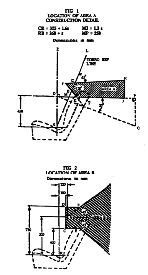
5.1.3. 'Area A' and 'Area B' - areas established in accordance with Section 5.9 (Figures 1 and 2).
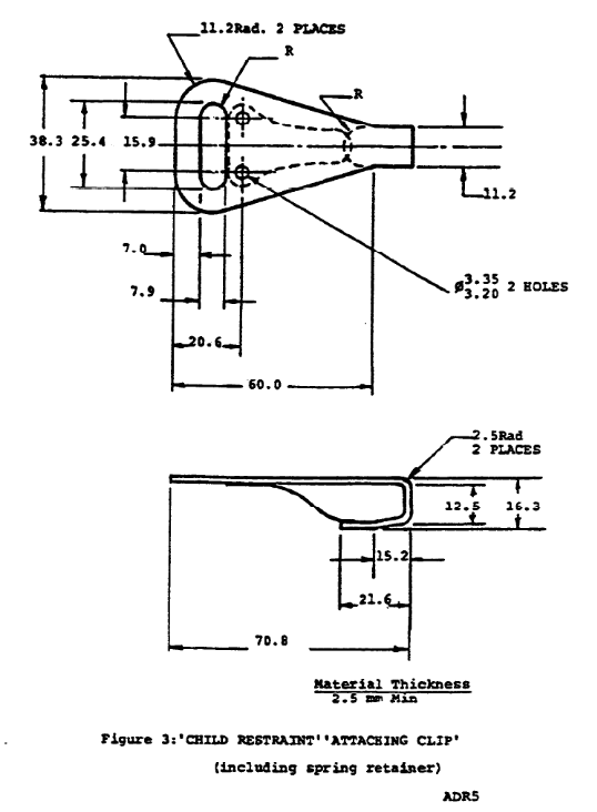
5.1.4. 'Attaching Clip' - the device shown in Figure 3 which is designed to be attached to the 'Anchor Fitting'
5.1.5. 'Child Restraint - a device consisting of a harness, (with or without a chair), or an enclosure arrangement of energy absorbing material, or any other device, which is intended to minimize the risk of bodily injury to a child in an accident.
5.1.6. 'Child Restraint Anchor Fitting' - the fitting shown in Figure 4 which is attached to the 'Child Restraint Anchorage'. #
5.1.7. 'Design line of Action' - The centreline of the 'Child Restraint' attachment, in side elevation and with 'Seat' installed, from the 'Shoulder Point' to the 'Child Restraint Anchor Fitting'.
5.1.8. 'Harness Torso Anchorage' - an 'Anchorage' designed to facilitate upper torso restraint using a harness assembly.
5.1.9. 'Lap Anchorage' - An 'Anchorage' provided to facilitate pelvic restraint
5.1.10. 'Pelvis Reference Locus’ - the locus of a point fixed relative to the 'Seat', coincident with the 'Pelvis Reference Point' when the 'Seat' is in the rearmost design position and extending over the design or riding range of 'Seat' trave.
5.1.11. 'Pelvis Reference Point' - a point used in simulating the correct position of a lap 'Strap' or the lap `Strap' of a 'Lap-Sash Belt'. It is the point which is located at a height of 95 mm above and 70 mm 'Forward' of the 'Seating Reference Point'.
5.1.12. 'Permanent Structure' - structure that cannot be readily removed within a short time using hand tools.
5.1.13. 'Rear Seat (MB/MD1)' any front facing ‘Seat’ in a forward-control passenger vehicle (MB) or light omnibus (MDI) which lies to the rear of the seating positions of the driver, or the front passenger(s).
5.1.14. 'Sash Location Point' - the point where the centreline of the `Strap' first changes direction after leaving the 'Upper Torso Reference Point'.
5.1.15. 'Seat Back Angle' - the angle between the 'Torso Reference Line' and the vertical line through the 'Seating Reference Point’.
5.1.16. 'Shoulder Point' - a point 300 mm above the ‘Seating Reference Point', measured along the ‘Torso Reference Line’ and representing the 'Shoulder Point' of a '50th Percentile 6 Year Old Child’.
5.1.17. 'Spacer' - an annular block used to raise the position of the 'Child Restraint Anchor Fitting(s)' shown in Figure 5.
5.1.18. 'Transverse Distance S' - the shortest transverse distance in mm from the 'Seating Reference Plane' to the point under consideration.
5.1.19. 'Upper Torso Reference Point' - an arbitrary point representing the last point of contact of a sash 'Strap' on a torso when the 'Seat' back is adjusted to the design 'Seat Back Angle'. It is located at a height of 530 mm above the 'Seating Reference Point' measured along the 'Torso Reference Line’ 60 mm 'Forward' of the 'Torso Reference Line' when measured normal to the ‘Torso Reference Line' and 120 mm from the 'Seating Reference Plane' when measured normal to the 'Seating Reference Plane' and towards the 'Sash Guide’.
'upper anchor fitting' - see 'Child Restraint Anchor Fitting'
'upper anchorage' - see 'Child Restraint Anchorage'.
5.2. REQUIREMENTS
5.2.0. General
5.2.0.1. Seat belt 'Anchorages'
5.2.0.1.1. Vehicle categories MA, MB, MC, MD1, MD2, NA and NB1 shall comply with Clauses 5.2.1 to 5.9.
5.2.0.1.2. Vehicle categories MD3. MD4. ME. NB2 and NC shall comply with either.
5.2.0.1.2.1. Section 5.10; or
5.2.0.1.2.2. Clause 5.2.0.1.1 except that the required 'Anchorage’ strength is only 45 kN.
5.2.0.1.3. It is recommended that each `Anchorage' should accept a 7/16 inch - 20 UNF - 2A threaded steel bolt
5.2.0.2. 'Child Restraint Anchorages'
5.2.0.2.1. Vehicle categories MA, MB and MD1 shall comply with Section 5.11.
5.2.1. Requirements for ‘Anchorages’
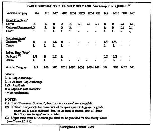
5.2.1.1. Seat belt 'Anchorages' shall be provided for all seating positions (as established in accordance with Section 5.7) except for light omnibuses (MD2) where 'Anchorages' are required only for front seating positions. (An indicative summary of 'Anchorage' and seat belt type applicability requirements, for guidance only, is given in the following table)
5.2.2. Design of 'Anchorages' for 'Seat Belt Assemblies' - All 'Anchorages' shall be designed so that 'Seat Belt Assemblies' may be replaced readily. Any 'Anchorage' may be designed to receive more than one 'Anchor Fitting'.
5.2.3. Pelvic Restraint - For each seating position 2 'Lap Anchorages' shall be available.
5.2.4. Upper Torso Restraint
5.2.4.1.1. Not used
5.2.4.1.2. For all front facing front 'Outboard Seating Positions', provision shall be made for upper torso restraints.
5.2.4.2. For all front facing and rear facing 'Outboard Seating Positions' specified in Clause 5.2.1.1 other than specified in Clauses 5.2.4.1.2 and 5.2.4.3, provision shall be made for upper torso restraints provided that there is 'Permanent Structure' other than the 'Seat' above a horizontal plane located 350 mm above the 'Seating Reference Point' and 'Rearward' of a vertical transverse plane through the 'Upper Torso Reference Paint'. If the design provides for a 'Harness Belt', one or 2 ‘Harness Torso Anchorages' shall be provided.
5.2.4.3. Optional ‘Anchorages’
5.2.4.3.1. Not used
5.2.4.3.2. For MA, MC, MD2, NA and NB1 vehicles, provision of upper torso restraint shall be optional in the case of 'Outboard Seating Positions' where the 'Seat' is designed to provide adjustment for conversion of occupant space to luggage or goods space and such seating positions are not the driver's or front passenger seating positions or the seating positions immediately to the rear thereof.
5.2.4.4. Upper torso restraint shall not be provided for side-facing seating positions
5.2.5. Location of 'Anchorages'
The location of ‘Anchorages' shall be such that the locations of their appropriate 'Anchor Points' meet the requirements of Section 5.4.
5.2.6. Strength of 'Anchorages'
5.2.6.1. Testing of 'Anchorages' shall be in accordance with the requirements of Section 5.5.
5.2.6.2. Each 'Anchorage' shall be capable of supporting, for not less than one second, the load imposed on it by a body block subjected to the appropriate load as specified in Clause 5.2.6.4, the body block being attached to the 'Anchorage’ under test and another 'Anchorage' as specified in Clause 5.5.4.1.
5.2.6.3. An ‘Anchorage’ may be tested in a test relevant to that 'Anchorage' only or in combination with tests on other 'Anchorages'.
5.2.6.4. The loads to be applied to body blocks for testing of 'Anchorages' shall be as specified in the following table:

5.2.7. Symmetrical 'Anchorages' - Except where the requirements of Clause 5.2.8 apply, in cases where 2 ‘Anchorages' are identical in design and symmetrically located relative to the vertical longitudinal plane through the geometric centre of the vehicle, a test on one ‘Anchorage' shall be considered also as a test on the other.
5.2.8. Adjacent and Multiple 'Anchorages'
5.2.8.1. For the purposes of this Clause, a single ‘Anchorage' which provides for 2 seating positions shall be regarded as 'Anchorages'.
5.2.8.2. All 'Anchorages' which are provided for different seating positions and which are separated by not more than 200 mm shall be tested simultaneously, except that
5.2.8.2.1. if one seating position faces to the front and the other to the rear, the 'Anchorages' shall be tested independently, and
5.2.8.2.2. notwithstanding the requirements of Clause 5.2.6, the minimum total load to be applied to the body block or blocks for testing one 'Anchorage' common to both pelvic and upper torso restraint may be limited to 17.7 kN
5.2.9. 'Anchorages' on Pillars - In cases where a 'Lap Anchorage' and either a 'Final Torso Anchorage' or a ‘Sash Guide' which is a load bearing 'Sash Guide' as described in Clause 5.3.1.2, are both located on a pillar which is in the vicinity of the front 'Seat' back and which joins the roof so, the under body structure, the pillar shall be capable of supporting for not less than one second, the loads imposed on it by body blocks subjected to loads totalling 26.6 kN such that
5.2.9.1. not less than 13.3 kN is applied to the body block attached to the 'Final Torso Anchorage' or 'Sash Guide' as appropriate and another 'Anchorage' as specified in Clause 5.5.4.1;
and
5.2.9.2. the balance of the load is applied to a body block attached to the 'Lap Anchorage' and another 'Anchorage' as specified in Clause 5.3.4.1.
5.2.9.3. Testing to the requirements of this Clause may be incorporated in a test conducted in accordance with the provisions of Clause 5.2.6.
5.2.10. Adjustable Upper Torso 'Anchorages' - In cases where one or more 'Anchorages' are adjustable, the ‘Anchorages' shall be capable of meeting the relevant strength requirements of Clause 5.2.6, 5.2.8 and 5.2.9 with the 'Anchorages' in any position of adjustment
5.2.11. Adjustable 'Sash Location Points' - In cases when an ‘Anchorage' is fitted with a 'Sash Guide' system incorporating an adjustable 'Sash Location Point', the 'Anchorage' shall be capable of meeting the relevant strength requirements of Clauses 5.2.6, 5.2.8 and 5.2.9 with the `Sash Location Point' set in any position of adjustment.
5.3. ‘SASH GUIDE' REQUIREMENTS
5.3.1. General
5.3.1.1. The 'Sash Guide' shall be nominated by the vehicle 'Manufacturer' as being either.
5.3.1.1.1. a component of a 'Seat Belt Assembly';
or
5.3.1.1.2. not a component of a 'Seat Belt Assembly'. This latter category shall include those 'Sash Guides' which are not intended to be replaced when the 'Seat Belt Assembly' is replaced.
5.3.1.2. For the purpose of this Rule, a load bearing 'Sash Guide' means a 'Sash Guide' which remains integral with its supporting structure and retains the 'Strap' under the following loading conditions:
5.3.1.2.1. the 'Anchorage' test loads specified in Clause 5.2.6; or
5.3.1.2.2. in the case where the 'Sash Guide' is a component of a 'Seat Belt Assembly', both the Dynamic Testing Procedure of the Australian Design Rule for "Seat Belts" and the static strength of assembly test of Australian Standard E35-1970, 'Seat Belt Assemblies for Motor Vehicles’ or Australian Standard AS 2597.10 - 1983, *Determination of Static Strength and Dummy Displacement" as specified in the Australian
Design Rule for "Seat Belts".
5.3.1.3. In the case where the 'Sash Guide' is not a component of a 'Seat Belt Assembly' (as nominated in Clause 5.3.1.1.2), then the 'Sash Guide’ shall comply with Clause 5.3.8 as well as with the following Clauses of the Australian
Design Rule for "Seat Belts" (where applicable) as if the 'Sash Guide' were part of the 'Seat Belt Assembly': Clause 4.2.7 (but also excluding Clauses 5, 9 and 14 of Australian Standard 2596.1983, "Seat Belt Assemblies for Motor Vehicles" or Clause 3, 7 and 11 of Australian Standard E35 Pt. 1-1970, "Seat Belt Assemblies; Motor Vehicles"), Clause 4.3.3 and Clause 4.3.1.
5.3.2. Provision - A 'Sash Guide' shall be provided for each seating position to be fitted with a 'Lap-Sash Belt'.
5.3.3. Strength - Except in cases where the ‘Anchor Fitting' at the 'Final Torso Anchorage' is the 'Sash Guide', the 'Sash Guide' shall, when tested in accordance with the requirements of Clause 5.6 withstand the loads in such a way that after application and removal of the loads there is no substantial deformation and the 'Sash Guide' remains integral with its supporting structure and continues to retain the 'Strap'.
5.3.4. 'Seat' Back - In cases where the 'Seat' back is ‘Sash Guide' device the design of the 'Seat' back shall be such that it is not possible for the 'Strap' to fall below the lower boundary of 'Area A’ at any point to greater than 300 mm from the 'Seating Referent Plane'. If this requirement is met by the use of positive restraining device incorporated with or attached to the 'Seat' back then the device shall be designed to withstand a load of 50 N applied in a horizontal transverse direction away from the 'Seating Referent Plane'.
5.3.5. Design of 'Sash Guide' Device - In cases where the 'Sash Guide' which includes the 'Sash Location Point' is a load bearing 'Sash Guide', it shall retain the 'Strap' so that either:
5.3.5.1. the 'Strap' cannot be removed from the 'Sash Guide' without the use of tools; or
5.3.5.2. the 'Strap' may be removed but returns to its design position when loads are applied.
5.3.6. 'Sash Location Point' - The 'Sash Guide' shall be so designed that the `Sash Location Point' meets the location requirements of Clause 5.4.2.
5.3.7. Failure of 'Sash Guide' Devices - In cases when one or more 'Sash Guide' in the 'Sash Guide' system are not load beating 'Sash Guides', the design of the system shall be such that in the installed design position:
5.3.7.1. the point of the first load bearing 'Sash Guide’ where the centreline of the strap first changes direction after leaving the preceding 'Sash Guide' shall be in 'Area A' or 'Area B’ and
5.3.7.2. the maximum length of 'Strap' required to pass from that point to the 'Upper Torso Reference Point' via the 'Sash Guide' system shall not exceed by more than 60 mm the true distance between those points.
5.3.8. Deflection of 'Sash Guides'
5.3.8.1. In the case of a 'Sash Guide' system where the 'Sash Guide' which includes the 'Sash Location Point' is a load bearing 'Sash Guide', and is not a component of a 'Seat Belt Assembly' (as nominated in Clause 5.3.1) the design shall be such that
5.3.8.1.1. in the case of a 'Sash Guide’ with a non adjustable 'Sash Location Paint', the 'Sash Guide’ system shall comply with Clauses 5.3.8.2 and 5.3.8.3; and
5.3.8.1.2. in the case of a 'Sash Guide’ system with an adjustable 'Sash Location Point', the 'Sash Guide’ system shall comply with Clauses 5.3.8.2 and 5.3.8.4 with the 'Sash Location Point' set in any position of adjustment.
5.3.8.2. When a load is applied as specified in Clause 5.6.2, `Sash Guide’ deflection shall not reduce, by more than 60 mm, the actual length of ‘Strap’ measured along the ‘Strap’ centreline between the 'Upper Torso Reference Pont' and the final ‘Anchor Pout'.
5.3.8.3. When a load is applied as specified in Clause 5.6.2, the displaced 'Sash Location Point' shall lie in 'Area A' or ‘Area B’.
5.3.8.4. When a load is applied as specified in Clause 5.6.2 the displaced 'Sash Location Point' shall not be below horizontal transverse plane DJ of ‘Area A' or horizontal transverse plane CE of ‘Area B' whichever is the lower.
5.3.9. Effect of ‘Seat' Back Adjustment - In cases where the 'Seat’ back is provided with at least one point of adjustment between the design 'Seat Back Angle' and 30o inclusive, the requirements of Clauses 5.3.7.2 and 5.3.8.1 shall be met when the 'Upper Torso Reference Point' is determined with the 'Seat' back adjusted not to the design 'Seat Back Angle' but to the greatest available 'Seat Back Angle' up to including 30o.
5.4. LOCATION OF ‘ANCHOR POINTS' AND 'SASH LOCATION POINT’
5.4.1. Lap 'Anchor Points'
5.4.1.1. The 2 lap 'Anchor Points' provided for a particular seating position shall be on opposite sides of the 'Seating Reference Plane’ in such a way that the sum of distances measured normal to the `Seating Reference Plane’ is not less than 165 mm.
5.4.1.2. The lines joining the lap 'Anchor Point' to the extreme points on the 'Pelvis Reference, Locus' shall be inclined to the horizontal at angles of not less than 25o nor more than 80o when viewed normal to the 'Seating Reference Plane’.
5.4.1.3. In cases where the line representing the centreline of the 'Strap' is not a straight line when viewed normal to the 'Seating Reference Plane' then:
5.4.1.3.1. with the ‘Seat’ in its foremost driving or riding position the line passing through the foremost point on the ‘Pelvis Reference Locus’ and extending ‘Rearwards’ to the first point of contact with the 'Seat' or other device shall be inclined to the horizontal at an angle of not less than 25o; and
5.4.1.3.2. with the `Seat' in the rearmost driving or riding position the distance from the 'Pelvis Reference Point' to the lap 'Anchor Point' measured along the centreline of the ‘Strap’ shall not exceed by more than 60 mm the distance from the 'Pelvis Reference Point' to the lap ‘Anchor Point', except in the cases where the system is so designed that when tested in accordance with the load requirements of Clause 5.2.6 the components of the vehicle or 'Seat' which cause the centreline of the 'Strap' between the lap 'Anchor Point' and the ‘Pelvis Reference Point' to vary from a straight line, do not defect or fail in such a manner that the effective length of the 'Strap' measured along the centreline between the lap ‘Anchor Point' and the 'Pelvis Reference Point' is reduced by more than 60 mm.
5.4.2. 'Sash Location Point'
5.4.2.1. For both conditions of load specified in Clause 5.6.1 the following requirements shall be met:
5.4.2.1.1. the `Sash Location Pont' shall be at least 140 mm from the 'Seating Reference Plane'; and
5.4.2.1.2. the 'Sash Location Point' shall lie in `Area A'.
5.4.2.2. Notwithstanding the requirements of Clause 5.4.2.1 the 'Sash Location Point' may be adjustable for comfort provided that
5.4.2.2.1. at least one point in the range of adjustment shall permit the 'Sash Location Point' to comply with the requirements of Clause 5.4.2.1;
5.4.2.2.2. no point of adjustment shall cause the 'Sash Location Point' to be below horizontal transverse plane DJ of 'Area A' for both condition of load specified in Clause 5.6.1; and
5.4.2.2.3. the 'Sash Location Point' shall be adjustable without the use of tools.
5.4.3. Harness 'Anchor Points'
5.4.3.1. In cases where only one harness 'Anchorage’ is provided for a particular seating position, the harness 'Anchor Point' shall be
5.4.3.1.1. 'Rearward' of transverse plane inclined at the same angle as the ‘Torso Reference Line’. and 500 mm horizontally 'Rearward' from the ‘Seating Reference Plane’
5.4.3.1.2. not more than 50 mm from the 'Seating Reference Plane'; and
5.4.3.1.3. within 'Area B' but without the location requirements of Clause 5.9.2.1.
5.4.3.2. In cases where 2 harness 'Anchorages' are provided for a particular seating position, the 2 'Anchor Points' shall be located
5.4.3.2.1. 'Rearward' of a transverse plane inclined at the same angle as the ‘Torso Reference Line’ and 75 mm horizontally 'Rearward' from the 'Seating Reference Point’;
5.4.3.2.2. either side of the `Seating Reference Plane' in such a way that the distances from the 'Seating Reference Plane' do not differ by more than 100 mm;
5.4.3.2.3. such that the transverse separation does not exceed 300 mm, and is either greater than 25 mm or is less than 250 mm by not more than half the horizontal distance from either 'Anchor Point' to the transverse place through the 'Torso Reference Line'; and
5.4.3.2.4. within 'Area B' but without the transverse location requirements of Clause 5.9.2.1.
5.5. TESTING OF 'ANCHORAGES'
5.5.1. Installation of Doors
Except in cases where the vehicle complies with the Australian Design Rule for "Door Latches and Hinges”, testing shall be carried out with the vehicle doors open or removed.
5.5.2. Installation of 'Seats'
The appropriate 'Seats' shall be installed for the tests and located in their rearmost driving or riding position and with the 'Seat' back adjusted to the design 'Seat Back Angle' except that in cases where the line of pull could not contact a particular portion of the 'Seat' then that portion may be removed.
5.5.3. Body Blocks
Loads shall be transmitted by the use of body blocks.
5.5.4. Loading of Body Blocks
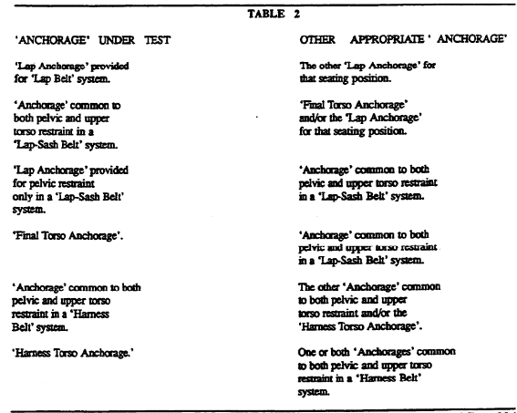
5.5.4.1. Each body block shall be restrained by attachments which are representative of a seat belt passing around the body block and connected to the 'Anchorage' under test and another appropriate 'Anchorage' as described in the following Table 2, by fittings that are representative of the actual 'Anchor Fittings' designed for each 'Anchorage'.
5.5.4.2. In cases where one 'Anchorage' is a 'Final Torso Anchorage', the attachment restraining the body block shall pass through the 'Sash Guide' system except that
5.5.4.2.1. it may by-pass any 'Sash Guide' which is not a load bearing 'Sash Guide'; and
5.5.4.2.2. a load bearing 'Sash Guide’ which is a component of a 'Seat Belt Assembly' (as nominated in Clause 5.3.1) may be replaced by a representative component of sufficient strength to withstand the load requirements of Clause 5.2.6.
5.5.5. Direction of Loading
5.5.5.1. In the case of front and rear facing 'Seats', the direction of load to the body blocks shall be:
5.5.5.1.1. 'Forward' of the seating position;
5.5.5.1.2. parallel to the 'Seating Reference Plane'
5.5.5.1.3. in the case of pelvic restraint, at an angle above the horizontal of not less than 5o nor more than 50o; and
5.5.5.1.4. in the case of upper torso restraint, at an angle above the horizontal of not less than 0o nor more than 20o.
5.5.5.2. In the case of side facing 'Seats', the direction of load to the body block attached to the 'Lap ‘Anchorages' shall be:
5.5.5.2.1. in a direction towards the front of the vehicle:
5.5.5.2.2. in a vertical plane inclined inboard to a vertical longitudinal plane relative to the vehicle by not more than 20o; and
5.5.5.2.3. at an angle to the horizontal of not less than 5o nor more than 50o.
5.6. test OF 'SASH GUIDE'
5.6.1. With the upper torso 'Strap' installed in the vehicle, tensile loads of 5 N and 900 N shall be applied to it in a direction from the appropriate 'Sash Location Point' towards the 'Upper Torso Reference Point'.
5.6.2. With the upper torso 'Strap' installed in the vehicle, a tensile load of not less than 8.5 kN shall be applied to the 'Strap' in a direction from the appropriate 'Sash Location Point' towards the 'Upper Torso Reference Point'.
5.7. SEATING POSITIONS
5.7.1. Single 'Seats'- A 'Seat' shall be regarded as providing for one seating position only if the effective cushion width is less than 820 mm.
5.7.2. Multiple 'Seats' - If the effective cushion width is 820 mm or more, the number of seating positions shall be the number of complete multiples of 410 mm unless the nature of obstructions: or peculiarities of design results in the 'Seat' being 'Approved' for a lesser number of seating positions.
5.7.2.1. Where a 'Seat' with an effective cushion width, as determined by Clause 5.7.3, of 1230 mm or more has its ‘Seat’ cushion and 'Seat' back so contoured as to provide one or 2 clearly identifiable seating positions, the 'Seat' will be considered as providing for 2 seating positions only if one or more of the following conditions are met:
5.7.2.1.1. where the 'Seat' consists of 2 separate 'Seats' with an intervening gap, which may be filled with an insert;
5.7.2.1.2. where there are 2 contoured seating positions, the lateral distance between their centrelines is less than 820 mm; or
5.7.2.1.3. where there is one contoured seating position the lateral distance from its centreline to the far end of the adjacent 'Seat' cushion, or to its side wall if this is less than 100 mm from the end of the cushion, is less than 1025 mm.
5.7.3. Effective Cushion Width - This is the width of the 'Seat' cushion measured horizontally at the intersection of the 'Seat' cushion with the transverse plane through the 'Torso Reference Line'. It is determined by an analysis of 'Seat', 'Seat' back and vehicle structure sections on the transverse plane as follows:
5.7.3.1. if a cushion is separated from another cushion by less than 100 mm the 2 cushions shall be regarded as continuous;
5.7.3.2. if an end of the cushion is separated from adjoining structure by less than 100 mm it shall be regarded as extending to the adjoining structure;
and
5.7.3.3. should the cushion widths determined by 5.7.3.1 and 5.7.3.2 exceed the internal width of the vehicle measured through a point located 562 mm from the 'Seating Reference Point' when measured along the 'Torso Reference Line’, then the effective cushion width shall be the internal width of the vehicle determined at this height
5.8. Not used
5.9. 'AREA A' AND 'AREA B'
5.9.1. 'Area A’ - is dependent on the 'Seat Back Angle' and on its 'Transverse Distance S' from the 'Seating Reference Plane'. The 'Seat Back Angle' shall be as the design 'Seat Back Angle’.
5.9.1.1. For a particular value of S and subject to Clause 5.9.1.2, 'Area A' is located as follows: (refs Fig. 1)
5.9.1.1.1. above a horizontal transverse plane DJ located 450 mm above the 'Seating Reference Point’ R;
5.9.1.1.2. to the rear of a transverse plane FK inclined downward at the rear 120o to the 'Torso Reference Line’ and passing through a point B on the ‘Torso Reference Line' and located 260 mm + S from the 'Seating Reference Point’;
5.9.1.1.3. below a transverse plane FN inclined upward at the rear 65o to the 'Torso Reference Line' and passing through a pant C along the ‘Torso Reference Line' located 315 mm + 1.6S from the 'Seating Reference Point' R: and
5.9.1.1.4. 'Forward' of a vertical transverse plane NJ located 1.3S 'Rearward' of point M on ‘Torso Reference Line'.
5.9.1.2. In cases when S is less than 200 mm, 'Area A' as defined in Clause 5.9.1.1 is extended by the addition of an area KPQT constructed as follows:
5.9.1.2.1. extend DJ to point P so that MP = 250 mm
5.9.1.2.2. draw line DQ so that angle PDQ is 20o and angle DPQ is 90o; and
5.9.1.2.3. extend FK to intersect DQ at point T.
5.9.2. 'Area B'
5.9.2.1. Transverse Location - 'Area B' extends transversely from a plane 140 mm from and parallel to the 'Seating Reference Plane' and on the same side as the 'Sash Guide’.
5.9.2.2. Longitudinal Location - In side elevation relative to the 'Seating Reference Plane', 'Area B' is established as follows:
5.9.2.2.1. to the rear of a transverse vertical plane CD located 100 mm 'Rearward' of the 'Seating Reference Point' R,
5.9.2.2.2. above a horizontal plane CE located 400 mm above the 'Seating Reference Point' R; and
5.9.2.2.3. below a horizontal DF located 710 mm above the 'Seating Reference Point' R.
5.9.2.2.4. Notwithstanding the requirements of Clauses 5.9.2.2.1, 5.9.2.2.2 and 5.9.2.2.3 above, the location in side elevation may be as follows:
5.9.2.2.4.1. to the rear of a point G located 555 mm above and 120 mm 'Rearward' of the 'Seating Reference Point' R:
5.9.2.2.4.2. below a transverse plane GF inclined 40o above the horizontal; and
5.9.2.2.4.3. above a transverse plane GE inclined 40o below the horizontal.
5.10. GENERAL REQUIREMENTS FOR `ANCHORAGES' FOR VEHICLE CATEGORIES MD3, MD4, ME, NB2 AND NC ONLY
5.10.1. Not used
5.10.2. Location
5.10.2.1. At least 2 'Lap Anchorages' shall be provided for the driver's seating position and also, for NB2 and NC category vehicles, the front passenger's ‘Outboard Seating Position' (if provided).
5.10.2.2. The 2 'Anchor Points' provided for a particular seating position shall:
5.10.2.2.1. Be on opposite sides of the 'Seating Reference Plane' in such a way that the sum of the distances measured normal to the ‘Seating Reference Plane' is not less than 165 mm; and
5.10.2.2.2. meet the requirements of either Clause 5.10.2.3 or Clause 5.10.2.4.
5.10.2.3. The lines joining the 'Anchor Point’ to the extreme points on the ‘Pelvis Reference Locus' shall be inclined to the horizontal at angles of not less than 25o nor more than 80o when viewed normal to the 'Seating Reference Plane’.
5.10.2.4. When viewed m side elevation with the `Seat' in the rearmost and lowest driving or riding position, the lap ‘Anchor Points' shall be located:
5.10.2.4.1. below a horizontal line 150 mm below the rearmost, lowest top surface of the 'Seat' cushion; and
5.10.2.4.2. 'Rearward' of a vertical line tangential to the rearmost point of the ‘Seat' cushion.
5.10.2.5. There shall be no specific location requirement for the 'Sash Location Point', but the requirements for passenger cars may be used as guidelines for safety and comfort.
5.10.3. Strength
5.10.3.1. 'Anchorages' located in the vehicle structure shall meet either the test requirements of Clause 5.10.3.3 or the design requirements of Clause 5.10.3.4.
5.10.3.2. In cases where 'Anchorages' are located in 'Seat' structures it shall be established either by calculation or test, in accordance with the requirements of Clam 5.10.3.3 that the seat belt 'Anchorages' and `Seat' anchorages sustain the required loads.
5.10.3.3. If 'Anchorages', as specified in Clauses 5.10.3.3.1 and 5.10.3.3.2, are to be proved by test, the 'Anchorages' shall be tested using attachments representative of 'Seat Belt Assembly' provided. A test load of 9 kN shall be applied in a 'Forward' direction at an angle, as specified in Clause 5.10.3.3.1 and 5.10.3.3.2, above the horizontal in a vertical plane parallel with the longitudinal axis of the vehicle. The test load shall be sustained by the 'Anchorages' for a period of at least one second.
5.10.3.3.1. For ‘Lap Anchorages', the pair shall be tested simultaneously and the attachments shall pass round an appropriate body block to which the load specified in Clauses 5.10,3,3 is applied from an angle of between 5o and 50o.
5.10.3.3.2. 'Final Torso Anchorage’ shall be tested simultaneously with the 'Anchorage' common to both pelvic and upper torso restraint and the attachments shall pass round an appropriate body block to which the load specified in Clause 5.10.3.3 is applied at an angle of between 0o and 20o.
5.10.3.4. If 'Anchorages' are to be proved by design, the 'Anchorages' shall be provided in a substantial metal component. In cases where this metal component is less than 3 mm in thickness, the 'Anchorage' shall include a device to distribute the load. The device shall be shaped to match the contour of the mounting surface and shall have an area of not less than 3,750 mm2 in contact with the mounting surface. The thickness of the device shall not be less than 3 mm.
5.11. REQUIREMENTS FOR 'CHID RESTRAINT ANCHORAGES' (MA, MB AND MD VEHICLES ONLY)
5.11.1. Provision of 'Child Restraint Anchorages'
5.11.1.1. For Passenger Cars (MA)
For each seating position in the ‘Rear Seat' equipped with an adult 'Seat Belt Assembly' one ‘Child Restraint Anchorage' shall be provided, except that in the case where the 'Seat' back is divided into 2 or more sections which may be folded independently of each other, and the division between 2 sections lies substantially along the 'Seating Reference Plane' of the middle seating position, a 'Child Restraint Anchorage' need not be provided for that seating position.
5.11.1.2. For Forward-control Passenger Vehicles (MB) and Light Omnibuses (MD1)
5.11.1.2.1. For vehicles with less than 3 seating positions in 'Rear Seats (MB/MD1)' a ‘Child Restraint Anchorage' shall be provided for each such seating position equipped with an adult 'Seat Belt Assembly'.
5.11.1.2.2. For vehicles with 3 or more seating positions in ‘Rear Seats (MB/MD1)' a 'Child Restraint Anchorage' shall be provided for at least any 3 such seating positions equipped with an adult `Seat Belt Assembly'.
5.11.1.3. Each 'Child Restraint Anchorage' shall incorporate an internal thread of 5/16 inch - 18 UNC - 2B of sufficient depth to allow engagement of 5 full threads of a hexagon headed bolt.
5.11.1.4. Each 'Child Restraint Anchorage' shall be so designed and located that
5.11.1.4.1. it meets the requirements of Section 5.11.2, 5.11.3 and 5.11.4 when the 'Anchor Fitting(s)' are installed as recommended by the vehicle ‘Manufacturer'; and
5.11.1.4.2. no items need to be removed to gain access to the ‘Child Restraint Anchorage(s)', other than closure plugs and items movable without the use of tools
5.11.1.5. Information including either a photograph or a diagram regarding the location of each 'Child Restraint Anchorage' shall be specified in the vehicle handbook or otherwise supplied with the vehicle. The information shall include:
5.11.1.5.1. "WARNING: Child restraint anchorages are designed to withstand only those load imposed by correctly fitted child restraints. Under no circumstances are they to be used for adult seat belts or harnesses.";
5.11.1.5.2. details on the thickness (and number) of 'Spacers' required at each 'Child Restraint Anchorage' location and the correct method of installation of 'Child Restraint Anchor Fitting(s)'; and
5.11.1.5.3. the length of bolt required to satisfy Clause 5.11.4 and achieve a minimum of 5 full threads of engagement when used to install the 'Child Restraint Anchor Fitting’ in accordance with Clause 5.11.1.5.2.
5.11.2. Location Requirements;
5.11.2.1. The 'Child Restraint Anchorage' associated with a particular 'Seat Belt Assembly' shall be within 40 mm of the 'Seating Reference Plane' of the seating position for which the 'Seat Belt Assembly' is provided
5.11.2.2. Each 'Child Restraint Anchorage' shall be located within the vehicle.
5.11.2.3. Each 'Child Restraint Anchorage’ shall be located 'Rearward' of a transverse plane parallel to and 140 mm 'Rearward' of the 'Torso Reference Line' as shown in Figure 6.
5.11.3. Accessibility of 'Child Restraint Anchorages'
5.11.3.1. Clearance shall be provided so that the 'Child Restraint Anchor Fitting' can be installed with a 5/16 inch - 18 UNC hexagon headed bolt using hand tools. The bolt shall be capable of being engaged for a depth of 5 full threads into the 'Child Restraint Anchorage'.
5.11.3.2. Clearance shall be provided around each 'Child Restraint Anchorage' to allow:
5.11.3.2.1. installation of the 'Child Restraint Anchor Fitting', 'Spacer' or 'Spacers' (as specified as in Clause 5.11.1.3.2) and attaching bolt (as specified in Clause 5.11.1.5.3).
5.11.3.2.2. latching and unlatching without the use of tools, of the ‘Attaching Clip' to the ‘Child Restraint Anchor Fitting' when it is installed to the 'Child Restraint Anchorage'.
5.11.3.3. It is permissible to install suitable 'Spacers', to the required height, at the mounting points.
5.11.3.4. 'Spacers'. if used, shall be to the dimensions shown in Figure 5.
5.11.4. Strength of ‘Child Restraint Anchorage(s)'
5.11.4.1. Static or dynamic testing shall be conducted at the vehicle ‘Manufacturer’s’ choice either to Clause 5.11.4.2 or Clause 5.11.4.3 as applicable using the 'Child Restraint Anchor Fitting' and designated 'Spacers' at the 'Child Restraint Anchorage(s)' located and referred to in Clause 5.11.1.5.
5.11.4.2. Static Testing – All 'Child Restraint Anchorages' shall be tested simultaneously when installed in the vehicle, and with the 'Seat' or `Seat' back installed, by application of a test load of not less than 3.4 kN to each 'Child Restraint Anchorage'.
5.11.4.2.1. The direction of the test load shall be within 20o of the 'Design Line of Action' of the 'Child Restraint Anchor Fitting' and not more than 5o to the left or right of the longitudinal axis of the vehicle.
5.11.4.2.2. Where the 'Design Line of Action' is determined by the 'Seat' or 'Seat' back, and the 'Child Restraint Anchorage' is located more than 100 mm below a horizontal plane tangential to the point on the top of the 'Seat' back longitudinally 'Forward' of the 'Child Restraint Anchorage' then, with the 'Seat' or 'Seat' back installed, the load shall be applied 'Forward' of the 'Seat' back and not more than 5o above or below the horizontal and not more than 5o to the left or right of the longitudinal axis of the vehicle.
5.11.4.2.3. Each 'Child Restraint Anchorage' shall be capable of supporting the test load for a period of not less than one second.
5.11.4.3. Dynamic Test
All 'Child Restraint Anchorages' shall be tested simultaneously when installed in the test vehicle body, including the complete 'Rear Seat' assembly or 'Rear Seat (MB/NB1)' assembly and with test dummies restrained in each seating position for which a 'Child Restraint Anchorage' is required.
5.11.4.3.1. The test dummies shall each have a mass of not less than 21.4 kg or shall comply with the requirements described in technical drawings produced by the TNO (Research Institute for Road vehicles), Netherlands for a '50th Percentile 6 Years Old Child'.
5.11.4.3.2. The test dummies shall be restrained using suitable 'Child Restraints' comprising of load bearing material having an elongation of not more than 25% when subjected to a load of 11 kN, and providing for pelvic and upper torso restraint. Each pelvic restraint portion shall be attached to the corresponding seat belt 'Lap Anchorages'. The upper torso restraint portion shall be attached to the 'Child Restraint Anchorage'.
5.11.4.3.3. The pelvic and upper torso portions of the 'Child Restraint' shall be adjusted to eliminate slack.
5.11.4.3.4. The test rig shall have a mass of not less than 380 kg and shall meet the requirements of Clause 5.11.4.3.5 for test rig calibration. It shall comprise of trolley, the test vehicle body or part thereof, and the complete rear 'Seat' assembly.
5.11.4.3.5. In the case of calibration prior to anchorage testing, the test rig, to which a mass of not less than 21.4 kg times the number of seating position for which a 'Child Restrain, Anchorage' is required is rigidly attached, when subject to a velocity change of not less than 49 km/h, shall achieve within 30 milliseconds a 'Forward' deceleration measured in the vicinity of the corresponding 'Lap Anchorage' within the range of 235 m/s2 to 335 m/s2 and shall maintain this deceleration, except for periods of less than one millisecond, for not less than 20 milliseconds.
5.11.4.3.6. For ‘Child Restraint Anchorage' testing, the test rig shall be operated in a manner identical in all operational aspects to that specified in Clause 5.11.4.3.5 for rig calibration except that in this case the test dummies replace the inert mass. The test dummies shall be restrained in accordance with the requirements of Clause 5.11.4.3.2.
5.11.4.3.7. The 'Child Restraint Anchorages' shall withstand the load imposed when tested in accordance with the dynamic test requirements of Clause 5.11.4.3.6
5.12. ALTERNATIVE STANDARDS
The technical requirements of ECE R 14/01 or 14/02 “:Safety Belt Anchorages” shall be deemed to be equivalent to the technical requirements for location (Clauses 5.2.5 and 5.3.6) and strength (Clause 5.2.6) of seat belt 'Anchorages' for front-facing seating positions, provided that the 'Sash Location Point' lies within 'Area A' of this ADR and complies with clause 5.4.2.2.