CONTENTS
0. legislative provisions..............................................
1. SCOPE.........................................................
2. APPLICABILITY AND IMPLEMENTATION.........................
3. DEFINITIONS...................................................
4. REQUIREMENTS................................................
5. EXEMPTIONS AND ALTERNATIVE PROCEDURES..................
6. SUPPLEMENTARY GENERAL REQUIREMENTS....................
7. ALTERNATIVE STANDARDS.....................................
8. NOTES.........................................................
APPENDIX A..........................................................
0. legislative provisions
0.1. NAME OF STANDARD
0.1.1. This Standard is the Vehicle Standard (Australian Design Rule 53/00 – Front and Rear Position Lamps, Stop Lamps, Direction Indicators and Rear Registration Plate Lamps for L-Group Vehicles) 2006.
0.1.2. This Standard may also be cited as Australian Design Rule 53/00 — Front and Rear Position Lamps, Stop Lamps, Direction Indicators and Rear Registration Plate Lamps for L-Group Vehicles.
0.2. COMMENCEMENT
0.2.1. This Standard commences on the day after it is registered.
0.3. REPEAL
0.3.1. This Standard repeals each vehicle standard with the name Australian Design Rule 53/00 — Front and Rear Position Lamps, Stop Lamps, Direction Indicators and Rear Registration Plate Lamps for L-Group Vehicles that is:
(a) made under section 7 of the Motor Vehicle Standards Act 1989; and
(b) in force at the commencement of this Standard.
0.3.2. This Standard also repeals each instrument made under section 7 of the Motor Vehicle Standards Act 1989 that creates a vehicle standard with the name Australian Design Rule 53/00 — Front and Rear Position Lamps, Stop Lamps, Direction Indicators and Rear Registration Plate Lamps for L-Group Vehicles, if there are no other vehicle standards created by that instrument, or amendments to vehicle standards made by that instrument, that are still in force at the commencement of this Standard.
- SCOPE
This Australian Design Rule (ADR) prescribes the photometric requirements for front position lamps, rear position lamps, stop lamps, direction indicators and rear registration plate illuminating devices intended to be fitted to mopeds, motor cycles and vehicles treated as such.
2. APPLICABILITY AND IMPLEMENTATION
2.1. The circumstances under which front and rear position lamps, stop lamps, direction indicators and rear registration plate lamps are mandatory, optional, or prohibited are set out in either ADRs 13/…, 19/… or 67/….
3. DEFINITIONS
3.1. Refer to paragraph 2 of Appendix A.
4. REQUIREMENTS
4.1. Devices complying with the technical requirements of Appendix A, part 5 Exemptions and Alternative Procedures and part 6 Supplementary General Requirements shall be accepted as complying with this rule.
5. EXEMPTIONS AND ALTERNATIVE PROCEDURES
5.1. The following provisions of appendix A do not apply
5.1.1. Section 3 Application for approval
Section 4 Markings
Section 5 Approval
Section 11 Penalties for non conformity of production
Section 12 Production definitely discontinued
Section 13 Names and addresses of technical services responsible for conducting approval tests, and of administrative departments
Annexes
Annex 2 Communication concerning the approval (or refusal or withdrawal of approval or production definitely discontinued) of a type of device pursuant to Regulation No. 50
Annex 3 Arrangements of approval marks
6. SUPPLEMENTARY GENERAL REQUIREMENTS
The following general requirements are supplementary to the requirements of Appendix A:
6.1. The requirements and procedures set out in paragraph of Appendix A of UN ECE Regulation No. 6 and 49 are acceptable for the purposes of demonstrating compliance with the requirements of paragraphs 5, 6 and 8 of Appendix A.
7. ALTERNATIVE STANDARDS
7.1. The technical requirements of any of the editions of United Nations –Economic Commission (UN ECE) for Europe Regulation No. 50 - UNIFORM PROVISIONS CONCERNING THE APPROVAL OF FRONT POSITION LAMPS, REAR POSITION LAMPS, STOP LAMPS, DIRECTION INDICATORS AND REAR REGISTRATION PLATE ILLUMINATING DEVICES FOR MOPEDS, MOTOR CYCLES AND VEHICLES TREATED AS SUCH up to and including the edition incorporating the 00 series of amendments are deemed to be equivalent to the technical requirements of this rule.
8. NOTES
8.1. In place of Regulation No 48 where referenced in Appendix A, read ADR 13/00.
8.2. In place of Regulation No 37 where referenced in Appendix A, read ADR 51/00.
APPENDIX A
UN ECE REGULATION NO. 50/00
UNIFORM PROVISIONS CONCERNING THE APPROVAL OF FRONT POSITION LAMPS, REAR POSITION LAMPS, STOP LAMPS, DIRECTION INDICATORS AND REAR-REGISTRATION PLATE ILLUMINATING DEVICES FOR MOPEDS, MOTOR CYCLES AND VEHICLES TREATED AS SUCH
Regulation No. 50
UNIFORM PROVISIONS CONCERNING THE APPROVAL OF FRONT POSITION LAMPS, REAR POSITION LAMPS, STOP LAMPS, DIRECTION INDICATORS AND REAR-REGISTRATION-PLATE ILLUMINATING DEVICES FOR MOPEDS, MOTOR CYCLES AND VEHICLES TREATED AS SUCH
CONTENTS
REGULATION
1. Scope
2. Definitions
3. Application for approval
4. Markings
5. Approval
6. General specifications
7. Intensity of light emitted
8. Test procedure
9. Colour of light emitted
10. Conformity of production
11. Penalties for non-conformity of production
12. Production definitely discontinued
13. Names and addresses of technical services responsible for conducting approval tests, and of administrative departments
ANNEXES
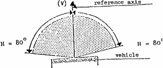
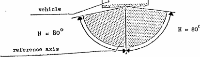
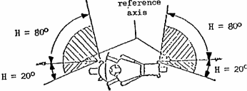
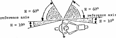
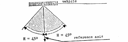
Annex 1 - Minimum horizontal (H) and minimum vertical (V) angles for spatial lamp distribution
Annex 2 - Communication concerning the approval (or refusal or withdrawal of approval or production definitely discontinued) of a type of device pursuant to Regulation No. 50
Annex 3 - Arrangement of the approval mark
Annex 4 - Photometric measurements
Annex 5 - Colours of lamps trichromatic co-ordinates
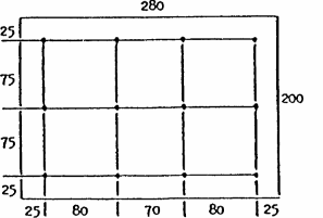
Annex 6 - Photometric measurements for the rear-registration-plate illuminating device
Annex 7 - Definition of the terms of paragraphs 2.7. to 2.11. of this Regulation
Regulation No. 50
UNIFORM PROVISIONS CONCERNING THE APPROVAL OF FRONT POSITION LAMPS, REAR POSITION LAMPS, STOP LAMPS, DIRECTION INDICATORS AND REAR-
REGISTRATION-PLATE ILLUMINATING DEVICES FOR MOPEDS, MOTOR CYCLES AND VEHICLES TREATED AS SUCH
1. SCOPE
This Regulation applies to the approval of front position lamps, rear position lamps, stop lamps, direction indicators, and rear-registration-plate illuminating devices intended to be fitted to mopeds, motor cycles and vehicles treated as such.
2. DEFINITIONS
For the purpose of this Regulation,
2.1. "lamp" means a device designed to illuminate the road or to emit a luminous signal; rear- registration-plate illuminating devices and reflex reflectors shall likewise be regarded as lamps;
2.1.1. "independent lamps" means lamps having separate lenses, separate light sources and separate lamp bodies;
2.1.2. "grouped lamps" means devices having separate lenses and separate light sources, but a common lamp body;
2.1.3. "combined" means devices having separate lenses but a common light source and a common lamp body;
2.1.4. "reciprocally incorporated" means devices having separate lights sources (or a single light source operating in different ways), totally or partial common lenses and a common lamp body;
2.2. "front position lamp" means the lamp used to indicate the presence of the vehicle when viewed from the front;
2.3. "rear position lamp" means the lamp used to indicate the presence of the vehicle when viewed from the rear;
2.4. "stop lamp" means the lamp used to indicate to other road users to the rear of the vehicle that the driver is applying the service brake;
2.5. "direction indicator lamp" means the lamp used to indicate to other road users that the driver intends to change direction to the right or to the left: (see also Annex 1);
2.5.1. "direction indicator lamp of the category 11" means a direction indicator lamp intended to be fitted to the front of the vehicle;
2.5.2. "direction indicator lamp of the category 12" means a direction indicator lamp intended to be fitted to the rear of the vehicle;
2.5.3. "direction indicator lamp of the category 31" means a direction indicator lamp intended to be fitted on the side of the vehicle,
2.6. "rear-registration-plate illuminating device" means the device used to illuminate the space reserved for the rear registration plate; such device may consist of various optical components (see also Annex 6);
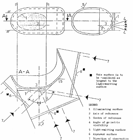
2.7. "illuminating surface" (see Annex 7);
2.7.1. "light-emitting surface" means all or part of the surface of the transparent material that encloses the lighting device and allows compliance with photometric and colorimetric characteristic standards;
2.7.2. "illuminating surface of a light-signalling device" means the orthogonal projection of the lamp on a plane perpendicular to its axis of reference and in contact with the transparent outer surface of the lamp such projection being bounded by the covering of the screen edges situated in that plane and each allowing only 98% of the total intensity of the lamp to subsist in the direction of the axis of reference; for the purposes of determining the lower, upper and lateral edges of the lamp, only screens having a horizontal or a vertical edge shall be considered;
2.8. "apparent surface" for a specific direction, means the orthogonal projection of the surface of the light-emitting surface on a plan perpendicular to the direction of observation;
2.9. "axis of reference" (or "reference axis") means the characteristic axis of the lamp signal determined by the manufacturer of the lamp for use as the direction of reference (H = 0, V = 0 degrees) for angles of field for photometric measurements and for installing the lamp on the vehicle;
2.10. "centre of reference" means the intersection of the axis of reference with the light emitting surface; it is specified by the manufacturer of the lamp;
2.11. "angles of geometric visibility" means the angles which determine the minimum solid- angle zone in which the apparent surface of the lamp must be visible; this solid-angle zone is defined by the segments of a sphere whose centre coincides with the centre of reference of the lamp and whose equator is parallel to the carriageway; the segments are determined from the axis of reference; the horizontal angles beta correspond to longitude, the vertical angles alpha to latitude; within the angles of geometric visibility there must obstacle to the propagation of light from any part of the apparent surface of the lamp; no account is taken of obstacles existing at the time of approval where required, of the lamp.
3. APPLICATION FOR APPROVAL
3.1. The application for approval shall be submitted by the holder of the trade name or mark or by his duly accredited representative. It shall specify:
3.1.1. the purpose or purposes for which the device submitted for approval is intended;
3.1.2. in the case of a front position lamp, whether it is intended to emit white or selective- yellow light;
3.1.3. in the case of a direction indicator: the category.
3.2. For each type of device, the application shall be accompanied by:
3.2.1. drawings, in triplicate, in sufficient detail to permit identification of the type of the device and showing in what geometrical position the device is to be mounted on the vehicle; the direction of observation to be taken as the axis of reference in the tests (horizontal angle H = 0, vertical angle V = 0); and the point to be taken as the centre of reference in the said tests; the drawings shall show the position intended for the approval mark and eventually the additional symbols in relation to the circle of the approval mark;
3.2.2. A brief technical description stating, in particular, with the exception of lamps with non- replaceable light sources, the category or categories of filament lamps prescribed; this filament lamp category shall be one of those contained in Regulation No. 37.
3.2.3. two devices.
4. MARKINGS
4.1. Devices submitted for approval shall in a clearly legible and indelible way bear the following markings:
4.1.1. the trade name or mark of the applicant,
4.1.2. The indication of the filament lamp category or categories provided; this is not valid for lamps with non-replaceable light sources.
4.2. They shall comprise furthermore a space of sufficient size for the approval mark. (See paragraph 3.2.1.).
4.3. In the case of lamps with non-replaceable light sources the rated voltage and rated wattage.
5. APPROVAL
5.1. If the two devices of a type of device which are submitted in pursuance of paragraph 3 above, meet the requirements of this Regulation, approval shall be granted.
5.2. When two or more lamps are part of the same device, approval is only granted, if each of these lamps satisfies the provisions of this Regulation or of another Regulation. Lamps not satisfying any one of those Regulations, shall not be part of such device.
5.3. An approval number shall be assigned to each type approved. Its first two digits (at present 00 for the Regulation in its original form) shall indicate the series of amendments incorporating the most recent major technical amendments to the Regulation at the time of issue of the approval. The same contracting Party may not assign the same number to another type of device covered by this Regulation.
5.4. Notice of approval or of refusal of approval of a type of device pursuant to this Regulation shall be communicated to the Parties to the Agreement applying this Regulation, by means of a form conforming to the model shown in Annex 2 to this Regulation and of an attached drawing supplied by the applicant for approval, in a format not exceeding A4 (210 x 297 mm) and, possible, on a scale of 1:1.
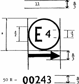
5.5. Each device conforming to a type approved under this Regulation shall bear, in the space referred to in paragraph 4.2. above, in addition to the markings referred to in paragraphs 4.1. and 4.3. an international approval mark consisting of:
5.5.1. a circle enclosing the letter "E" followed by the distinguishing number of the country which has granted the approval, and
5.5.2. the number of this Regulation, followed by the letter "R", a dash and the approval number;
5.5.3. in the general case of a direction indicator: a number indicating the category 11, 12 or 31 close to the circle according to paragraph 5.5.1. and on the opposite side to the approval number;
5.5.4. in the case of a direction indicator, which does on one side not attain the minimum luminous intensity prescribed up to an angle of H = 80 degrees according to paragraph 7.7.1.: a horizontal arrow, the tip of which is oriented to the side where the minimum luminous intensity according to paragraph 7.7.1. is complied with up to an angle of at least 80 degrees .
5.6. Where a device has been found to comply with the requirements of several Regulations, a single approval mark may be applied comprising a circle according to paragraph 5.5.1., the approval numbers, and the additional symbols appropriate to each Regulation under which approval has been granted. The size of the components of this single approval mark shall not be less than the minimum size required for the smallest of the individual marks under a Regulation, under which approval has been granted.
5.7. The marks referred to in paragraph 5.5. above shall be indelible and clearly legible; furthermore, the trade name or mark and the approval mark(s) shall be clearly legible, even when the device is fitted to the vehicle.
5.8. Annex 3 gives an example of arrangement of the approval mark.
6. GENERAL SPECIFICATIONS
6.1. Each device shall conform to the specifications of this Regulation.
6.2. The devices must be so designed and constructed that in normal use, and despite the vibrations to which they may be subjected, their satisfactory operation continues to be assured and they retain the characteristics prescribed by this Regulation.
7. INTENSITY OF LIGHT EMITTED
In the reference axis, the intensity of the emitted light of each of the two devices shall be at least equal to the minimum values and not exceed the maximum values of the following table. In no direction, the maximum values indicated shall be exceeded.
7.1. Rear position lamp
min. (cd) 4
max. (cd) 12
7.2. Front position lamp
min. (cd) 4
max. (cd) 60
7.3. Stop lamp
min. (cd) 40
max. (cd) 100
7.4. Direction indicators
7.4.1. of the category 11 (see Annex 1)
min. (cd) 90
max. (cd) 700 3/
7.4.2. of the category 12 (see Annex 1)
min. (cd) 50
max. (cd) 200
7.4.3. of the category 31 (see Annex 1) to the front
min. (cd) 90
max. (cd) 700 to the rear
min. (cd) 50
max. (cd) 200
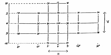
7.5. Outside of the reference axis and within the angle fields defined in the diagrams in Annex 1 to this Regulation, the intensity of the light emitted shall, in each direction corresponding to the points in the light distribution table reproduced in Annex 4 to this Regulation, be not less than the product of the minima specified in paragraph 7.1. to 7.4. above and of the percentage specified in the said table for the direction in question.
7.6. As an exception to paragraph 7.1. above, a luminous intensity of 60 cd maximum shall be permitted for rear position lamps reciprocally incorporated with stop lamps, below a plane forming an angle of 5 degrees with and downward from a horizontal plane.
7.7. Moreover,
7.7.1. throughout the fields defined in Annex 1, the intensity of the light emitted shall be not less than 0.05 cd for position lamps and not less than 0.3 cd for stop lamps and direction indicators;
7.7.2. if a position lamp is grouped or reciprocally incorporated with a stop lamp, the ratio between the luminous intensities actually measured of the two lamps when turned on simultaneously and the intensity of the rear position lamp when turned on alone shall be at least 5:1 to the eleven measuring points defined in Annex 4 and situated in the field delimited by straight vertical lines passing through 0 degrees V/+/- 10 degrees H and the straight horizontal lines passing through +/- 5 degrees V/0 degrees H of the light distribution table;
7.7.3. the provisions of paragraph 2.2. of Annex 4 to this Regulation on local variations of intensity shall be observed.
7.8. The luminous intensities shall be measured with the filament lamp continuously alight. In the case of lamps working intermittently, precaution shall be taken to avoid overheating of the device.
7.9. Annex 4, to which reference is made in paragraph 7.5. above, gives particulars of the methods of measurement to be used.
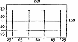
7.10. The rear-registration-plate illuminating device shall comply with the specifications indicated in Annex 6 to this Regulation.
7.11. The photometric performance lamps equipped with several light sources shall be checked in accordance with the provisions of Annex 4.
8. TEST PROCEDURE
8.1. All measurements shall be carried out with an uncoloured standard filament lamp of the category prescribed for the advice, adjusted to produce the reference luminous flux prescribed for the filament lamp involved (see Regulation No. 37).
"All measurements on lamp with non-replaceable light sources shall be made at 6.75 V and 13.5 V respectively."
8.2. The vertical and horizontal outlines of the illuminating surface of a light-signalling device (paragraph 2.7.2.) shall be determined and measured in relation to the centre of reference (paragraph 2.10).
9. COLOUR OF LIGHT EMITTED
Stop lamps and rear position lamps shall emit red light, front position lamps may emit white or selective-yellow light, direction indicators shall emit amber light.
The colour of the light emitted, measured using a light source having a colour temperature of 2856 K, shall be within the limits of the co-ordinates prescribed for the colour in question in Annex 5 to this Regulation.
However, for lamps equipped with non-replaceable light sources, the colorimetric characteristics should be verified with the light sources present in the lamps at a voltage of 6.75 V, 13.5 V or 28.0 V.
10. CONFORMITY OF PRODUCTION
Every device bearing an approval mark as prescribed under this Regulation shall conform to the type approved and shall comply with the requirements of this Regulation. However, in the case of a device picked at random from series production, the requirements as to the respectively minimum and maximum intensities of the light emitted (measured with a standard filament lamp as referred to in paragraph 8 above) shall be at least 80% of the minimum values specified and not exceed 120% of the maximum values allowed.
11. PENALTIES FOR NON-CONFORMITY OF PRODUCTION
11.1 The approval granted in respect of a device pursuant to this Regulation may be withdrawn if the foregoing conditions are not observed.
11.2 If a Contracting Party to the Agreement, applying this Regulation, withdraws an approval it has previously granted, it shall forthwith so notify the other Contracting Parties applying this Regulation, by means of a copy of the approval form bearing at the end, in large letters, the signed and dated annotation "APPROVAL WITHDRAWN".
12. PRODUCTION DEFINITELY DISCONTINUED
If the holder of the approval completely ceases to manufacture a device approved in accordance with this Regulation, he shall so inform the authority which granted the approval. Upon receiving the relevant communication, that authority shall inform thereof the other Parties to the Agreement which apply this Regulation by means of a copy of the approval form bearing at the end, in large letters, the signed and date annotation "PRODUCTION DISCONTINUED".
13. NAMES AND ADDRESSES OF TECHNICAL SERVICES RESPONSIBLE FOR CONDUCTING APPROVAL TESTS, AND OF ADMINISTRATIVE DEPARTMENTS
The Parties to the Agreement which apply this Regulation shall communicate to the United Nations Secretariat the names and addresses of the technical services responsible for conducting approval tests and of the administrative departments which grant approval and to which forms certifying approval or refusal or withdrawal of approval issued in other countries, are to be sent.