Manual of Standards Part 139—Aerodromes

Version 1.8: February 2012


Made under Part 139 of the Civil Aviation Safety Regulations 1998.

This compilation was prepared on 4 February 2012 taking into account amendments up to Manual of Standards Part 139 Amendment 2012 (No. 1).

Prepared by the Airways and Aerodromes Branch, Airspace and Aerodrome Regulation Division, Civil Aviation Safety Authority, Canberra.


Manual of Standards Part 139—Aerodromes

© Copyright Australian Government 2012

This work is copyright.  Apart from any use as permitted under the Copyright Act 1968, no part may be reproduced by any process without prior written permission from the Commonwealth.  Requests and inquiries concerning reproduction and rights should be addressed to the Document Control Officer, Infrastructure and Information Management Branch, Civil Aviation Safety Authority, GPO Box 2005, Canberra ACT 2601 or posted to document.control.unit@casa.gov.au.

You should always refer to the applicable provisions of the Civil Aviation Act, Civil Aviation Regulations and Civil Aviation Orders, rather than this manual, to ascertain the requirements of, and the obligations imposed by or under, the civil aviation legislation.

Version 1.8: February 2012

Table of Contents


Table of Contents

Chapter 1: Introduction

Section 1.1: General

1.1.1 Commencement and Background

1.1.2 Document Set

1.1.3 Differences Between ICAO Standards and those in MOS

1.1.4 Differences published in AIP

1.1.5 MOS Documentation Change Management

1.1.6 Related Documents

Section 1.2: Definitions

Chapter 2: Application of Standards to Aerodromes

Section 2.1: General

2.1.1 Legislative Background and Applicability

2.1.2 Standard Changes and Existing Aerodrome Facilities

2.1.3 Exemptions to Standards

2.1.4 Conflict with Other Standards

2.1.5 Using ICAO Aerodrome Reference Code to Specify Standards

2.1.6 Aerodrome Reference Codes and Aeroplane Characteristics

2.1.7 Providing for Future Larger Aeroplanes

2.1.8 Non-instrument and Instrument Runways

2.1.9 Non-precision Approach Runways

Chapter 3: Applying for an Aerodrome Certificate

Section 3.1: General

3.1.1 Introduction

3.1.2 Aerodrome Certificate Processing Fee

3.1.3 Processing an Aerodrome Certificate Application

3.1.4 Granting of an Aerodrome Certificate

3.1.5 Maintenance and Control of Aerodrome Manual

3.1.6 Initiating NOTAM to Promulgate a Certified Aerodrome

3.1.7 Transitional Arrangements for Existing Aerodrome Licences

Section 3.2: Application for an Aerodrome Certificate

3.2.1 Sample Aerodrome Certificate Application

Chapter 4: Applying to Register an Aerodrome

Section 4.1: General

4.1.1 Introduction

4.1.2 Aerodrome Registration Application and Processing Fee

4.1.3 Approving a Registration Application

4.1.4 Maintenance of Registration

4.1.5 Aerodrome Safety Inspection Report

Section 4.2: Application to Register an Aerodrome

4.2.1 Application to Register an Aerodrome

Chapter 5: Aerodrome Information for AIP

Section 5.1: General

5.1.1 Introduction

5.1.2 Aerodrome Information to be Provided for a Certified Aerodrome

5.1.3 Standards for Determining Aerodrome Information

5.1.4 Obstacle Data

Section 5.2: Illustration of Declared Distances

5.2.1 Introduction

5.2.2 Calculation of Declared Distances

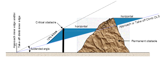
5.2.3 Obstacle-free Take-off Gradient

5.2.4 Critical Obstacle

5.2.5 Declared Distances for Intersection Departures

Section 5.3: Illustration of Supplementary Take-Off Distances Available and Shielding

5.3.1 Introduction

Chapter 6: Physical Characteristics

Section 6.1: General

6.1.1 Introduction

Section 6.2: Runways

6.2.1 Location of Runway Threshold

6.2.2 Length of Runway

6.2.3 Runway Width

6.2.4 Runway Turning Area

6.2.5 Parallel Runways

6.2.6 Runway Longitudinal Slope

6.2.7 Runway Sight Distance

6.2.8 Transverse Slopes on Runways

6.2.9 Runway Surface

6.2.10 Runway Bearing Strength

6.2.11 Runway Shoulders

6.2.12 Characteristics of Runway Shoulders

6.2.13 Transverse Slope on Runway Shoulder

6.2.14 Surface of Runway Shoulder

6.2.15 Provision of Runway Strip

6.2.16 Composition of Runway Strip

6.2.17 Runway Strip Length

6.2.18 Runway Strip Width

6.2.19 Longitudinal Slope on Graded Area of Runway Strip

6.2.20 Longitudinal Slope Changes on Graded Area of Runway Strip

6.2.21 Runway Strip Longitudinal Slope Changes at Runway Ends (Radio Altimeter Operating Area)

6.2.22 Runway Strip Transverse Slope

6.2.23 Surface of Graded Area of Runway Strip

6.2.24 Objects on Runway Strips

6.2.25 Runway End Safety Area (RESA)

6.2.26 Dimensions of RESA

6.2.27 Slopes on RESA

6.2.28 Objects on RESA

6.2.29 Bearing Strength of RESA

6.2.30 Clearways

6.2.31 Location of Clearways

6.2.32 Dimensions of Clearways

6.2.33 Slopes on Clearways

6.2.34 Objects on Clearways

6.2.35 Stopways

6.2.36 Dimensions of Stopways

6.2.37 Surface of Stopway

6.2.38 Stopway Slopes and Slope Changes

6.2.39 Bearing Strength of Stopway

Section 6.3: Taxiways

6.3.1 Taxiway Width

6.3.2 Taxiway Edge Clearance

6.3.3 Taxiway Curves

6.3.4 Taxiway Longitudinal Slope

6.3.5 Taxiway Transverse Slope

6.3.6 Taxiway Sight Distance

6.3.7 Taxiway Bearing Strength

6.3.8 Taxiway Shoulders

6.3.9 Width of Taxiway Shoulders

6.3.10 Surface of Taxiway Shoulders

6.3.11 Taxiway Strips

6.3.12 Width of Taxiway Strip

6.3.13 Width of Graded Area of Taxiway Strip

6.3.14 Slope of Taxiway Strip

6.3.15 Objects on Taxiway Strip

6.3.16 Taxiways on Bridges

6.3.17 Taxiway Minimum Separation Distances

Section 6.4: Holding Bays, Runway-Holding Positions, Intermediate Holding Positions and Road-Holding Positions

6.4.1 Introduction

6.4.2 Provision of a Holding Bay, Runway-holding Position, Intermediate Holding Position and Road-holding Position

6.4.3 Location of Holding Bay, Runway-holding Position, Intermediate Holding Position or Road-holding Position

6.4.4 Distance from Runway-holding Position, Intermediate Holding Position or Road-holding Position to Runway Centreline

Section 6.5: Aprons

6.5.1 Location of Apron

6.5.2 Separation Distances on Aprons

6.5.3 Slopes on Aprons

6.5.4 Apron Bearing Strength

6.5.5 Apron Road

Section 6.6: Jet Blast

6.6.1 General

6.6.2 Jet Blast and Propeller Wash Hazards

Section 6.7: Glider Facilities

6.7.1 Location of Glider Runway Strips

6.7.2 Dimensions of Glider Runway Strips

6.7.3 Glider Parking Areas

6.7.4 Glider Runway Strip Serviceability

6.7.5 Glider Runway Strip Standards

6.7.6 Notification of Glider Facilities and Procedures

Chapter 7: Obstacle Restriction and Limitation

Section 7.1: General

7.1.1 Introduction

7.1.2 Obstacle Restriction

7.1.3 Obstacle Limitation

7.1.4 Procedures for Aerodrome Operators to Deal with Obstacles

7.1.5 Objects Outside the OLS

7.1.6 Objects That Could Become Obstacles

7.1.7 Monitoring of Obstacles Associated with Instrument Runways

7.1.8 Additional Obstacle Assessment for an Existing Non-instrument Runway to be Upgraded to a Non-precision Instrument Runway

7.1.9 Obstacle Protection for Curved Take-Off

Section 7.2: Aerodrome Obstacle Charts

7.2.1 Type A Charts

7.2.2 Type B Charts

7.2.3 Type C Charts

7.2.4 Precision Approach Terrain Charts – ICAO

Section 7.3: Obstacle Limitation Surfaces

7.3.1 General

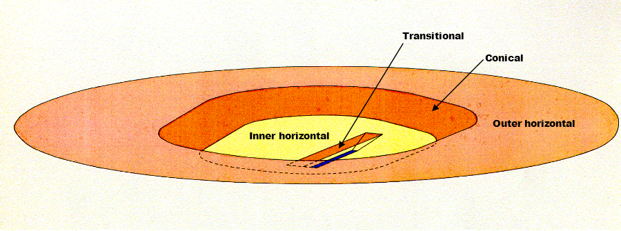
7.3.2 Description of OLS

Section 7.4: Principles of Shielding

7.4.1 General

7.4.2 Shielding Principles

Chapter 8: Visual Aids Provided by Aerodrome Markings, Markers, Signals and Signs

Section 8.1: General

8.1.1 Introduction

8.1.2 Closed Aerodrome

8.1.3 Colours

8.1.4 Visibility

Section 8.2: Markers

8.2.1 Introduction

8.2.2 The Use of Markers on a Runway Strip

8.2.3 The Use of Markers on an Unsealed Runway

8.2.4 The Use of Markers on an Unsealed Taxiway

8.2.5 The Use of Markers on an Unsealed Apron

Section 8.3: Runway Markings

8.3.1 General

8.3.2 Pre-runway-end Markings

8.3.3 Runway Centreline Markings

8.3.4 Runway Designation Markings

8.3.5 Runway End Markings

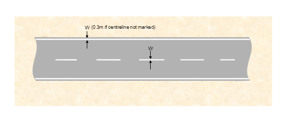
8.3.6 Runway Side-stripe Markings

8.3.7 Aiming Point Markings

8.3.7A Touchdown Zone Marking

8.3.8 Runway Threshold Markings

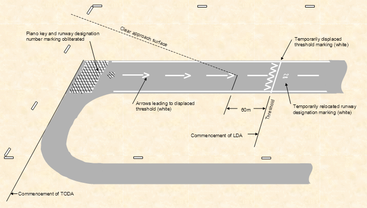
8.3.9 Temporarily Displaced Threshold Markings

8.3.10 Runway Land and Hold Short Position Markings

Section 8.4: Taxiway Markings

8.4.1 Introduction

8.4.2 Taxi Guideline Markings

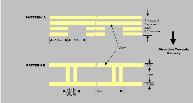
8.4.3 Runway Holding Position Markings

8.4.4 Intermediate Holding Position Markings

8.4.5 Taxiway Edge Markings

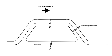
8.4.6 Holding Bay Markings

8.4.7 Taxiway Pavement Strength Limit Markings

Section 8.5: Apron Markings

8.5.1 Introduction

8.5.2 Apron Taxi Guideline Markings

8.5.3 Apron Edge Markings

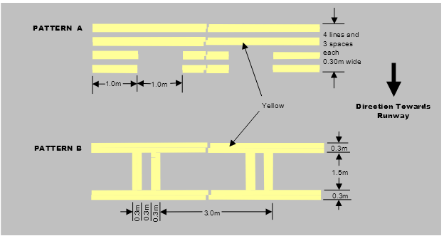
8.5.4 Parking Clearance Line

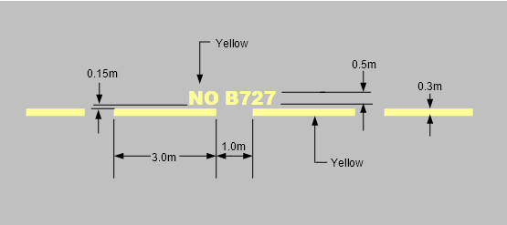
8.5.5 Aircraft Type Limit Line

8.5.6 Parking Weight Limit Line

8.5.7 Leased Area Line

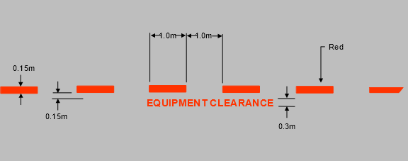
8.5.8 Equipment Clearance Line

8.5.9 Equipment Storage Markings

8.5.10 Apron Service Road Markings

8.5.11 Aircraft Parking Position Markings
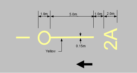
8.5.12 Lead-in Line

8.5.13 Taxi Lead-in Line Designation

8.5.14 Pilot Turn Line

8.5.15 Primary Aircraft Parking Position Markings

8.5.16 Marshaller Stop Line

8.5.17 Pilot Stop Line

8.5.18 Alignment Line

8.5.19 Secondary Aircraft Parking Position Markings

8.5.20 Keyhole Marking

8.5.21 Triangle Marking

8.5.22 Lead-out Line

8.5.23 Designation Markings

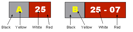
8.5.24 Aircraft Parking Position Designation

8.5.25 Designation Characters for Taxi and Apron Markings

8.5.26 Tug operator Guidance Marking

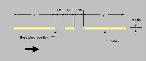
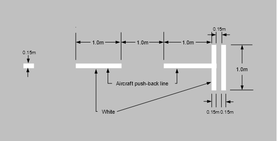
8.5.27 Aircraft Push-back Lines

8.5.28 Tug Parking Position Lines

8.5.29 Towbar Disconnect Markings

8.5.30 Push-back Limit Markings

8.5.31 Push-back Alignment Bars

8.5.32 Passenger Path Markings

8.5.33 Typical Apron Markings

Section 8.6: Movement Area Guidance Signs (MAGS)

8.6.1 Introduction

8.6.2 Naming of taxiways

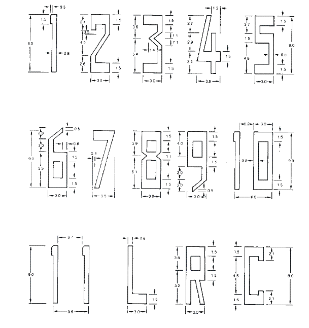
8.6.3 Dimensions, Location and Lettering

8.6.4 Sign Size and Location Distances, Including Runway Exit Signs

8.6.5 Structural

8.6.6 Illumination

8.6.7 MAGS with Mandatory Instructions

8.6.8 Runway Designation Signs

8.6.9 Category I, II or III Runway Designation Signs

8.6.10 Runway Holding Position Sign

8.6.11 Aircraft NO ENTRY Sign

8.6.12 Vehicular STOP Signs

8.6.13 Runway/Runway Intersection Signs

8.6.14 MAGS with Information

8.6.15 Taxiway Location Signs

8.6.16 Direction Signs

8.6.17 Destination Signs

8.6.18 Take-off Run Available Sign

8.6.19 Runway Exit Signs

8.6.20 LAHSO Distance To Go Signs

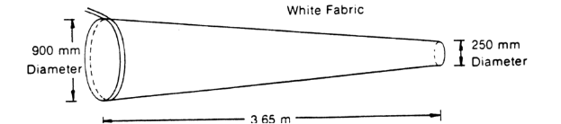
Section 8.7: Wind Direction Indicators

8.7.1 Requirements

8.7.2 Standards

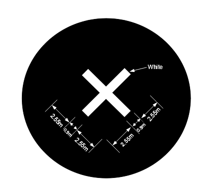
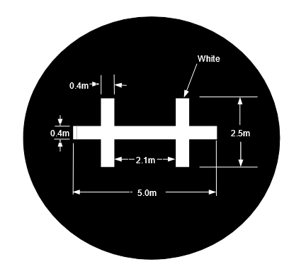
Section 8.8: Ground Signals

8.8.1 Signal Areas

8.8.2 Ground Signals in Signal Area

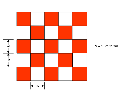
Section 8.9: Marking of Unserviceable and Work Areas

8.9.1 Introduction

8.9.2 Marking of Unserviceable Areas on Runways, Taxiways and Aprons

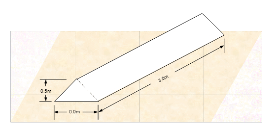
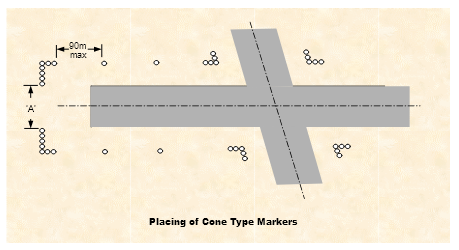
8.9.3 Use of Unserviceability Markers

8.9.4 Works Limit Markers

Section 8.10: Obstacle Markings

8.10.1 General

8.10.2 Marking of Obstacles

8.10.3 Marking of Temporary and Transient Obstacles

8.10.4 Marking of Vehicles

Section 8.11: Helicopter Areas on Aerodromes

8.11.1 Introduction

8.11.2 Helicopter Landing and Lift-off Area Markings

8.11.3 Helicopter Apron Markings

8.11.4 Helicopter Parking Position Markings

8.11.5 Helicopter Taxi Guideline Designation

8.11.6 Helicopter Parking Position Numbers

8.11.7 Helicopter Apron Edge Markings

Section 8.12: Marking of Glider Runway Strips on an Aerodrome

Chapter 9: Visual Aids Provided by Aerodrome Lighting......................9-1

Section 9.1: General.....................................................9-1

9.1.1 Application and Definitions.......................................9-1

9.1.2 Standardisation of Aerodrome Lighting.............................9-4

9.1.3 Lighting in the Vicinity of an Aerodrome............................9-5

9.1.4 Minimum Lighting System Requirements...........................9-5

9.1.5 Primary Source of Electricity Supply...............................9-6

9.1.6 Electrical Circuitry...............................................9-6

9.1.7 Secondary Power Supply........................................9-7

9.1.8 Switch-over Time...............................................9-8

9.1.9 Standby Power Supply..........................................9-9

9.1.10 Portable Lighting................................................9-9

9.1.11 Light Fixtures and Supporting Structures..........................9-11

9.1.12 Elevated and Inset Lights.......................................9-12

9.1.13 Colour of Light Shown..........................................9-12

9.1.14 Light intensity and Control......................................9-13

9.1.15 Commissioning of Lighting Systems..............................9-17

Section 9.2: Colours for Aeronautical Ground Lights.....................9-20

9.2.1 General......................................................9-20

9.2.2 Chromaticities.................................................9-20

9.2.3 Discrimination Between Coloured Lights..........................9-21

Section 9.3: Pilot Activated Lighting Systems............................9-23

9.3.1 General......................................................9-23

9.3.2 VHF Carrier Activation Code....................................9-24

9.3.3 VHF Carrier Detector Technical Requirements.....................9-25

9.3.4 Inputs to the PAL..............................................9-25

9.3.5 Fail-safe Arrangements with PAL system.........................9-26

9.3.6 Access to Manual Switches.....................................9-26

9.3.7 Receiving Antenna.............................................9-27

9.3.8 PAL with Audio Acknowledgment................................9-27

Section 9.4: Obstacle Lighting..........................................9-28

9.4.1 General......................................................9-28

9.4.2 Types of Obstacle Lighting and Their Use.........................9-29

9.4.3 Location of Obstacle Lights.....................................9-29

9.4.4 Natural Obstacles..............................................9-35

9.4.5 Temporary Obstacles..........................................9-35

9.4.6 Characteristics of Low Intensity Obstacle Lights....................9-35

9.4.7 Characteristics of Medium Intensity Obstacle Lights................9-36

9.4.8 Characteristics of High Intensity Obstacle Lights...................9-36

9.4.9 Floodlighting of Obstacles......................................9-38

9.4.10 Ongoing Availability of Obstacle Lights...........................9-38

Section 9.5: Aerodrome Beacons........................................9-40

9.5.1 General......................................................9-40

Section 9.6: Illuminated Wind Direction Indicator.........................9-42

9.6.1 General......................................................9-42

Section 9.7: Approach Lighting Systems.................................9-44

9.7.1 Simple Approach Lighting System...............................9-44

9.7.2 Precision Approach Category I Lighting System....................9-44

9.7.3 Precision Approach Categories II and III Lighting System...........9-48

Section 9.8: Isocandela Diagrams of Approach Lighting..................9-52

9.8.1 Collective Notes...............................................9-52

Section 9.9: Visual Approach Slope Indicator Systems....................9-54

9.9.1 General......................................................9-54

9.9.2 Obstacle Assessment Surface...................................9-55

9.9.3 T-VASIS and AT-VASIS........................................9-57

9.9.4 Precision Approach Path Indicator (PAPI) system..................9-62

Section 9.10: Runway Lighting..........................................9-70

9.10.1 Types of Runway Edge Lighting Systems.........................9-70

9.10.2 Runway Edge Lights...........................................9-70

9.10.3 Location of Runway Edge Lights.................................9-71

9.10.4 Longitudinal Spacing of Runway Edge Lights......................9-71

9.10.5 Lateral Spacing of Runway Edge Lights...........................9-72

9.10.6 Characteristics of Low and Medium Intensity Runway Edge Lights...9-72

9.10.7 Characteristics of High Intensity Runway Edge Lights...............9-72

9.10.8 Use of Bidirectional or Back-to-back Light Fittings..................9-73

9.10.9 Runway Threshold Lights.......................................9-73

9.10.10 Location of Runway Threshold Lights.............................9-73

9.10.11 Pattern of Low Intensity and Medium Intensity Runway Threshold Lights9-73

9.10.12 Pattern of High Intensity Runway Threshold Lights.................9-74

9.10.13 Characteristics of Low Intensity and Medium Intensity Runway Threshold Lights              9-74

9.10.14 Characteristics of High Intensity Runway Threshold Lights..........9-75

9.10.15 Additional Lighting to Enhance Threshold Location.................9-75

9.10.16 Runway End Lights............................................9-78

9.10.17 Location of Runway End Lights..................................9-78

9.10.18 Pattern of Runway End Lights...................................9-78

9.10.19 Characteristics of Low and Medium Intensity Runway End Lights.....9-79

9.10.20 Characteristics of High Intensity Runway End Lights................9-79

9.10.21 Runway Turning Area Edge Lights...............................9-79

9.10.22 Stopway Lights................................................9-80

9.10.23 Hold Short Lights..............................................9-80

9.10.24 Runway Centreline Lights.......................................9-81

9.10.25 Runway Touchdown Zone Lights................................9-82

9.10.26 Photometric Characteristics of Runway Lights.....................9-82

9.10.27 Installation and Aiming of Light Fittings...........................9-83

9.10.28 Illustrations of Runway Lighting..................................9-83

Section 9.11: Isocandela Diagrams of Runway Lighting...................9-84

9.11.1 Collective Notes...............................................9-84

Section 9.12: Illustrations of Runway Lighting............................9-96

Section 9.13: Taxiway Lighting.........................................9-103

9.13.1 Provision of Taxiway Centreline Lights...........................9-103

9.13.2 Provision of Taxiway Edge Lights...............................9-103

9.13.3 Taxiway Markers.............................................9-103

9.13.4 Apron Taxiway Lighting........................................9-104

9.13.5 Use of Different Types of Taxiway Lights.........................9-104

9.13.6 Control of Lights on Taxiways..................................9-104

9.13.7 Location of Taxiway Centreline Lights...........................9-105

9.13.8 Spacing of Taxiway Centreline Lights............................9-105

9.13.9 Location of Taxiway Centreline Lights on Exit Taxiways............9-106

9.13.10 Location of Taxiway Centreline Lights on Rapid Exit Taxiways......9-106

9.13.11 Characteristics of Taxiway Centreline Lights......................9-107

9.13.12 Beam Dimensions and Light Distribution of Taxiway Centreline Lights9-107

9.13.13 Location of Taxiway Edge Lights................................9-108

9.13.14 Spacing of Taxiway Edge Lights................................9-109

9.13.15 Characteristics of Taxiway Edge Lights..........................9-110

9.13.16 Provision of Runway Guard Lights..............................9-110

9.13.17 Pattern and Location of Runway Guard Lights....................9-111

9.13.18 Characteristics of Runway Guard Lights.........................9-112

9.13.19 Control of Runway Guard Lights................................9-113

9.13.20 Provision of Intermediate Holding Position Lights.................9-113

9.13.21 Pattern and Location of Intermediate Holding Position Lights.......9-113

9.13.22 Characteristics of Intermediate Holding Position Lights............9-114

9.13.23 Stop Bars....................................................9-114

9.13.24 Location of Stop Bars.........................................9-115

9.13.25 Characteristics of Stop Bars....................................9-115

9.13.26 Taxiway Edge Markers........................................9-115

9.13.27 Characteristics of Taxiway Edge Markers........................9-116

9.13.28 Taxiway Centreline Markers....................................9-116

9.13.29 Characteristics of Taxiway Centreline Markers....................9-116

9.13.30 Photometric Characteristics of Taxiway Lights....................9-116

9.13.31 Installation and Aiming of Light Fittings..........................9-117

Section 9.14: Isocandela Diagrams for Taxiway Lights...................9-118

9.14.1 Collective Notes to Figures....................................9-118

Section 9.15: Illustrations of Taxiway Lighting..........................9-125

Section 9.16: Apron Floodlighting......................................9-128

9.16.1 Introduction..................................................9-128

9.16.2 Provision of Apron Floodlighting................................9-128

9.16.3 Location of Apron Floodlighting.................................9-128

9.16.4 Characteristics of Apron Floodlighting...........................9-129

Section 9.17: Visual Docking Guidance Systems........................9-131

9.17.1 Provision of Visual Docking Guidance Systems...................9-131

9.17.2 Characteristics of Visual Docking Guidance Systems..............9-131

9.17.3 Azimuth Guidance Unit - Location...............................9-132

9.17.4 Azimuth Guidance Unit - Characteristics.........................9-132

9.17.5 Stopping Position Indicator - Location...........................9-132

9.17.6 Stopping Position Indicator - Characteristics......................9-132

9.17.7 Parking Position Identification Sign..............................9-133

9.17.8 Notification of Type of Aircraft Docking Guidance Systems.........9-133

Section 9.18: Lighting Associated with Closed and Unserviceable Areas..9-134

9.18.1 Closed Runway or Taxiway....................................9-134

9.18.2 Unserviceable Areas..........................................9-134

9.18.3 Characteristics of Unserviceability Lights.........................9-134

Section 9.19: Other Lights on an Aerodrome............................9-135

9.19.1 Vehicle Warning Lights........................................9-135

9.19.2 Works Limit Lights............................................9-135

9.19.3 Road and Car Park Lighting....................................9-135

9.19.4 Road-holding Position Light....................................9-135

Section 9.20: Monitoring, Maintenance and Serviceability of Aerodrome Lighting              9-137

9.20.1 General.....................................................9-137

9.20.2 Reporting of Aerodrome Lighting Outage........................9-137

Section 9.21: Lighting in the Vicinity of Aerodromes.....................9-141

9.21.1 Advice to Lighting Designers...................................9-141

9.21.1A Purpose of the Section........................................9-141

9.21.2 Legislative Background........................................9-141

9.21.3 General Requirement.........................................9-142

9.21.4 Light Fittings.................................................9-142

9.21.5 Coloured Lights..............................................9-143

9.21.6 Information and Correspondence...............................9-143

Section 9.22: Use of Unarmoured Cables for Aerodrome Lighting........9-145

9.22.1 Introduction..................................................9-145

9.22.2 Significant Areas of the Dispensation............................9-145

9.22.3 Conditions Governing the Dispensation..........................9-145

9.22.4 Aspects to Note..............................................9-146

9.22.5 Acceptability of an Installation to the Supply Authority.............9-146

Chapter 10: Operating Standards for Certified Aerodromes..................10-1

Section 10.1: General...................................................10-1

10.1.1 Introduction...................................................10-1

10.1.2 Aerodrome Manual and Aerodrome Operating Procedures..........10-1

10.1.3 Training of Aerodrome Personnel Involved with Safety Functions.....10-1

10.1.4 Aerodrome Safety Management System (SMS)....................10-2

Section 10.2: Inspecting and Reporting Aerodrome Serviceability.........10-3

10.2.1 General......................................................10-3

10.2.2 Significant Objects.............................................10-3

10.2.3 Surface Conditions of the Movement Area, Including the Presence of Water              10-4

10.2.4 Aerodrome Markings, Lightings, Wind Direction Indicators and Ground Signals              10-4

10.2.5 Cleanliness of the Movement Area...............................10-4

10.2.6 Obstacles Infringing the Take-off, Approach and Transitional Surfaces 10-5

10.2.7 Birds or Animals on, or in the Vicinity of, the Movement Area........10-5

10.2.8 Empirical Assessment of the Bearing Strength of Unrated Runway Pavements and Runway Strips              10-5

10.2.9 Currency of NOTAMs..........................................10-6

10.2.10 Aerodrome Fencing............................................10-6

10.2.11 Aerodrome Frequency Response Unit............................10-6

10.2.12 Inspection Logbooks...........................................10-6

Section 10.3: Initiating a NOTAM........................................10-7

10.3.1 Introduction...................................................10-7

10.3.2 Changes Reported to Australian NOTAM Office....................10-7

10.3.3 Time-Limited NOTAM..........................................10-8

10.3.4 Permanent NOTAM............................................10-8

10.3.5 Making Changes to Aerodrome Information Published in AIP-ERSA..10-9

10.3.6 Bird or Animal Hazard Warning..................................10-9

10.3.7 New or Upgraded Visual Aids...................................10-9

10.3.8 Changes to Type A Chart Information............................10-9

10.3.9 Follow up Actions..............................................10-9

10.3.10 Record Keeping...............................................10-9

Section 10.4: Sample Aerodrome Report Form..........................10-10

Section 10.5: Examples of NOTAM and Listing of Abbreviations..........10-11

10.5.1 Examples....................................................10-11

10.5.2 General Word Abbreviations and Phrase Contractions to Minimise Message Length of Aerodrome NOTAMs              10-14

Section 10.6: Appointment of Reporting Officers........................10-31

10.6.1 General.....................................................10-31

10.6.2 Reporting Officer Qualifications.................................10-31

10.6.3 What to Report...............................................10-31

10.6.4 Monitoring Activities Outside Aerodrome.........................10-32

Section 10.7: Aerodrome Emergency Planning..........................10-33

10.7.1 Introduction..................................................10-33

10.7.2 Records.....................................................10-34

10.7.3 Disabled Aircraft Removal.....................................10-34

Section 10.8: Guidelines for Aerodrome Emergency Plans...............10-35

10.8.1 General.....................................................10-35

10.8.2 Medical Subcommittee........................................10-36

10.8.3 Testing Facilities and Reviewing Roles..........................10-36

10.8.4 Aerodrome Emergency Exercises...............................10-36

10.8.5 Emergency Operations Centre and Mobile Command Post.........10-37

10.8.6 Definitions of Command, Control, and Coordination...............10-37

10.8.7 Role of the Police.............................................10-38

Section 10.9: Control of Airside Access Including Vehicle Control........10-39

10.9.1 Introduction..................................................10-39

10.9.2 Airside Vehicle Control........................................10-39

10.9.3 Airside drivers................................................10-39

10.9.4 Technical Standards for Electronic Surveillance Equipment Fitted to Vehicles              10-40

Section 10.10: Aerodrome Works Safety................................10-42

10.10.1 Introduction..................................................10-42

10.10.2 Method of Working Plans......................................10-42

10.10.3 Time-Limited Works...........................................10-43

10.10.4 Restrictions on Carrying Out Time-Limited Works.................10-43

10.10.5 Restoration of Normal Safety Standards.........................10-44

10.10.6 Resumption of Aerodrome Works...............................10-44

10.10.7 Management and Control of Aerodrome Works...................10-44

10.10.8 Markers, Markings and Lights..................................10-45

10.10.9 Communication Equipment....................................10-45

10.10.10 Completion..................................................10-45

10.10.11 Pavement Overlay Works......................................10-46

10.10.12 Works on Runway Strips......................................10-46

Section 10.11: Method of Working Plans................................10-48

10.11.1 Introduction..................................................10-48

10.11.2 Title Page...................................................10-48

10.11.3 Works Information............................................10-48

10.11.4 Restrictions to Aircraft Operations and Issue of NOTAMs..........10-49

10.11.5 Work Stages.................................................10-49

10.11.6 Emergencies and Adverse Weather.............................10-49

10.11.7 NOTAMs....................................................10-49

10.11.8 Restrictions to Works Organisations.............................10-49

10.11.9 Personnel and Equipment.....................................10-49

10.11.10 Access......................................................10-49

10.11.11 Aerodrome Markers, Markings and Lights........................10-50

10.11.12 Protection of Electrical Services................................10-50

10.11.13 Special Requirements.........................................10-50

10.11.14 Administration................................................10-50

10.11.15 Authority....................................................10-50

10.11.16 Drawings....................................................10-50

10.11.17 Distribution List...............................................10-51

Section 10.12: Functions of a Works Safety Officer......................10-52

10.12.1 Works Safety Officer..........................................10-52

Section 10.13: Aircraft Parking.........................................10-54

10.13.1 Introduction..................................................10-54

10.13.2 Apron Congestion............................................10-54

10.13.3 Apron Safety Management.....................................10-54

Section 10.14: Bird and Animal Hazard Management.....................10-55

10.14.1 Introduction..................................................10-55

Section 10.15: Pavement Maintenance..................................10-56

10.15.1 Pavement Cleanliness........................................10-56

10.15.2 Runway Surface Friction.......................................10-56

10.15.3 Deterioration of Runway Grooves...............................10-57

10.15.4 Surface Irregularities..........................................10-58

10.15.5 Standards for Natural and Gravel Surface Runways...............10-58

Section 10.16: Maintenance Around Navigational Aids...................10-59

10.16.1 Introduction..................................................10-59

Section 10.17: Aerodrome Safety Procedures during Conditions of Reduced Visibility or Low Cloud              10-60

10.17.1 Introduction..................................................10-60

10.17.2 Development of Low Visibility Procedures........................10-60

10.17.3 Implementation of Low Visibility Procedures......................10-61

10.17.4 Review of Low Visibility Procedures.............................10-62

Section 10.18: Aerodrome Technical Inspections........................10-63

10.18.1 Introduction..................................................10-63

Section 10.19: Runway Visibility Assessments by Ground Personnel.....10-64

10.19.1 Application...................................................10-64

10.19.2 Facilities and Procedures......................................10-64

10.19.3 Appointed Persons Conducting Runway Visibility Assessments.....10-65

10.19.4 Procedures for Conducting a Runway Visibility Assessment........10-66

Chapter 11: Standards for Other Aerodrome Facilities.......................11-1

Section 11.1: General...................................................11-1

11.1.1 Introduction...................................................11-1

11.1.2 Traffic Control Towers..........................................11-1

11.1.3 Standards For Siting and Clearance Areas for Airways Facilities on Airports              11-1

11.1.4 General Siting Requirements....................................11-2

11.1.4A Siting of Equipment and Installations on Operational Areas..........11-3

11.1.5 Navigation Aid Facilities........................................11-4

11.1.6 VOR Facilities.................................................11-5

11.1.7 DME Facilities.................................................11-5

11.1.8 Instrument Landing System.....................................11-6

11.1.9 Protection of ILS Installations....................................11-6

11.1.10 Critical and Sensitive Areas.....................................11-7

11.1.11 Obstructions around Marker Beacons............................11-8

11.1.12 Locator Beacons..............................................11-8

11.1.13 Non-Directional Beacons (NDB).................................11-8

11.1.14 Radar Sensor Sites............................................11-9

11.1.15 Communication Facilities......................................11-10

11.1.16 Ground Earthing Points........................................11-11

11.1.17 Testing of Ground Earthing Points..............................11-12

11.1.18 Inspection of Ground Earthing Points............................11-12

11.1.19 Remedial Action..............................................11-12

11.1.20 Compass Swinging Site.......................................11-12

11.1.21 Automatic Weather Information Stations.........................11-13

11.1.22 Light Aircraft Tie-Down Facilities................................11-13

Chapter 12: Operating Standards for Registered Aerodromes................12-1

Section 12.1: General...................................................12-1

12.1.1 Introduction...................................................12-1

12.1.2 Aerodrome Reporting Officer....................................12-2

12.1.3 Aerodrome Serviceability Inspections.............................12-2

12.1.4 Frequency of Serviceability Inspection............................12-3

12.1.5 Record of Inspections and Remedial Actions......................12-3

12.1.6 Reporting Changes............................................12-3

12.1.7 Aerodrome Works.............................................12-3

12.1.8 Safety Inspection Report........................................12-4

12.1.9 Reporting of Obstacles.........................................12-4

Section 12.2: Sample Aerodrome Report Form...........................12-5

Chapter 13: Standards for Aerodromes Intended for Small Aeroplanes Conducting Air Transport Operations Under CASR 121b.......13-1

Section 13.1: General...................................................13-1

13.1.1 Commencement and Introduction................................13-1

13.1.2 Aerodrome Standards..........................................13-1

13.1.3 Aerodrome Markings...........................................13-4

13.1.4 Aerodrome Lighting............................................13-6

13.1.5 Wind Direction Indicators.......................................13-7

13.1.6 Ground Signal and Signal Area..................................13-7

13.1.7 Runway and Runway Strip Conditions............................13-8

13.1.8 Aerodrome Serviceability Reporting..............................13-9

Chapter 14: Radio Communication Facilities Provided by an Aerodrome Operator14-1

Section 14.1: General...................................................14-1

14.1.1 Introduction...................................................14-1

14.1.2 Definitions and Abbreviations....................................14-1

Section 14.2: Certified Air/Ground Radio Services........................14-2

14.2.1 Application to be a CA/GRO.....................................14-2

14.2.2 Qualifications.................................................14-2

14.2.3 CA/GRS Operating Standards and Procedures....................14-2

14.2.4 Broadcasting of Aerodrome Information on AAIS...................14-4

Section 14.3: Frequency Confirmation System...........................14-5

14.3.1 Requirement for Frequency Confirmation System..................14-5

14.3.2 Aerodrome Frequency Response Unit (AFRU).....................14-5

14.3.3 Use of the AFRU..............................................14-5

14.3.4 Operating Performance Requirements of AFRU....................14-6

14.3.5 AFRU Technical Specification...................................14-6

14.3.6 AFRU with PAL Features.......................................14-8

14.3.7 Technical Specifications for Optional Pilot-Activated Lighting Control.14-8

14.3.8 AFRU+PAL Commissioning Flight Test...........................14-9

Section 14.4: Unicom Services.........................................14-11

14.4.1 General.....................................................14-11

REVISION HISTORY........................................................rh-1

NOTES TO MANUAL OF STANDARDS PART 139.......................NOTES-1


Chapter 1:   Introduction


Note: At this time CASR 121A and CASR 121B have not been made. In the interim, for the purpose of this MOS, air transport operations means either regular public transport operations or charter operations.


Definition

Meaning

Aerodrome

A defined area on land or water (including any buildings, installations, and equipment) intended to be used either wholly or in part for the arrival, departure and surface movement of aircraft.

Aerodrome beacon

Aeronautical beacon used to indicate the location of an aerodrome from the air.

Aerodrome elevation

The elevation of the highest point of the landing area.

Aerodrome reference point

The designated geographical location of an aerodrome.

Aerodrome reference temperature

The monthly mean of the maximum daily temperature for the hottest month of the year (the hottest month being that which has the highest monthly mean temperature.)

Aerodrome traffic density

See Paragraph 9.1.1.2(b).

Aerodrome works

Construction or maintenance works carried out at an aerodrome, on or adjacent to the movement area, that may create obstacles or restrict the normal take-off and landing of aircraft.

Aeronautical beacon

An aeronautical ground light visible at all azimuths, either continuously or intermittently, to designate a particular point on the surface of the earth.

Aeronautical ground light

Any light specially provided as an aid to air navigation, other than a light displayed on an aircraft.

Aeronautical study

An investigation of a problem concerned with some phase of flight, and aimed at identifying possible solutions and selecting the one most acceptable from the point of view of flight safety.

Aeroplane reference field length

The minimum field length required for take-off at maximum certificated take-off mass, sea level, standard atmospheric conditions, still air and zero runway slope, as shown in the appropriate aeroplane flight manual prescribed by the certificating authority or equivalent data from the aeroplane manufacturer. Field length means balanced field length for aeroplanes, if applicable, or take-off distance in other cases.

Aircraft classification number (ACN)

A number expressing the relative effect of an aircraft on a pavement for a specified standard subgrade category.

Aircraft parking position

A designated area on an apron intended to be used for parking an aircraft.  Also known as an aircraft stand.

Air side

The movement area of an aerodrome, adjacent terrain and buildings or portions thereof, access of which is controlled.

Apron

A defined area on a land aerodrome intended to accommodate aircraft for the purposes of loading or unloading passengers, mail or cargo, fuelling, parking, or maintenance.

Apron management service

A service provided to regulate the activities and the movement of aircraft and vehicles on the apron.

Balanced field length

A field length where the distance to accelerate and stop is equal to the take-off distance of an aeroplane experiencing an engine failure at the critical engine failure recognition speed (V1).

Barrette

Three or more aeronautical ground lights closely spaced in a transverse line so that from a distance they appear as a short bar of light.

Capacity discharge light

A lamp in which high-intensity flashes of extremely short duration are produced by the discharge of electricity at high voltage through a gas enclosed in a tube.

Clearway

A defined area at the end of the take-off run available on the ground or water under the control of the aerodrome operator, selected or prepared as a suitable area over which an aeroplane may make a portion of its initial climb to a specified height.

Critical aeroplane

The aeroplane or aeroplanes identified from among the aeroplanes the aerodrome is intended to serve as having the most demanding operational requirements with respect to the determination of movement area dimensions, pavement bearing strength and other physical characteristics in the design of aerodromes.

Critical obstacle

The obstacle within the take-off climb area and/or the approach area, which subtends the greatest vertical angle when measured from the inner edge of the take-off climb surface and/or the approach surface.

Cross-wind component

The surface wind component at right angles to the runway centre line.

Declared distances

  1. Take-off run available (TORA). The length of runway declared available and suitable for the ground run of an aeroplane taking off.
  2. Take-off distances available (TODA).The length of the take-off run available plus the length of the clearway, if provided.
  3. Accelerate-stop distance available (ASDA).The length of the take-off run available plus the length of the stopway, if provided.
  4. Landing distance available (LDA).The length of runway which is declared available and suitable for the ground run of an aeroplane landing.

Dependent parallel approaches

Simultaneous approaches to parallel or near-parallel instrument runways where radar separation minima between aircraft on adjacent extended runway centre lines are prescribed.

Displaced threshold

A threshold not located at the extremity of a runway.

Effective intensity

The effective intensity of a flashing light is equal to the intensity of a fixed light of the same colour, which will produce the same visual range under identical conditions of observation.

Elevation

The vertical distance of a point or a level, on or affixed to the surface of the earth, measured from the mean sea level.

Fixed light

A light having constant luminous intensity when observed from a fixed point.

Frangible object

An object of low mass designed to break, distort or yield on impact so as to present the minimum hazard to aircraft.

Hazard beacon

An aeronautical beacon used to designate a danger to air navigation.

Holding bay

A defined area where aircraft can be held, or bypassed, to facilitate efficient surface movement of aircraft.

Independent parallel approaches

Simultaneous approaches to parallel or near-parallel instrument runways where radar separation minima between aircraft on adjacent extended runway centre lines are not prescribed.

Independent parallel departures

Simultaneous departures from parallel or near-parallel instrument runways.

Instrument approach procedures

The procedures to be followed by aircraft in letting down from cruising level and landing at an aerodrome. (A series of predetermined manoeuvres by reference to flight instruments for the orderly transfer of an aircraft from the beginning of the initial approach to a landing, or to a point from which a landing may be made.)

Instrument meteorological conditions (IMC)

Meteorological conditions expressed in terms of visibility, distance from cloud, and ceiling, less than the minimum specified for visual meteorological conditions.

Instrument runway

One of the following types of runway intended for the operation of aircraft using instrument approach procedures:

(a) Non-precision approach runway. An instrument runway served by visual aids and a non-visual aid providing at least directional guidance adequate for a straight-in approach.

(b) Precision approach runway, Category (CAT) I. An instrument runway served by ILS and visual aids intended for operations with a decision height (DH) not lower than 60 m (200 ft) and either a visibility not less than 800 m, or an RVR not less than 550 m.

(c) Precision approach runway, CAT II. An instrument runway served by ILS and visual aids intended for operations with a decision height lower than 60 m (200 ft), but not lower than 30 m (100 ft), and an RVR not less than 300 m.

(d) Precision approach runway, CAT III. An instrument runway served by ILS to and along the surface of the runway and:

(i) for CAT IIIA intended for operations with a decision height lower than 30 m (100 ft), or no decision height, and an RVR not less than 175 m;

(ii) for CAT IIIB intended for operations with a decision height lower than 15 m (50 ft), or no decision height, and an RVR less than 175 m but not less than 50 m;

(iii) for CAT IIIC intended for operations with no decision height and no RVR limitations.


Intermediate holding position

A designated holding position intended for traffic control at which taxiing aircraft and vehicles shall stop and hold until further clearance to proceed, when so instructed by the aerodrome control tower.

Joint user aerodromes

An aerodrome under the control of a part of the Defence Force in respect of which an arrangement under Section 20 of the Act is in force.

Landing area

That part of a movement area intended for the landing or take-off of aircraft.

Light failure

A light shall be deemed to be unserviceable when the main beam average intensity is less than 50% of the value specified in the appropriate figure showing the isocandella diagram.  For light units where the designed main beam average intensity is above the value shown in the isocandella diagram, the 50% value shall be related to that design value.  (When assessing the main beam, specified angles of beam elevation, toe-in and beam spread shall be taken into consideration).

Lighting system reliability

The probability that the complete installation operates within the specified tolerances and that the system is operationally usable.

Low visibility procedures

Procedures applied at an aerodrome for protecting aircraft operations during conditions of reduced visibility or low cloud.

Manoeuvring area

That part of the aerodrome to be used for the take-off, landing and taxiing of aircraft, excluding aprons.

Marker

An object displayed above ground level in order to indicate an obstacle or delineate a boundary.

Marking

A symbol or group of symbols displayed on the surface of the movement area in order to convey aeronautical information.

Mass

The terms mass and weight used in this MOS have the same meaning.

MAUM

Maximum all up mass.

MTOW

Maximum take-off weight.

Movement

Either a take-off or a landing by an aircraft.

Movement area

That part of the aerodrome to be used for the take-off, landing and taxiing of aircraft, consisting of the manoeuvring area and the apron(s).

Near parallel runways

Non-intersecting runways whose extended centre lines have an angle of convergence/divergence of 15 degrees or less.

Non-instrument runway

A runway intended for the operation of aircraft using visual approach procedures.

Non-precision approach runway

See Instrument runway.

Notices to airmen (NOTAMs)

A notice issued by the NOTAM office containing information or instruction concerning the establishment, condition or change in any aeronautical facility, service, procedure or hazard, the timely knowledge of which is essential to persons concerned with flight operations.

Obstacles

All fixed (whether temporary or permanent) and mobile objects, or parts thereof, that are located on an area intended for the surface movement of aircraft or that extend above a defined surface intended to protect aircraft in flight.

Obstacle free zone (OFZ)

The airspace above the inner approach surface, inner transitional surfaces, balked landing surfaces, and that portion of the strip bounded by these surfaces, which is not penetrated by any fixed obstacle other than a low-mass and frangibly mounted one required for air navigation purposes.

Obstacle limitation surfaces (OLS)

A series of planes associated with each runway at an aerodrome that defines the desirable limits to which objects may project into the airspace around the aerodrome so that aircraft operations at the aerodrome may be conducted safely.

Pavement classification number (PCN)

A number expressing the bearing strength of a pavement for unrestricted operations by aircraft with ACN value less than or equal to the PCN.

Precision approach runway

See Instrument runway.

Primary runway(s)

Runway(s) used in preference to others whenever conditions permit.

Radio aids

Also known as non-visual aids.  These aids may consist of NDB, VOR, VOR/DME or GPS.

Runway

A defined rectangular area on a land aerodrome prepared for the landing and take-off of aircraft.

Runway end safety area (RESA)

An area symmetrical about the extended runway centre line and adjacent to the end of the strip primarily intended to reduce the risk of damage to an aeroplane undershooting or overrunning the runway.

Runway holding position

A designated position intended to protect a runway, an obstacle limitation surface, or an ILS/MLS critical/sensitive area at which taxiing aircraft and vehicles shall stop and hold, unless otherwise authorised by the aerodrome control tower.

Runway guard light

A light system intended to caution pilots or vehicle drivers that they are about to enter an active runway.

Runway strip

A defined area including the runway and stopway, if provided, intended:

  1. to reduce the risk of damage to aircraft running off a runway; and
  2. to protect aircraft flying over it during take-off or landing operations.

Runway visibility (RV)

The distance along a runway over which a person can see and recognise a visibility marker or runway lights.

Runway visual range (RVR)

The range over which the pilot of an aircraft on the centreline of a runway can see the runway surface markings, or the lights delineating the runway or identifying its centreline.

Note: Within Australia, the term runway visual range (RVR) is used exclusively in relation to RVR measured by an instrumented system.


Segregated parallel operations

Simultaneous operations on parallel or near-parallel instrument runways in which one runway is used exclusively for approaches and the other runway is used exclusively for departures.

Shoulders

An area adjacent to the edge of a pavement so prepared as to provide a transition between the pavement and the adjacent surface.

Signal circle

An area on an aerodrome used for the display of ground signals.

Stopway

A defined rectangular area on the ground at the end of the take-off run available prepared as a suitable area in which an aircraft can be stopped in the case of an abandoned take-off.

Switch-over time (light)

The time required for the actual intensity of a light measured in a given direction to fall from 50% and recover to 50% during a power supply changeover, when the light is being operated at intensities of 25% or above.

Take-off runway

A runway intended for take-off only.

Taxi-holding position

See definition of runway holding position and intermediate holding position.

Taxiway

A defined path on a land aerodrome established for the taxiing of aircraft and intended to provide a link between one part of the aerodrome from another, including:

  1. Aircraft parking position taxilane. A portion of an apron designated as a taxiway and intended to provide access to aircraft parking positions only.
  2. Apron taxiway. A portion of a taxiway system located on an apron and intended to provide a through taxi route across the apron.
  3. Rapid exit taxiway. A taxiway connected to a runway at an acute angle and designed to allow landing aeroplanes to turn off at higher speeds than are achieved on other exit taxiways thereby minimizing runway occupancy times.

Taxiway intersection

A junction of two or more taxiways.

Taxiway strip

An area including a taxiway intended to protect an aircraft operating on the taxiway and to reduce the risk of damage to an aircraft accidentally running off the taxiway.

Threshold

The beginning of that portion of the runway usable for landing.

Time limited works

Aerodrome works that may be carried out if normal aircraft operations are not disrupted and the movement area can be restored to normal safety standards in not more than 30 minutes.

Touchdown zone

The portion of a runway, beyond the threshold, where it is intended landing aeroplanes first contact the runway.

Usability factor

The percentage of time during which the use of a runway or system of runways is not restricted because of cross-wind component.

Visibility (V)

Visibility for aeronautical purposes is the greater of:

  1. the greatest distance at which a black object of suitable dimensions, situated near the ground, can be seen and recognised when observed against a bright background;
  2. the greatest distance at which lights in the vicinity of 1 000 candelas can be seen and identified against an unlit background.

Notes:

  1. The 2 distances have different values in air of a given extinction coefficient, and the distance mentioned in paragraph (b) varies with the background illumination.  The distance mentioned in paragraph (a) is represented by the meteorological optical range (MOR).

2.   For international recognition and consistency, the definition of Visibility is taken from Chapter 1, Part 1, Annex 3, Meteorological Service for International Air Navigation, in the Convention on International Civil Aviation.

Visibility marker

A dark object of suitable dimensions for use as a reference in evaluating runway visibility.

Visual aids

May consist of T-VASIS, PAPI, runway markings and runway lights.

Visual meteorological conditions (VMC)

Meteorological conditions expressed in terms of visibility, distance from cloud, and ceiling, equal or better than specified minima.

Weight

The terms weight and mass used in this MOS have the same meaning.


Chapter 2:   Application of Standards to Aerodromes


Note: The determination of the aeroplane reference field length is solely for the selection of a Code number and must not be confused with runway length requirements, which are influenced by other factors.


Table 2.11: Aerodrome Reference Code

Aerodrome Reference Code

Code element 1

Code element 2

Code number

Aeroplane reference field length

Code letter

Wing span

Outer main gear wheel span

1

Less than 800 m

A

Up to but not including 15 m

Up to but not including 4.5 m

2

800 m up to but not including 1200 m

B

15 m up to but not including 24 m

4.5 m up to but not including 6 m

3

1200 m up to but not including 1800 m

C

24 m up to but not including 36 m

6 m up to but not including 9 m

4

1800 m and over

D

36 m up to but not including 52 m

9 m up to but not including 14 m


E

52 m up to but not including 65 m

9 m up to but not including 14 m


F

65 m up to but not including 80 m

14 m up to but not including 16 m


Table 2.12: Aerodrome reference codes and aeroplane characteristics

AEROPLANE
TYPE

REF
CODE

AEROPLANE CHARACTERISTICS


ARFL

(m)

Wing-span
(m)

OMGWS

(m)

Length

(m)

MTOW

(kg)

TP

(kPa)

DHC2 Beaver

1A

381

14.6

3.3

10.3

2490

240

Beechcraft:

 58 (Baron)

 100


1A

1A


401

628


11.5

14.0


3.1

4.0


9.1

12.2


2449

5352


392

-

Britten Norman Islander

1A

353

14.9

4.0

10.9

2850

228

Cessna:

 172

 206

 310

 404


1A

1A

1A

1A


272

274

518

721


10.9

10.9

11.3

14.1


2.7

2.6

3.7

4.3


8.2

8.6

9.7

12.1


1066

1639

2359

3810


-

-

414

490

Partenavia P68

1A

230

12.0

2.6

9.4

1960

-

Piper:

 PA 31 (Navajo)

 PA 34


1A

1A


639

378


12.4

11.8


4.3

3.4


9.9

8.7


2950

1814


414

-

Beechcraft 200

1B

592

16.6

5.6

13.3

5670

735

Cessna:

 208A (Caravan)

 402C

 441


1B

1B

1B


296

669

544


15.9

13.45

15.1


3.7

5.6

4.6


11.5

11.1

11.9


3310

3107

4468


-

490

665

DHC 6 Twin Otter

1B

695

19.8

4.1

15.8

5670

220

Dornier 228-200

1B

525

17.0

3.6

16.6

5700

-

DHC-7

1C

689

28.4

7.8

24.6

19505

620

DHC-5E

1D

290

29.3

10.2

24.1

22316

-

Lear Jet 28/29

2A

912

13.4

2.5

14.5

6804

793

Beechcraft 1900

2B

1098

16.6

5.8

17.6

7530

-

CASA C-212

2B

866

20.3

3.5

16.2

7700

392

Embraer EMB110

2B

1199

15.3

4.9

15.1

5670

586

Metro II

2B

800

14.1

5.4

18.1

5670

740

Metro III

2B

991

17.37

5.4

18.1

6577

740

ATR 42-200

2C

1010

24.6

4.9

22.7

16150

728

Cessna 550

2C

912

15.8

6.0

14.4

6033

700

DHC-8:

 100

 300


2C

2C


948

1122


25.9

27.4


8.5

8.5


22.3

25.7


15650

18642


805

805

Lear Jet 55

3A

1292

13.4

2.5

16.8

9298

-

IAI Westwind 2

3A

1495

13.7

3.7

15.9

10660

1000

BAe 125-400

3B

1713

15.7

3.3

15.5

12480

1007

Canadair:

 CL600

 CRJ-200


3B

3B


1737

1527


18.9

21.21


4.0

4.0


20.9

26.77


18642

21523


1140

1117

Cessna 650

3B

1581

16.3

3.6

16.9

9979

1036

Dassault-Breguet:

 Falcon 900

3B

1515

19.3

5.3

20.2

20640

1300

Embraer EMB 145

3B

1500

20

4.8

29.9

19200

-

Fokker F28-2000

3B

1646

23.6

5.8

29.6

29480

689

Metro 23

3B

1341

17.4

5.4

18.1

7484

742

Shorts SD3-60

3B

1320

22.8

4.6

21.6

11793

758

Bae:

 Jetstream 31

 Jetstream 41

 146-200

 146-300


3C

3C

3C

3C


1440

1500

1615

1615


15.9

18.3

26.3

26.3


6.2

-

5.5

5.5


14.4

19.3

26.2

31.0


6950

10433

42185

44225


448

-

1138

945

Bombadier Global Express

3C

1774

28.7

4.9

30.3

42410

-

Embraer:

 EMB 120

 EMB 170


3C

3C


1420

1600


19.8

26.0


7.3

5.8


20.0

29.90


11500

37200


828

940

Fokker:

 F27-500

 F28-4000

 F50

 F100


3C

3C

3C

3C


1670

1640

1760

1695


29.0

25.1

29.0

28.1


7.9

5.8

8.0

5.0


25.1

29.6

25.2

35.5


20412

32205

20820

44450


540

779

552

920

SAAB SF-340

3C

1220

21.4

7.5

19.7

12371

655

Airbus A300 B2

3D

1676

44.8

10.9

53.6

142000

1241

Bombardier Dash 8 –  Q400


3D


1354


28.4


9.6


32.8


29000


1020

Airbus A320-200

4C

2058

33.9

8.7

37.6

72000

1360

Boeing:

 B717-200

 B737-200

 B737-300

 B737-400

 B737-800

Embraer EMB 190


4C

4C

4C

4C

4C

4C


2130

2295

2749

2499

2256

2110


28.4

28.4

28.9

28.9

35.8

28.72


6.0

6.4

6.4

6.4

6.4

6.6


37.8

30.6

30.5

36.5

39.5

36.24


51710

52390

61230

63083

70535

51800


-

1145

1344

1400

-

1080

McDonnell Douglas:

 DC9-30

 DC9-80/MD80


4C

4C


2134

2553


28.5

32.9


6.0

6.2


37.8

45.1


48988

72575


-

1390

Airbus:

 A300-600

 A310-200


4D

4D


2332

1845


44.8

43.9


10.9

10.9


54.1

46.7


165000

132000


1260

1080

Boeing:

 B707-300

 B757-200

 B767-200ER

 B767-300ER


4D

4D

4D

4D


3088

2057

2499

2743


44.4

38.0

47.6

47.6


7.9

8.7

10.8

10.8


46.6

47.3

48.5

54.9


151315

108860

156500

172365


1240

1172

1310

1310

McDonnell Douglas:

 DC8-63

 DC10-30


4D

4D


3179

3170


45.2

50.4


7.6

12.6


57.1

55.4


158757

251744


1365

1276

Lockheed:

 L1011-100/200


4D


2469


47.3


12.8


54.2


211378


1207

McDonnell Douglas  MD11


4D


2207


51.7


12.0


61.2


273289


1400

Airbus:

 A330-200

 A330-300

 A340-300

 A340-500

 A340-600


4E

4E

4E

4E

4E


2713

2560

2200

3275

3185


60.3

60.3

60.3

63.70

63.70


12.0

12.0

12.0

12.0

12.0


59.0

63.6

63.7

67.80

75.30


230000

230000

253500

368000

365000


1400

1400

1400

1400

1400

Boeing:

 B747-SP

 B747-300

 B747-400

 B777-200

 B777-300


4E

4E

4E

4E

4E


2710

3292

3383

2500

3140


59.6

59.6

64.9

60.9

60.93


12.4

12.4

12.4

12.8

12.6


56.3

70.4

70.4

63.73

73.86


318420

377800

394625

287800

299370


1413

1323

1410

1400

1400

Airbus A380-800

4F

3350

79.8

14.3

72.7

560000

1400


Note:  There is a program to bring all existing charts to this convention.  This will be introduced to existing charts as the opportunity arises.

See the relevant Chapters for the applicable standards.  It should be noted that some of the ICAO standards have been relaxed for Australian GPS NPA operations.


Chapter 3:   Applying for an Aerodrome Certificate


Note: To facilitate orderly issue of replacement aerodrome certificates, aerodrome operators are advised to have their Aerodrome Manuals brought up to date as early as possible and not wait towards the end of the three-year period.


Chapter 4:   Applying to Register an Aerodrome


Note: CASA will only approve instrument runways used for air transport operations at an aerodrome that is either certified or registered.


Note: List of approved persons for registered aerodromes can be accessed through CASA web site or provided on request from the nearest CASA office.


Notes: 1. Keeping records of aerodrome serviceability inspections, aerodrome works and NOTAMS issued will assist in demonstrating that the aerodrome has been operated properly.

 2. Standards for ongoing operations and maintenance of a registered aerodrome are specified in Chapter 12.


Chapter 5:   Aerodrome Information for AIP

Where only the central portion of runway is sealed, this must be advised accordingly.

The bearing strength of a pavement intended for aircraft of 5700 kg mass or less, must be made available by reporting the following information:

Report the bearing strength of pavements intended for aircraft greater than 5,700 kg mass, in accordance with the Aircraft Classification Number/Pavement Classification Number (ACN/PCN) system; reporting all of the following information:


Note: The PCN reported will indicate that an aircraft with an aircraft classification number (ACN) equal to or less than the reported PCN can operate on the pavement subject to any limitation on the tyre pressure, or aircraft all-up weight for specified aircraft type(s).

(i)             

Pavement type for ACN-PCN determination:

Code

Rigid pavement

R

Flexible pavement

F

(ii)           

Subgrade strength category:

Code

High strength: characterised by a K value of 150 MN/m3 and representing all K values above 120MN/m3 for rigid pavements, and by CBR 15 and representing all CBR values above 13 for flexible pavements.

A

Medium strength: characterised by a K value of 80 MN/m3 and representing a range in K of 60 to 120 MN/m3 for rigid pavements, and by CBR 10 and representing a range in CBR of 8 to 13 for flexible pavements.

B

Low strength: characterised by a K value of 40 MN/m3 and representing a range in K of 25 to 60 MN/m3 for rigid pavements, and by CBR 6 and representing a range in CBR of 4 to 8 for flexible pavements.

C

Ultra low strength: characterised by a K value of 20 MN/m3 and representing all K values below 25 MN/m3 for rigid pavements, and by CBR 3 and representing all CBR values below 4 for flexible pavements.

D

(iii)         

Maximum allowable tyre pressure category:

Code

High: no pressure limit

W

Medium: pressure limited to 1.50 MPa

X

Low: pressure limited to 1.00 MPa

Y1

Low: pressure limited to 0.80 MPa

Y2

Very low: pressure limited to 0.50 MPa

Z

(iv)         

Evaluation method:

Code

Technical evaluation: representing a specific study of the pavement characteristics and application of pavement behaviour technology.

T

Using aircraft experience: representing knowledge of the specific type and mass of aircraft satisfactorily being supported under regular use.

U

Example 1: If the bearing strength of a rigid pavement, built on a medium strength subgrade, has been assessed by technical evaluation to be PCN 80 and there is no tyre pressure limitation, then the reported information would be:

 PCN 80/R/B/W/T

Example 2: If the bearing strength of a flexible pavement, built on a high strength subgrade, has been assessed by using aircraft experience to be PCN 50 and the maximum tyre pressure allowable is 1.00 MPa, then the reported information would be:

 PCN 50/F/A/Y/U

Example 3: If the bearing strength of a flexible pavement, built on a medium strength subgrade, has been assessed by technical evaluation to be PCN 40 and the tyre pressure is to be limited to 0.80 MPa, then the reported information would be:

 PCN 40/F/B/0.80 MPa/T

Example 4: If a pavement is subject to B747-400 all up mass limitation of 390,000 kg, then the reported information would include the following note:


Note: The reported PCN is subject to a B747-400 all up mass limitation of 390,000 kg.


Note: Specific ACN values for a particular aircraft should be obtained from the aircraft operator or the aircraft manufacturer.

Table 5.1-1:  ACN values for various aircraft types operating on flexible and rigid pavements


ACN

Aircraft Type /Main wheel configuration

MTOW
OWE
TP

Flexible Pavement
Subgrade
CBR%

Rigid Pavement
Subgrade
k in MN/m3


A
15

B
10

C
6

D
3

A
k150

B
k80

C
k40

D
k20

A300-B4
DT
 

165900
88505
1240

47
21

52
22

63
26

82
34

42
19

50
21

60
25

69
29

A320-200
D

72000
40800
1360

36
19

37
19

41
20

46
23

40
21

42
22

44
23

46
24

A310-200
DT

132900
76890
1080

36
18

39
19

48
22

63
29

31
16

38
18

46
21

53
25

A330-300
DT

212000
121870
580

55
29

60
30

69
33

94
41

47
28

54
27

64
31

75
36

A340-300
DT

271000
129300
1380

59
24

64
25

74
28

100
34

50
25

58
24

69
26

80
30

Argosy
D

42276
22150
620

17
8

20
9

23
10

28
13

19
9

21
10

23
11

25
12

ATR 42
-200
D

15770
9609
744

7.1
3.9

8
4.4

9.3
4.8

10
5.9

8.6
4.7

9.1
5.1

9.6
5.4

10
5.7

BAC 1-11
-500
D

47400
24900
1103

27
12

29
13

31
14

33
16

30
14

32
15

33
15.5

34
16

BAe 146
-200
D

40030
22000
972

19.5
9.8

20.5
10

23
11

27
13

21
10.5

23
11

24
12

25
13

Jetstream
31


6950
4900
450

3.4
2.4

4.4
3

5.3
3.7

5.7
4

4.3
3.1

4.5
3.2

4.7
3.3

4.8
3.4

B707-320C
DT

152407

67495

1240

44

16

50

17

60

19

76

25

41

25

49

16

58

19

66

22

B717

D

54885

32110

1048

31

16

33

17

37

19

40

22

35

18

37

19

38

20

40

21

B727-200
D

95300
45735
1035

52
22

55
22.4

62
25

67
29

56
23

59
25

63
27

65
28

B737-200
D

53410
27290
1145

27
12.6

28
12.7

32
13.8

36
16

30
14

32
15

34
15.5

35
16

B737-300
D

61460
32900
1164

32
15.6

33
15.7

37
17

42
20

35
17

38
18

40
19

41
20

B737-400
D

68260
33640
1327

37
16

39
17

44
18

48
21

43
18

45
20

47
21

49
22

B737-700

D

60330

38147

1300

31

19

32

19

36

21

41

24

35

21

37

22

39

23

41

24

B737-800

D

70535

41145

1413

38

20

40

21

44

23

49

26

44

23

46

24

48

26

50

27

B747-SP
DT

302727
140000
1139

38
15

42
15.5

51
17

69
22

32
13.5

38
14

46
16

53
19

B747-200B
DT

364200
173320
1400

51
20

57
22

69
24

91
31

47
19

56
21

66
24

76
28

B747-300
DT

379100
174820
1296

53
20

60
22

74
24

95
31

48
18

57
20

68
24

79
28

B747-400
DT

386800
176860
1400

56
21

62
22

77
25

99
32

51
19

61
22

73
25

83
29

B747-SP
DT

302727
140000
1139

38
15

42
15.5

51
17

69
22

32
13.5

38
14

46
16

53
19

B747-200B
DT


364200
173320
1400

51
20

57
22

69
24

91
31

47
19

56
21

66
24

76
28

B747-300
DT

379100
174820
1296

53
20

60
22

74
24

95
31

48
18

57
20

68
24

79
28

B747-400
DT

386800
176860
1400

56
21

62
22

77
25

99
32

51
19

61
22

73
25

83
29

B757-200
DT

100200
56900
1116

27
13.5

30
14

36
16

49
22

25
12

30
14

36
16

41
19

B767-200
DT

141520
80890
1172

37
18.7

40
19

48
22

66
28

32
16

38
18

45
21

53
25

B767-200ER
DT

157400
80890
1260

42
19

46
20

55
22

75
28

37
17

44
19

53
22

61
25

B767-300ER
DT

172820
88000
1260

48
21

53
22

65
25

86
32

41
18

50
20

60
24

70
28

B777-200
TT

286897

142430

1255

62

24

71

27

90

31

121

43

47

22

61

22

80

27

99

34

Canadair
CL-600
D

19590
10000
1316

10.6
4.8

11.4
4.9

12.5
5.4

13
6.3

12.8
5.8

13.3
6.1

13.7
6.3

14.1
6.6

Cessna
550 S2
S

6940
4146
830

5.3
3.2

5.8
3.4

5.8
3.5

6.1
3.6

5.5
3.3

5.6
3.3

5.6
3.4

5.7
3.4

Cessna
Citation 3
D

9525
5670
1013

5.5
2.8

5.9
3.0

6.3
3.4

6.6
3.8

6.5
3.5

6.7
3.6

6.9
3.8

7
3.9

Dash 7
D

19867
11793
750

10
5

11
6

12
6

14
8

11
6

12
6

13
7

13
7

Dash 8-100
D

15785
9790
805

7.4
4

8
4.5

9
5

10.6
6

8.5
5

9.1
5

9.7
5.5

10.2
6

DC-8-63F
DT

162389
64107
1350

52
16

59
17

71
19

87
24

49
15

60
17

70
20

78
23

DC-9-32
D

49442
25597
1048

26
12

28
12.4

31
14

34
16

30
13

31
14

33
15

34
16

DC-9-82
D

68000
35000
1173

39
18

41
18

46
20

49
24

43
20

46
21

48
22

49
23

DC-10-10
DT

207746
108940
1345

55
26

60
27

72
30

98
38

48
23

56
25

67
29

78
33

DC-10-30
DT

260818
120742
1170

55
22

61
23

73
25

101
32

46
20

55
21

66
24

78
27

Brasilia
EMB 120
D

11600
7150
830

5.4
3.1

5.9
3.5

6.7
3.8

7.8
4.6

7.2
4.1

7.5
4.5

7.8
4.7

8.1
4.9

F/A-18
S

23542
10523
1723

22.5
10

21.6
9.7

21.5
9.6

21
9.5

23.4
10.4

23.2
10.3

23
10.2

22.8
10.2

Falcon-20
D

14000
8500
1020

8.1
4.3

8.6
4.5

9.3
5.2

9.8
5.7

9.4
5.2

9.7
5.4

10
5.6

10.2
5.8

Falcon-50
D

17600
9600
1400

9.3
4.6

9.9
4.8

11
5.1

12
6

11.4
5.6

11.8
5.8

12.2
6.1

12.5
6.3

Falcon-900
D

20635
10614
1330

12
5

13
6

14
6

15
7

14
7

15
7

15
7

16
7

F27-500
D

20412
11789
552

8.2
4.2

10
5.1

12
6

14
7.3

10.3
5.3

11
5.8

12
6.3

13
6.8

F28-1000
D

29484
15660
580

12
5.5

14
6.5

17
7.4

19
9.1

14
6.5

15
7.2

17
8

18
8.5

F28-4000
D

33110
16068
696

15
6.1

17
7

19
7.7

22
9.2

17
7

19
7.7

20
8.3

21
8.9

Fokker-50
D

20820
12383
552

8
4.3

10
5.2

11
6

14
7.4

10
5.3

11
5.8

12
6.4

13
6.9

Fokker-100D

41730
23200
920

23
11

24
12

27
13

30
15

24
12

25
12.5

26
13.3

27
14

GG II
D

28100
16000
930

15.4
7.7

16.6
8

18.3
9.3

19
10.5

17.6
9.0

18.4
9.5

19
10

19.7
10.4

GG III
D

31162
17372
1200

18
8.6

19
9

21
10.3

22
11.5

20
10

21
10.6

22
11

23
11.5

HS-748
D

20183
11786
550

7.7
4

9.5
4.8

11.1
5.6

13
7

9.6
5

10.5
5.5

11.3
6

12
6.4

Lear 35A
D

7824
4132
1080

3.9
1.9

4
1.9

4.6
2.1

5.1
2.4

4.7
2.2

4.9
2.3

5.1
2.5

5.3
2.6

Lockheed
L1011
DT

225889
108925
1269

60
25

66
26

79
29

105
36

50
23

59
24

72
27

84
31

Lockheed
C141
DT

145150
60100
1192

42
12.6

48
13

59
15

73
20

43
14

52
16

61
18

69
21

Lockheed
C130-H
D

70300
35000
550

23
10

28
13

32
15

37
16

26
13

29
14

32
15

35
16

Lockheed
C130-H
D

70300
35000
725

27
12

30
14

33
15

38
17

30
14

33
15

35
16

38
17

Orion
P3A
D

61235
27000
1310

35
13

38
14

42
15

44
17

41
15

43
16

44
17

46
18

SF-340
D

11794
7194
655

4.9
2.7

5.7
3.2

6.5
3.5

7.7
4.3

6.1
3.4

6.5
3.6

6.9
3.9

7.3
4.1

Shorts-330
S

10250
6690
540

5.8
3.8

7
4.6

8.1
5.3

8.5
5.6

6.8
4.5

7.1
4.7

7.3
4.8

7.5
4.9

Shorts-360
S

11818
7480
760

8.5
5.4

9.5
6

9.8
6.2

10
6.5

9
5.7

9.2
5.8

9.3
5.9

9.4
6

Westwind I
S

10660
6066
1050

9
5.1

9.3
5.3

9.2
5.3

9.4
5.4

9.1
5.2

9.1
5.2

9.2
5.2

9.2
5.3

TORA = Length of RW

TODA =TORA + CWY

ASDA = TORA + SWY

LDA = Length of RW (if threshold is not displaced.)


Note: See Section 5.2 for illustrations of declared distances.


Note: Section 5.3 contains an illustration of STODA and an example of a shielded object.

     RWY 16 – TKOF from TWY E; RWY remaining 2345 (7694) reduce all DIST by 1312 (4305).


Note: Runway lights include runway edge, threshold and runway end lights, and, where stopways are provided, stopway lights.


Abbreviation

Meaning

SDBY PWR AVBL

Standby power available.

PTBL

Portable or temporary lights (flares or battery).

LIRL

Low intensity runway lights (omnidirectional, single stage of intensity).

MIRL

Medium intensity runway lights (omnidirectional, three stages of intensity).

HIRL

High intensity runway lights (unidirectional, five or six stages of intensity; lower intensity stages may be omnidirectional).

RTIL

Runway threshold identification lights (flashing white).

RCLL

Runway centre line lights.

RTZL

Runway touchdown zone lights.

AL

Approach lights (other than high intensity).

HIAL-CAT 1

High intensity approach lights-CAT I.

HIAL-CAT 11 or 111

High intensity approach lights-CAT II or III.

SFL

Sequenced flashing lights.

T-VASIS

T-pattern visual approach slope indicator system.

AT-VASIS

Abbreviated (single side) T-pattern visual slope approach slope indicator system.

PAPI

PAPI visual approach slope indicator system.

PAPI#

PAPI commissioned by ground survey (not available to RPT jets).

HSL

Hold short lights (used in conjunction with land and hold short operations).

PAL (frequency)

Pilot activated aerodrome lighting (with dedicated frequency).

AFRU+PAL(frequency)

Aerodrome Frequency response Unit plus PAL.

ABN

Aerodrome beacon with colour and flashing rate.

HIOL

High intensity obstacle lights (flashing white).

MIOL

Medium intensity obstacle lights (flashing red).

LIOL

Low intensity obstacle lights (steady red).

Taxiways

Centreline lights are green and edge lights are blue.


One way to overcome an object protruding through the approach surface is to displace the threshold and this reduces the LDA.  Instances where the threshold needs to be displaced more than 300 m from the end of the runway should be referred to the CASA area office for consideration.

Chapter 6:   Physical Characteristics


the point at which the approach surface for aircraft using the runway meets the extended runway centre line.


Note: If obstacles infringe the approach surface, operational assessment may require the threshold to be displaced. The obstacle free approach surface to the threshold is not to be steeper than 3.3% where the runway code number is 4 or steeper than 5% where the code number is 3.

Table 6.21: Minimum runway width

Code number

Code letter


A

B

C

D

E

F

1a

18 m

18 m

23 m

2

23 m

23 m

30 m

3

30 m

30 m

30 m

45 m

4

45 m

45 m

45 m

60 m

Note: 1. a Runway width may be reduced to 15 m or 10 m depending on the restrictions placed on small aeroplane operations. See Chapter 13.


Note: Subregulation 235A (1) allows CASA to issue instructions specifying the minimum runway width applicable to an aeroplane or a type of aeroplane. Use of that runway width is subject to compliance with the conditions contained in the instructions.

Table 6.22: Minimum clearance between outer main gear wheels and edge of turning area on runway

Code letter

Minimum clearance

A

1.5 m

B

2.25 m

C

4.5* m

D, E or F

4.5 m

* If the turning area or curve is only intended to serve aircraft with a wheelbase of less than 18 m, the minimum clearance is 3.0 m.

Note: The turning node should normally be located on the left hand side of the runway except where a runway is used by aircraft operating in right hand circuits.


Note: A uniform slope for at least 300 m should be provided at each end of the runway, and at airports where large jet aeroplanes operate this distance should be increased to at least 600 m.


Note: The rate of change of longitudinal slope may be relaxed outside the central one-third of the runway at intersections, either to facilitate drainage or to accommodate any conflicting slope requirements.

D = k (|S1 - S2| + |S2 - S3|)/100,

where ‘k’ is:

‘S1’, ‘S2’ and ‘S3’ are the three successive slopes expressed as percentage values.


Figure 6.21

Example: In Figure 6.21 above, if the runway’s code number is 3, and the slopes are S1 (+1%), S2 (-1.5%) and S3 (+1.5%), then the distance in metres between the two points of intersection must not be less than 15,000 x (2.5 + 3)/100, that is to say 825 m.

Table 6.23: Runway line of sight

Code letter

Minimum unobstructed line of sight

A

From a point 1.5 m above the runway to any other point 1.5 m above the runway for half the length of the runway.

B

From a point 2 m above the runway to any other point 2 m above the runway for half the length of the runway.

C, D, E or F

From a point 3 m above the runway to any other point 3 m above the runway for half the length of the runway.

Table 6.24: Runway transverse slope


Code letter

A or B

C, D, E or F

Maximum slope

2.5%

2.0%

Preferred slope

2.0%

1.5%

Minimum slope

1.5%

1.0%

Note: The standard may not apply at intersections where design may dictate a variation to the standards.


Note: The finish of the surface of a runway should be such that, when tested with a 3m straight-edge placed anywhere on the surface, there is no deviation greater than 3mm between the bottom of the straight-edge and the surface of the runway pavement anywhere along the straightedge.


Note: A runway surface meeting the ICAO minimum design objective for new surfaces specified in Annex 14, Volume 1, derived using a continuous friction-measuring device, is acceptable.

Figure 6.22: Composition of Runway Strip

Table 6.25: Graded runway strip width

Aerodrome reference code

Runway strip width

1 a b

60 m

2 c

80 m

3  (where the runway width is 30 m)

90 m

3, 4  (where the runway width is 45 m or more)

150 m

a Runway strip width may be reduced to 30 m depending on the restrictions placed on small aeroplane operations. See Chapter 13.

b Runways used at night are required to have a minimum 80 m runway strip width.

c Aeroplanes not exceeding 5,700 kg by day, the runway strip width may be 60 m.

Table 6.26: Runway strip width for non-precision approach runways

Aerodrome reference code

Overall runway strip width

1 or 2

90 m

3  (where the runway width is 30 m)

150 ma

3 or 4  (where the runway width is 45 m or more)

300 mb

a Where it is not practicable to provide the full 150 m width of runway strip, a minimum 90 m wide graded only strip may be provided where the runway is used by up to and including code 3C aeroplanes, subject to landing minima adjustment.

b Where it is not practicable to provide the full runway strip width, a minimum 150 m wide graded only strip may be provided, subject to landing minima adjustments.

Table 6.27: Runway strip width for precision approach runways

Aerodrome reference code

Overall runway strip width

1 or 2

150 m

3 or 4

300 m

Notes: 1. Where it is not practicable to provide the full runway strip width, a lesser strip width may be provided subject to landing minima adjustments.  However, the standard width of the graded area must be provided.

 2. For precision approach runways code 3 and 4, it is recommended that an additional width of graded runway strip be provided.  In this case, the graded width extends to a distance of 105 m from the runway centreline, except that the width is gradually reduced (over a distance of 150 m) to 75 m from the runway centreline at both ends of the strip, for a length of 150 m from the runway ends as shown in Figure 6.23.


Figure 6.23: Runway Strip for Precision Approach Runways

(a)  if the runway code number is 4 —1.5%;


Note: This is because aeroplanes making Cat II and III approaches are equipped with radio altimeters for final height guidance in accordance with the terrain immediately prior to the threshold and excessive slope changes can cause errors in data.


Note: See subsection 11.1.4A for information regarding siting of equipment and installations on runway strips.


Notes: 1. Previous Australian standard allows RESA to be measured from the end of the runway.

 2. The RESA standards in this Section are in compliance with the current ICAO standards, including measuring RESA from the end of the runway strip.


Note: Where it is not practicable to provide the full length of RESA, the provision may include an engineering solution to achieve the objective of RESA, which is to enhance aeroplane deceleration. In the latter case, aerodrome operators will need to liase with the relevant CASA office.


Note: Additional length of RESA should be provided especially at international aerodromes, in accordance with the following ICAO recommendations:

 1. if the runway’s code number is 3 or 4 — 240 m; or

 2. if the runway’s code number is 1 or 2 — 120 m.


Note: See subsection 11.1.4A for information regarding siting of equipment and installations on a RESA.


Note: To reduce the risk of damage to an aeroplane undershooting the runway and to prevent jet blast erosion from jet aircraft turning and taking off at the end of the runway, it is recommended that areas abutting the runway should be provided with a compacted gravel pavement with a depth at the runway end equal to half the depth of the runway pavement, tapering to natural surface, the length of the taper being adjusted according to the bearing capacity of the natural surface.  For areas beyond the gravel surface and outside the runway strip, graded but non-compacted natural surface with a grass cover is preferred.  Hard pans should be broken up.


Note: In Australia the portion between the end of the runway and runway strip is treated as a clearway.


Note: For code 3 or 4 runways used by aeroplanes having a maximum take-off mass less than 22,700 kg and operating in VMC by day, the width of the clearway may be reduced to 90 m.


Note: See subsection 11.1.4A for information regarding siting of equipment and installations on a clearway.


Note: A stopway should be constructed to the full runway pavement depth where it abuts the runway, tapering to one half of the runway pavement depth over the first 15 m and continued at half the runway pavement depth thereafter, in order to affect a gradual transition in all weather conditions.


Table 6.31: Minimum width for straight section of taxiway

Code letter

Minimum taxiway width (straight sections)

A

7.5 m

B

10.5 m

C

18 m

D

23 m

E

23 m

F

25 m

Note: Minimum widths are subject to exceptions, see paragraph 6.3.1.1A

Table 6.32: Minimum clearance between outer main gear wheels of aircraft and edge of taxiway

Code letter

Minimum clearance

A

1.5 m

B

2.25 m

C

4.5 m*

D, E or F

4.5 m

* If the turning area or curve is only intended to serve aircraft with a wheelbase of less than 18 m, the minimum clearance is 3.0 m.

Table 6.33: Radii for taxiway curves

Taxiway Design Speed

Radius of Curve

20 km/h

24 m

30 km/h

54 m

40 km/h

96 m

50 km/h

150 m

60 km/h

216 m

70 km/h

294 m

80 km/h

384 m

90 km/h

486 m

100 km/h

600 m

Note: The provision of rapid exit taxiways is a financial decision for the aerodrome operator. The aerodrome operator should seek specialist advice on the geometric design of rapid exit taxiways.

Table 6.34: Standard for taxiway line of sight

Code letter

Minimum line of sight

A

150 m from 1.5 m above taxiway

B

200 m from 2 m above taxiway

C, D, E or F

300 m from 3 m above taxiway

measured relative to the transverse slope of the adjacent taxiway surface.


Note: The presence of drains and ditches in this part of the taxiway strip is acceptable.


Note: See subsection 11.1.4A for information regarding siting of equipment and installations on a taxiway strip.

must not be less than the distances determined using Table 6.35.

Table 6.35: Taxiway minimum separation distance

To precision approach runway centre line

Code letter

Runway code number

A

B

C

D

E

F

1

82.5 m

87 m

93 m

-

-

-

2

82.5 m

87 m

93 m

-

-

-

3

157.5 m

162 m

168 m

176 m

-

-

4

-

-

168 m

176 m

182.5 m

190 m

To non-precision approach runway centre line

Code letter

Runway code number

A

B

C

D

E

F

1

52.5 m

57 m

63 m

-

-

-

2

52.5 m

57 m

63 m

-

-

-

3

82.5 m

87 m

93 m

176 m

-

-

4

-

-

93 m

176 m

182.5 m

190 m

To non-instrument runway centre line

Code letter

Runway code number

A

B

C

D

E

F

1

37.5 m

42 m

48 m

-

-

-

2

47.5 m

52 m

58 m

-

-

-

3

52.5 m

57 m

63 m

101 m

-

-

4

-

-

93 m

101 m

107.5 m

115 m

To another taxiway centre line

Code letter


A

B

C

D

E

F


23.75 m

33.5 m

44 m

66.5 m

80 m

97.5 m

To Paragraph 6.3.17.1(c) object

Code letter


A

B

C

D

E

F


16.25 m

21.5 m

26 m

40.5 m

47.5 m

57.5 m

Note: 1. The separation distances are based on the concept of the wing of the aeroplane, centred on the parallel taxiway, remaining clear of the runway strip of standard width.

 2. The taxiway centreline to runway centreline separation distances have been determined using the maximum runway strip width required for the particular category and code of runway.

 3. ILS installations may also influence the location of taxiways due to interferences to ILS signals by a taxiing or stopped aircraft. Information on critical and sensitive areas surrounding ILS installations is contained in Annex 10, Volume I, Attachment C.


Table 6.41: Minimum distance from runway-holding position, intermediate holding position or road-holding position to associated runway centre line

Code number

Type of runway

Non-instrument

Non-precision approach

Precision Category I

Precision Category II or III

Take-off

1

30m

40m

60 me, f


30m

2

40m

40m

60 me, f


40m

3

75ma

75ma

90 mb, e, f

105 mc, e, f

75ma

4

75m

75m

90 md, e, f

105 mc, d, e, f

75m

a If the runway’s code is 3A, 3B or 3C, the minimum distance is 45m.

b If the runway’s code is 3A, 3B or 3C, the minimum distance is 75m.

c May be reduced to 90m up to 300m from the runway end.

d If the runway’s code is F, this distance should be 107.5m.

e This distance may be decreased 5 m for every 1 m the bay or holding position is lower than the threshold, provided that the inner transitional surface is not infringed.

f This distance may be increased to avoid interference with radio navigation aids, particularly the glide path and localizer facilities. Advice on ILS critical and sensitive areas should be obtained from the relevant aeronautical telecommunications service and radio navigation service provider.


Table 6.51: Aircraft parking positions – Minimum separation distance

Code letter for aircraft

From centre line of aircraft parking position taxilane to object

From wing tip of aircraft on aircraft parking position to object

A

12.0 m

3.0 m

B

16.5 m

3.0 m

C

24.5 m

4.5 m

D

36.0 m

7.5 m

E

42.5 m

7.5 m*

F

50.5 m

7.5 m*

* The minimum separation distance is 10 metres if free moving parking is used.


Note: To offer protection from jet blast velocities the aerodrome operator may consider the provision of jet blast fences or the use of appropriate building material.


Figure 6.71

Chapter 7:   Obstacle Restriction and Limitation


Note: A description and illustration of the obstacle limitation surfaces is provided in Section 7.3.


Note: See subsection 11.1.4A for information regarding siting of equipment and installations on operational areas.


Table 7.11: Approach Runways

OLS & Dimensions
(in metres and percentages)

Runway Classification

Non-instrument

Instrument

Non-precision

Precision

Code No

Code No

I
Code No

II & III Code No

1*

2

3

4

1, 2

3

4

1, 2

3, 4

3, 4

OUTER HORIZONTAL


Height (m)


150

150

Radius (m)


15000

15000

CONICAL


Slope

5%

5%

5%

5%

5%

5%

5%

5%

5%

5%

Height (m)

35

55

75

100

60

75

100

60

100

100

INNER HORIZONTAL


Height (m)

45

45

45

45

45

45

45

45

45

45

Radius (m)

2000

2500

4000

4000

3500

4000

4000

3500

4000

4000

APPROACH


Length of inner edge (m)

60

80

150a

150

90

150

300b

150

300

300

Distance from threshold (m)

30

60

60

60

60

60

60

60

60

60

Divergence each side

10%

10%

10%

10%

15%

15%

15%

15%

15%

15%

First section length (m)

1600

2500

3000

3000

2500

3000

3000

3000

3000

3000

Slope

5%

4%

3.33%

2.5%

3.33%

3.33%

2%

2.5%

2%

2%

Second section length (m)

-

-

-

-

-

3600c

3600

12000

3600

3600

Slope

-

-

-

-

-

2.5%c

2.5%

3%

2.5%

2.5%

Horizontal section length (m)

-

-

-

-

-

8400c

8400

-

8400

8400

Total length (m)

1600

2500

3000

3000

2500

15000d

15000

15000

15000

15000

INNER APPROACH


Width (m)


90

120

120

Distance from threshold (m)


60

60

60

Length (m)


900

900

900

Slope


2.5%

2%

2%

TRANSITIONAL


Slope

20%

20%

14.3%

14.3%

20%

14.3%

14.3%

14.3%

14.3%

14.3%

INNER TRANSITIONAL


Slope


40%

33.3%

33.3%

BAULKED LANDING


Length of inner edge (m)


90

120

120

Distance from threshold (m)


e

1800f

1800

Divergence each side


10%

10%

10%

Slope


4%

3.3%

3.3%

All distances are measured horizontally unless otherwise specified.

* Runways used for RPT operations at night by aircraft with maximum take-off mass not exceeding 5,700 kg are required to meet code 2 standards.

a 90 m where width of runway is 30 m.

b 150 m if only used by aeroplanes requiring 30 m wide runway.

c No actual ground survey required unless specifically required by procedure designer. Procedure designer will use topographical maps and tall structure databank to determine minimum altitudes.

d Approach area up to this distance needs to be monitored for new obstacles. Refer to procedure designer’s advice on significant high ground or tall structure that needs monitoring.

e Distance to end of runway strip.

f Or to the end of the runway strip, whichever is less.

Table 7.12: Take-off runways

Take-off climb surface – Dimensions

(in metres and percentages)

Take-off Runways Code number

1*

2a

3 or 4

Length of inner edge

60

80

180 b

Minimum distance of inner edge from runway end c


30


60


60

Rate of divergence (each side)

10%

10%

12.5%

Final width

380

580

1800 d

Overall length

1600

2500

15000

Slope

5%

4%

2%e

All dimensions are measured horizontally unless otherwise specified.

* Runways used for RPT operations at night by aircraft with maximum take-off mass not exceeding 5,700 kg are required to meet code 2 standards.

a For aircraft above 5,700 kg the survey area does not cover full extent of obstacle clearance required as specified in CAO 20.7.1B.

b The length of the inner edge may be reduced to 90 m if the runway is intended to be used by aeroplanes having an mass less than 22,700 kg and operating in VMC by day. In this case the final width may be 600 m, unless the flight path may involve a change of heading in excess of 15°.

c The take-off climb starts from the end of clearway if a clearway is provided.

d The final width may be reduced to 1200 m if the runway is used only by aircraft with take-off procedure which does not include changes of heading greater than 15° for operations conducted in IMC or at night.

e The operational characteristics of aircraft for which the runway is intended should be examined to see if it is desirable to reduce the slope to cater for critical operating conditions as specified in CAO 20.7.1B. If the specified slope is reduced, corresponding adjustment in length for take-off climb is to be made so as to provide protection to a height of 300 m. If no object reaches the 2% take-off climb surface, new objects should be limited to preserve the existing obstacle free surface or a surface down to a slope of 1.6%.


Note: Aerodrome operators need to liaise with appropriate planning authorities and companies that erect tall structures, to determine potential infringements.  Every effort should be made to implement the OLS standards and limit the introduction of new obstacles.


Note: For instrument runways, obstacle monitoring includes the PANS-OPS surface which extends beyond the OLS of the aerodrome.  See paragraph 7.1.1.


Note: Information on the principle of shielding is provided in Section 7.4.


Note: See Chapter 5 in regard to reporting of fences and levee banks.


Note: For example inconspicuous overhead wires or isolated objects in the vicinity of the aerodrome.


Note: Requirements and standards relating to instrument procedure design will be promulgated in CASR Part 173, currently under development. In the interim, aerodrome operators are advised to liaise with Airservices procedure designer in regard to PANS-OPS obstacle monitoring drawings.


Note: The following procedures are established to minimise the costs associated with the introduction of NPA procedures at country aerodromes without compromising aerodrome safety.


Note: The required survey may be held over until the next OLS survey is due.


Note: A Type A chart meeting the accuracy requirements of Annex 4 is adequate.


Note: Refer to CAAP 89W-1(0) ‘Guidelines for the provision of obstacle information for take-off flight planning purposes’.


Notes: 1: Changes to the Type A chart information but not to OLS take-off climb surface does not require NOTAM action.

 2: Where the change to Type A chart information is also the subject of NOTAM action, additional separate advice to Type A chart holders is not necessary.


Note: This may be required by operators of aircraft above 5,700 kg to identify obstacles around an aerodrome.


Note: The term OLS is used to refer to each of the imaginary surfaces which together define the lower boundary of aerodrome airspace, as well as to refer to the complex imaginary surface formed by combining all the individual surfaces.


Note: The reference elevation datum is not to be confused with the aerodrome elevation published in AIP - Enroute Supplement. Aerodrome elevation is, by definition, the highest point on the landing area.


Figure 7.31: Relationship of outer horizontal, conical, inner horizontal and transitional surfaces


Figure 7.32: Boundary of inner horizontal surface


Figure 7.33: Approach surface for an instrument approach runway


Figure 7.34: Plan view of approach surface


Note: For the purpose of drawing the transitional surface, the lower edge of the transitional surface along the runway strip may be drawn as a straight line joining the corresponding ends of the approach surfaces at each end of the runway strip.  However when assessing whether an object may penetrate the transitional surface, the standard of the transitional surface applies.


Figure 7.35: Inner approach, inner transitional and baulked landing obstacle limitation surfaces


Figure 7.36: Plan view of take-off climb surface


Figure 7.41: Shielding of obstacles penetrating the approach and take-off climb surfaces

Chapter 8:   Visual Aids Provided by Aerodrome Markings, Markers, Signals and Signs


Note: A closed aerodrome or aerodrome facility means one which has been withdrawn or decommissioned, not one which is temporarily unserviceable.

Table 8.11: Standard colours

Colour

AS Colour Code

AS Colour Name

Blue

B41

Blue Bell

Green

G35

Lime Green

Orange

X15

Orange

Red

R13

Signal Red

Yellow

Y14

Golden Yellow

White

N14

White

Black

N61

Black


Marker

Colour

Runway marker

white

Taxiway marker

yellow

Apron edge marker

yellow

Runway strip marker

white

Helicopter apron edge marker

blue

Unserviceability marker

white, with central 25 cm red band

Runway strip marker (displaced threshold.)

split white and suitable background colour


        For cones used as runway edge markers h = 0.3m, w = 0.4m

Figure 8.21: Cone markers


Figure 8.22: Gable marker

Figure 8.23: Runway strip markers


Width of graded strip

Dimension ‘A’

30 m

10 m minimum

45 m

20 m minimum

60 m

20 m minimum

90 m

30 m minimum

150 m

60 m minimum


Figure 8.31: Pre-runway-end markings


Figure 8.32: Runway centreline markings


Figure 8.33: Runway designation markings

Figure 8.34: Shape and dimensions of runway numbers and letters


Figure 8.35: Runway end marking


Figure 8.36: Runway side stripe markings


Note: Aiming Point Markings were previously known as Runway Fixed Distance Markings.


Note: An aiming point marking should be provided at each approach end of each sealed, concrete or asphalt instrument runway that is less than 1500 m long.

until not later than:


Note: When an aerodrome operator elects to implement an aiming point marking by providing an appropriate marking, the operator should raise a NOTAM for a period of 2 months after so providing or determining, to inform pilots about the presence of the marking.


Note: For a precision approach runway, it is recommended that implementation of aiming point marking should also be accompanied by implementation of the ICAO ‘A’ – basic pattern touchdown zone marking. See Figure 8.3-7A.1.

Table 8.3-1: Location and dimensions of aiming point marking

Landing distance available

Location and dimensions

Less than 800 m

800 m up to, but not including, 1200 m

1200 m up to, but not including, 2400 m

2400 m and above

Distance from threshold to beginning of marking

150 m

250 m

300 m

400 m

Length of stripea

30-45 m

30-45 m

45-60 m

45-60 m

Width of stripe

4 m

6 m

9 m

9 m

Lateral spacing between inner sides of stripes

6 mb

9 mb

18-23 mc

18-23 m

a The greater dimensions of the specified ranges are intended to be used where increased conspicuity is required.

b These figures were deduced by reference to the outer main gear wheel span which is element 2 of the aerodrome reference code at Chapter 2, Table 2.1-1: Aerodrome Reference Code.

c The lateral spacing may be varied within these limits to minimize the contamination of the marking by rubber deposits.


Runway width

W

D

30 m

6 m

17 m

45 m or more

9 m

23 m

or


Note: A touchdown zone marking may be provided at both ends of other sealed, concrete or asphalt runways.


Note: Formerly, the simple pattern touchdown zone marking was the standard pattern for all Australian touchdown zone markings.

\

Notes:

1. When an aerodrome operator implements the ICAO ‘A’ – basic pattern touchdown zone marking, the operator should raise a NOTAM for a period of 2 months after the implementation to inform pilots about the revised marking.

2. For a precision approach runway, it is recommended that implementation of the ICAO ‘A’ – basic pattern touchdown zone marking should be accompanied by implementation of aiming point marking.

Table 8.3-2: Pairs of rectangular markings for ICAO ‘A’ basic pattern touchdown zone marking

Item

Landing distance available, or the distance between thresholds (where the touchdown zone marking is displayed at both of the approach directions)

Pair(s) of touchdown zone markings

Location of each pair of touchdown zone markings (distance in metres from threshold)

1

less than 900 m

1

300

2

900 m up to, but not including, 1200 m

2

150 and 450

3

1200 m up to, but not including, 1500 m

3a

150, 300, 450 and 600

4

1500 m up to, but not including, 2400 m

4a

150, 300, 450, 600 and 750

5

2400 m or more

5a

150, 300, 450, 600, 750 and 900

a The touchdown zone marking within 50 m of the aiming point marking must be omitted – see paragraph 8.3.7A.5.

Figure 8.3-7A.1: Aiming point and ICAO ‘A’ – basic pattern touchdown zone markings — dimensions

Figure 8.3-7A.2: Aiming point and ICAO ‘A’ – basic pattern touchdown zone markings – Examples

Figure 8.3-7A.3: Aiming point and simple touchdown zone markings

Figure 8.37: Runway threshold markings


Runway width (metres)

Number of Stripes

Width of Stripe Space (a) (metres)

15,18

4

1.5

23

6

1.5

30

8

1.5

45

12

1.7

60

16

1.7


Note: Where the runway fixed distance and touch down zone markings can cause confusion with the new threshold location those markings may also be obscured.

Figure 8.38: Temporarily displaced threshold markings (more than 30 days)

Figure 8.39: Temporarily displaced threshold markings (less than 30 days)


Figure 8.310: Markings for a typical runway with the threshold at the runway end

Figure 8.311: Markings for a typical runway with a permanently displaced threshold


Figure 8.312: Markings for a temporarily displaced threshold due to obstacle infringement of the approach surface for a period in excess of 30 days


Figure 8.313: Markings for a temporarily displaced threshold due to works on the runway for a period in excess of 30 days

Figure 8.314: Markings for a temporarily displaced threshold due to obstacle infringement of approach surface for a period of 5 days or less and a displacement of less than 450 m

Figure 8.315: Markings for a temporarily displaced threshold due to works in progress on runway for a period of 5 days or less and a displacement of less than 450 m


Note: Markings with non-compliant separations do not have to be brought into compliance until the next remarking of the pavement.

Figure 8.41: Taxi guideline markings meeting runway centreline markings


Figure 8.42: Pattern A and Pattern B runway-holding position markings


Figure 8.43: Pattern A and Pattern B runway-holding position markings — increased conspicuity


Figure 8.44: Intermediate holding position markings

Figure 8.45: Taxiway edge markings


Note: Whilst not mandatory, the additional provision of transverse or herringbone stripes on the sub strength surface has been found to be of assistance in avoiding the possibility for confusion on which side of the edge marking the sub strength pavement is located. This additional marking is an acceptable means of compliance with these standards.

Figure 8.46: Holding bay markings

Figure 8.47: Taxiway pavement-strength limit markings


Figure 8.51: Parking clearance line

Figure 8.52: Aircraft type limit line


Figure 8.53: Parking weight limit line


Figure 8.54: Equipment clearance line


Figure 8.55: Equipment storage and apron road marking

Figure 8.56: Apron service road

Figure 8.57: Apron service road alongside a vehicle limit line

Figure 8.58: Parking position number designation

Figure 8.59: Aircraft type limit designation


Figure 8.510: Aircraft upper weight limit designation

Table 8.51

Aircraft code letter

Offset

C

5 m

D

10 m

E

10 m

Figure 8.511: Marshaller stop line

Table 8.52

Reference Code Letter

Offset X

C

5 m

D

10 m

E

10 m


Figure 8.512: Pilot stop line (no marshaller)


Figure 8.513: Alignment line


Table 8.53

Reference Code Letter

Distance Y

Distance X

A & B

9 m

5 m

C, D & E

18 m

10 m


Note: For aircraft having a wingspan of 15 m or greater:

 (a) Nose wheel position is centre of the circle.

 (b) Use white paint if likely to be confused with primary position markings.


Figure 8.514: Keyhole marking


Note: For aircraft having a wingspan less than 15 m:

 (a) Nose wheel position is centre of triangle.

 (b) Use white paint if necessary to avoid confusion with primary marking.


Figure 8.515: Triangle marking

Figure 8.516: Lead-out line

Figure 8.517: Aircraft parking position designation

Figure 8.518: Aircraft parking position markings

Figure 8.519: Letters and numbers used in designations for taxiway and apron markings

Figure 8.520: Letters and numbers used in designations for taxiway and apron markings

Figure 8.521: Letters and numbers used in designations for taxiway and apron markings


Figure 8.522: Letters and numbers used in designations for taxiway and apron markings


Figure 8.523: Letters and numbers used in designations for taxiway and apron markings

Figure 8.524: Tug parking position line

Figure 8.525: Towbar disconnect marking

Figure 8.526: Push-back limit marking

Figure 8.527: Push-back alignment line

Figure 8.528: Pedestrian crossing


Figure 8.529: Typical apron markings


Table 8.61

Sign Height (mm)

Perpendicular distance from defined taxiway pavement edge to near side of sign

Perpendicular distance from defined runway pavement edge to near side of sign

Code Number

Type

Legend

Face
(min)

Installed
(max)

1 or 2a

I

200

400

700

5-11 m

3-10 m

1 or 2

M

300

600

900

5-11 m

3-10 m

3 or 4a

I

300

600

900

11-21 m

8-15 m

3 or 4

M

400

800

1100

11-21 m

8-15 m

a For runway exit signs, use the mandatory size.

I Information signs.

M Mandatory instruction signs.


Legend height

Stroke width

200 mm

32 mm

300 mm

48 mm

400 mm

64 mm


Figure 8.61: Form and proportion of letters, numbers and symbols used on Movement Area Guidance Signs


Figure 8.62: Form and proportion of letters, numbers and symbols used on Movement Area Guidance Signs


Figure 8.63:  Form and proportion of letters, numbers and symbols used on Movement Area Guidance Signs


Figure 8.64: Form and proportion of letters, numbers and symbols used on Movement Area Guidance Signs


Figure 8.65:  Form and proportion of letters, numbers and symbols used on Movement Area Guidance Signs


Figure 8.66: Form and proportion of letters, numbers and symbols used on Movement Area Guidance Signs

Figure 8.67: Form and proportion of letters, numbers and symbols used on Movement Area Guidance Signs

Red

30 cd/m2

Yellow

150 cd/m2

White

300 cd/m2

Red

10 cd/m2

Yellow

50 cd/m2

White

100 cd/m2

Figure 8.68: Runway designation signs with taxiway location sign

Figure 8.69: Category I runway-holding position sign

Figure 8.610: Mandatory runway-holding position sign

Figure 8.611: Aircraft NO ENTRY sign

Figure 8.612: Taxiway location sign

Figure 8.613: Direction/location/direction sign

Figure 8.614: Destination sign


Sign text

Meaning

RAMP or APRON

General parking, servicing and loading area.

PARK or PARKING

Aircraft parking area

CIVIL

Civilian areas of joint-use aerodromes

MIL

Military area of a joint-use aerodrome.

CARGO

Freight or cargo handling area.

INTL

International areas

DOM

Domestic areas

RUNUP

Run-up areas

AC

Altimeter check point

VOR

VOR check point

FUEL

Fuel or service area

HGR

Hangar or hangar area

Figure 8.615: Take off run available sign

Figure 8.616 Take-off run available sign

Figure 8.617: Runway exit sign

Figure 8.618: Distance-to-go sign


Note: Natural or synthetic fibres having weight range of at least 270 to 275 g/m2 have been used effectively as wind indicator sleeve material.

Figure 8.71: Wind Direction Indicator


Figure 8.81: Signal Area

Figure 8.82: Total unserviceability signal

Figure 8.83: Restricted operations signal

Figure 8.84: Glider operations signal


Figure 8.91: Unserviceability (closed runway) marking

Figure 8.92: Unserviceability marking


Figure 8.101: Marking of square face obstacle

Figure 8.102: Marking of squat or tall face objects

Figure 8.103: Marking of mast, pole and tower


Figure 8.111: Helicopter landing and lift-off marking

Figure 8.112: Helicopter parking position marking

Figure 8.113: Helicopter taxi guideline designator

Figure 8.114: Helicopter parking position number

Figure 8.115: Helicopter apron edge markings


Figure 8.121: Glider runway strip taking up the full length of powered aircraft runway strip (no signal required)

Figure 8.122: Glider runway strip taking part of the powered aircraft runway strip

Figure 8.123: Glider runway strip outside an existing powered aircraft runway strip

Figure 8.124: Detail of glider operations signal