9.1.1.1 Existing installed lighting systems must be operated and maintained in accordance with existing procedures. The standards in this Chapter do not apply to an existing lighting facility until:
(a) the light fittings of a lighting system are being replaced with fittings of a different type. A lighting system in this case has the following meaning: lights on a section of taxiway (not all taxiways), lights on a threshold (not all thresholds) etc.
(b) the facility is upgraded;
(c) there is a change in the category of either:
(i) aerodrome layout; or
(ii) aerodrome traffic density; or
(d) for operations of the kind mentioned in sub-subparagraph (i) or (ii) — 29 May 2014, or an earlier date if an aerodrome operator so elects and tells CASA in writing of the election, being aerodrome operations supporting:
(i) approaches in which the meteorological minima are as follows:
(A) decision height or minimum descent height less than 200 ft;
(B) visibility or runway visual range less than 550 m; or
(ii) take-offs in visibility of less than 550 m; or
(e) in exceptional circumstances, CASA determines that in the interests of safety a lighting facility must meet the standards of this Chapter.
9.1.1.2 For aerodrome lighting purposes, words used in this Chapter have the following meaning:
(a) Aerodrome layout. This means the number of runways, taxiways and aprons at an aerodrome provided with lighting, and is divided into the following categories:
(i) Basic – an aerodrome with one runway, with one taxiway to one apron area;
(ii) Simple – an aerodrome with one runway, having more than one taxiway to one or more apron areas;
(iii) Complex – an aerodrome with more than one runway, having many taxiways to one or more apron areas.
(b) Aerodrome traffic density. This means the number of aircraft movements in the mean busy hour, and is divided into the following categories:
(i) Light – not greater than 15 movements per runway or typically less than 20 total aerodrome movements;
(ii) Medium – 16 to 25 movements per runway or typically between 20 to 35 total aerodrome movements;
(iii) Heavy – 26 or more movements per runway or typically more than 35 aerodrome movements.
Note: 1: The number of movements in the mean busy hour is the arithmetic mean over the year of the number of movements in the daily busiest hour. 2: Either a take-off or a landing constitutes a movement. |
(c) Upgrade of a facility. A facility is deemed to be upgraded if the improvement of the facility allows it to:
(i) accommodate larger aeroplanes, for example, an upgrade from a code 2 to a code 3 runway, or from a code C to a code D taxiway, or to accommodate on an apron more aircraft, larger aircraft, or both more aircraft and larger aircraft;
(ii) be used by aeroplanes flying under different approach conditions, such as:
(A) from non-instrument to non-precision instrument;
(B) from non-precision instrument to precision instrument;
(C) from precision category I to category II or III.
(iii) to accommodate aircraft take-offs and aerodrome surface movements in RVR conditions of less than 550 m; or
(iv) if existing equipment that is obsolete or does not comply with current standards is replaced with new equipment.
Notes: 1. The upgrade of a facility, including an aerodrome lighting system, is the trigger for a non-compliant system to be brought into compliance with the relevant MOS standards. Since the timing and budgeting of an upgrade is usually under the aerodrome operator’s control, so too is the timing of works necessary to bring the non-compliant system into compliance with the MOS. 2. The following are examples of how CASA interprets this standard: (a) if an approach lighting system requires new light fittings to be installed, for example because the existing fittings can no longer be maintained due to unavailability of spare parts, all aspects of the approach lighting system must be brought into compliance with the MOS, including, for example the photometric characteristics of the new approach lights and the frangibility standards; (b) if a runway (A) at an aerodrome is lengthened to accommodate larger or heavier aircraft, the runway lights must be extended and threshold and runway end lights relocated. If the existing runway lights, threshold lights or end lights do not comply with the MOS, lengthening runway A is a trigger for bringing all of the lighting on the runway into compliance with the MOS. However, this would not, of itself, trigger the requirement for all of the lighting on runway B at the aerodrome to be brought into compliance with the MOS; (c) if an apron (A) at an aerodrome is extended to accommodate more or larger aircraft, the changed apron and resultant apron floodlighting must comply with the MOS. However, all of floodlighting on apron A must also comply with the MOS. It would not, of itself, trigger the requirement for non-compliant floodlighting on apron B at the aerodrome to be brought into compliance with the MOS; (d) routine maintenance pavement overlays would not, of itself, trigger the replacement of associated non-compliant visual aids. |
(d) Practicable. This term is used to allow CASA acceptance of variation to a standard due to insurmountable difficulties in the way of full compliance. If an aerodrome operator believes that compliance with a standard is impracticable, the onus rests with that operator to demonstrate the impracticability to the satisfaction of CASA.
9.1.2.1 It is important for pilot recognition and interpretation of aerodrome lighting systems, that standard configurations and colours be used. The pilot always views the aerodrome lighting systems in perspective, never in plan, and has to interpret the guidance provided, while travelling at high speed, often with only a limited segment of the lighting visible. As time will be limited to see and react to visual aids, particularly in the lower visibilities, simplicity of pattern, in addition to standardisation, is extremely important.
9.1.2.2 Pilot visual workload is best moderated by standardisation, balance and integrity of elements. A ragged system with many missing lights can break the pattern from the pilot’s eye position, restricted as that position is by cockpit cut-off angles and possibly by patchy fog or other conditions.
9.1.2.2A As far as practicable, light fittings with different photometric characteristics must not be mixed in a lighting system.
Note: It is necessary to ensure, as far as practicable, uniformity in the visual appearance of light in a light system. See also paragraph 9.1.12.6. |
9.1.2.3 For some aerodrome lighting systems, historic usage in various countries has resulted in more than one system being endorsed by ICAO. In these circumstances, CASA may have endorsed some, but not all, ICAO systems for use in Australia.
9.1.2.4 Those systems not included in the MOS are not endorsed by CASA for use in Australia. Australian pilot training gives pilots familiarity with Australian standard systems, but not with those systems that are not Australian standard. It is important that aerodrome owners do not introduce non-endorsed or non-standard aerodrome lighting systems.
9.1.2.5 If the aerodrome owner has any doubts about a new system for their aerodrome, they are to check with CASA before proceeding.
9.1.3.1 An existing or proposed non-aeronautical ground light in the vicinity of an aerodrome, which, by reason of its intensity, configuration or colour, might endanger the safety of aircraft, must be notified to the relevant CASA office for a safety assessment. In general, vicinity of the aerodrome can be taken as within a 6 km radius of the aerodrome. Within this 6 km area, the following specific areas are the most likely to cause problems to aircraft operations:
(a) for a code 4 instrument runway – within a rectangular area the length of which extends at least 4500 m before each threshold and the width of which is at least 750 m either side of the extended runway centreline;
(b) for a code 2 or 3 instrument runway, within an area with the same width as (a) with the length extending to at least 3000 m from the threshold;
(c) for other cases, within the approach area.
Note: 1: Aerodrome operators should liaise with local electricity and planning authorities, so that they can be alerted of lighting proposals in the vicinity of their aerodromes. 2: Section 9.21 provides advice to lighting designers when planning lighting installations in the vicinity of an aerodrome. |
9.1.4.1 At an aerodrome opened for night operations, at least the following facilities must be provided with appropriate lighting:
(a) runways, taxiways and aprons intended for night use;
(ab) for taxiways used only by aeroplanes of code A or B — at least 1 such code A or B taxiway between the runway and the apron, with retroreflective markers permitted on the other code A or B taxiways;
(b) at least one wind direction indicator;
(c) if an obstacle within the applicable OLS area of the aerodrome is determined by CASA as requiring obstacle lighting, the obstacle lighting.
9.1.4.2 Where any approach end of a runway is intended to serve jet-propelled aeroplanes engaged in air transport operations, that approach end must be provided with an approved visual approach slope indicator system, in accordance with Paragraph 9.9.1. Additionally CASA may direct a runway to be provided with a visual approach slope indicator system if the circumstances surrounding the aerodrome require such an aid for aircraft safety purposes.
9.1.4.3 To avoid confusion at an aerodrome with more than one visual approach slope indicator system, the same type of approach slope indicator system must be used, in accordance with Paragraph 9.9.1.7.
9.1.4.4 A runway intended to serve Category I, II or III precision approach operations must be provided with an approach lighting system, where physically practicable, in accordance with the standards set out in this Chapter.
9.1.4.5 Movement area guidance signs intended for use at night must be illuminated in accordance with the standards set out in Chapter 8.
9.1.4.6 In certain circumstances additional lighting systems may be required at some aerodromes. For example, aerodrome beacons, visual docking guidance systems and runway threshold identification lights. Where provided, they shall be in compliance with the standards set out in this Chapter.
9.1.5.1 Unless it is impracticable to do so, except for Paragraph 9.1.5.3 below, an aerodrome lighting system must be an electrically connected installation, with the primary source of electric power supplied by the local electricity supply authority.
9.1.5.2 Where the power supply of an aerodrome lighting system has to be derived from a source other than the normal reticulated electricity supply, a note to that effect shall be included in ERSA.
9.1.5.3 If, at an aerodrome intended for use by aircraft with less than 10 passenger seats engaged in air transport operations, power supply cannot be supplied by normal reticulated electricity, the supply may be derived from stand-alone generators or solar charged batteries.
Note: This type of lighting installation is not considered by CASA to be portable lighting. It is considered to be a permanent installation. The lighting system must, therefore, satisfy all of the permanent aerodrome lighting standards, for example light intensity, light colour, frangibility etc. |
9.1.6.1 Where they are electrically connected, aerodrome ground lighting, which includes runway, taxiway, approach and visual approach slope indicator and MAGS lighting circuits, must be by means of the series current system.
Note: 1. Inter-leaf circuitry is recommended for aerodromes intended for precision approach operations. Guidance on this may be found in ICAO Aerodrome Design Manual Part 5. 2: Some operational credit is available to runways with interleaf circuits. For more information see Aeronautical Information Publication (AIP) Australia, Part 2 – En Route, ENR 1.1, paragraph “Partial Runway Lighting Failure”. |
9.1.6.2 Feeder cables and series isolating transformers must be installed below ground, being:
(a) directly buried; or
(b) in pits, ducts or similar receptacles.
Note: Section 9.22 provides information on the use of unarmoured cables on an aerodrome. |
9.1.6.3 Other electrical equipment and wiring, except for a light or light fitting, must not be installed above ground level in the manoeuvring area.
9.1.7.1 Secondary power supply means electricity power supply which is connected to the load automatically on the failure of the primary power source. This may be derived by either of the following:
(a) independent public power, which is a source of power supplying the aerodrome service from a substation other than the normal substation through a transmission line following a route different from the normal power supply route and such that the possibility of a simultaneous failure of the normal and independent public power supplies is extremely remote; or
(b) generators, batteries etc. from which electric power can be obtained.
9.1.7.2 Secondary power must be provided to at least one runway at an aerodrome intended for Cat I precision approach operations, which would allow the operation of the following lighting systems:
(a) approach lighting;
(b) visual approach slope indicator;
(c) runway edge;
(d) runway threshold;
(e) runway end;
(f) essential taxiway and runway guard lights;
(g) apron; and
(h) obstacles, if any, lighting of which has been determined by CASA as essential for the safety of aircraft operations.
Note: Not applicable in general to off-aerodrome obstacle lighting, the status of lighting availability of which is subject to aerodrome operator monitor. |
9.1.7.3 In addition to Paragraph 9.1.7.2 above, for an aerodrome intended for Cat II and III precision approach operations, the secondary power must be adequate for the lighting of the following:
(a) runway centreline lights;
(b) touchdown zone lights; and
(c) all stop bars.
9.1.7.4 Secondary power must be provided to allow the operation of the following lighting systems at every runway from which aircraft are intended to take off in RVR conditions less than a value of 800 m:
(a) runway edge lights;
(b) runway end lights;
(c) runway centreline lights, where provided;
(d) all stop bars, when they are being used;
(e) runway guard lights, when stop bars are not being used;
(f) essential taxiway lights;
(g) essential obstacle lights.
Note: For subparagraph (f), CASA considers taxiway lights essential when their operation is essential to the safety of aircraft operations. |
9.1.8.1 The time interval between failure of the normal source of power and the complete restoration of the service following switch-over to secondary power is not to exceed, for:
(a) Precision Approach Cat I visual aids – 15 seconds.
(b) Precision Approach Cat II and III visual aids;
(i) essential obstacle lights - 15 seconds.
(ii) essential taxiway lights - 15 seconds.
(iii) all other visual aids - 1 second.
(c) Runways meant for take-off in RVR conditions less than a value of 800 m;
(i) essential obstacle lights - 15 seconds.
(ii) essential taxiway lights - 15 seconds.
(iii) runway edge lights, where runway center line lights are provided - 15 seconds.
(iv) runway edge lights, where runway center line lights are not provided - 1 second.
(v) runway end lights - 1 second.
(vi) runway center line lights - 1 second.
(vii) all stop bars - 1 second.
9.1.8.2 For paragraph 9.1.8.1, alerting of the generators is an acceptable method of achieving the very short switch-over times. For this method, before commencement of low visibility, or when weather conditions indicate that the Supply Authority electricity may be susceptible to interruption, the generator(s) are started, and when they come up to speed, the electrical load is connected to them. In the unlikely event that a generator fails, the electrical system must automatically reconnect the load to the Supply Authority power.
9.1.8.3 Where alerting of the generators is the method adopted for meeting the switch-over times to support Precision Approach Cat II and III approaches, and take offs in RVR conditions less than a value of 800 m, real time information on the operating status of the generator set(s) and the Supply Authority power must be provided to ATC.
Note: Operational credit is given to a runway lighting system notified in ERSA as provided with standby power or portable lighting. This is because when a flight is planned to land at night at an aerodrome with electric runway lighting, provision must be made for flight to an alternate aerodrome unless the destination aerodrome has standby power, or portable runway lights are available and arrangements have been made for a responsible person to be in attendance. |
9.1.9.1 For lighting to be notified in ERSA as provided with standby power, the standby power supply may be either secondary power or standby generators which are manually activated.
9.1.9.2 Where the activation of the standby power is not automatic, procedures must be established to facilitate the introduction of standby power as soon as possible when the need arises.
Note: 1. For non-automatic activation the actual time required for activation of standby power should be notated in ERSA. 2. The procedures should allow standby power to be provided within 15 minutes of demand. Aircraft fuel management is the pilot’s responsibility. CASA guidelines on fuel management are contained in CAAP 234-1(0). For aircraft operating at night with no alternate aerodrome, the recommended fuel reserves are; 45 minutes for propeller driven aeroplanes and 30 minutes for jet aeroplanes. |
9.1.10.1 Portable lights are only for temporary emergency use, and primarily for VFR operations.
Note: For example, portable lights may be used at an aerodrome for landings and take-offs as follows: (a) if the aerodrome is intended for regular night operations and, therefore, has a permanent lighting system installed — to replace unserviceable lights until the permanent lights are urgently repaired; (b) if the aerodrome is not intended for regular night operations and, therefore, does not have a permanent lighting system installed — for temporary emergencies such as medical emergencies or emergency landings. |
9.1.10.2 Portable lights:
(a) may comprise liquid fuel-burning flares or lamps, battery-powered electric lights or other similar devices; and
(b) must have a substantially omni-directional light output.
Notes: 1. Because of the variable technology permitted, no light intensity is specified. However, as an indication of adequate light intensity under the weather conditions prevailing at the time of their use, portable runway lights should be visible from a distance of not less than 3 km. 2. The colour of the portable lights should conform to the colour for permanent lights, except that, where the provision of coloured lights at the threshold and the runway end is not practicable, all runway lights may be variable white or as close to variable white as practicable. |
9.1.10.3 If an aerodrome is notified in ERSA as having portable lighting, the following requirements apply:
(a) the portable lights must always be in a serviceable condition and a state of readiness, including clean glasses and either fuel tanks filled or fresh batteries available;
(b) appropriate persons must be trained to deploy the lights and put them into operation without delay when the need arises.
Note: Due to the time required to deploy portable lights, the ERSA entry should include a notation that prior notice of operations is required. |
9.1.10.4 The portable lights must be:
(a) at the same spacing as permanently installed lights; and
(b) level so that the vertical axis is true; and
(c) deployed in such a way that an aircraft can land into the wind.
Note: To allow speedy deployment, the locations of the portable lights should be clearly marked, and the surface appropriately treated and maintained. |
9.1.10.5 For an aircraft arrival, the portable lights must be lit or switched on at least 30 minutes before the estimated time of arrival.
9.1.10.6 For an aircraft departure, the portable lights must be:
(a) lit or switched on at least 10 minutes before the time of departure; and
(b) retained after take-off:
(i) for at least 30 minutes; or
(ii) if no air-ground communication exists with the aircraft — for at least 1 hour.
Note: Retention of the portable lights is required for the contingency that an aircraft may need to return to the aerodrome. |
9.1.11.1 All aerodrome light fixtures and supporting structures must be of minimum weight while being fit for the function, and frangible.
Notes: 1. For guidance on frangibility, see: (a) ICAO Aerodrome Design Manual Part 4 – Visual Aids, Chapter 15, Frangibility of Visual Aids; and (b) ICAO Aerodrome Design Manual Part 6 – Frangibility. 2. See subsection 11.1.4A for information regarding siting of equipment and installations on operational areas. |
9.1.11.2 Supporting structures for approach lights also need to be of minimum weight and frangible, except that, in that portion of the approach lighting system beyond 300 m from the runway threshold:
(a) where the height of a supporting structure exceeds 12 m, the frangibility requirement need apply to the top 12 m only; and
(b) where a supporting structure is surrounded by non-frangible objects, only that part of the structure that extends above the surrounding objects need be frangible.
9.1.11.3 Where an approach light fixture or supporting structure is not in itself sufficiently conspicuous, it is to be suitably marked.
9.1.12.1 Elevated lights must be frangible and sufficiently low to preserve clearance for propellers and the engine pods of jet aircraft. In general, they should not be more than 360 mm above the ground.
9.1.12.2 Elevated lights, in general, are preferable to inset lights, because they provide a larger aperture from which light signals can be seen. Elevated lights must be used in all cases except:
(a) where the use of inset lights is specified in this Chapter, or
(b) where it is not practicable to use elevated lights.
Note: Elevated lights are not practicable on pavements where aircraft or vehicles travel or in areas subject to significant jet blast. |
9.1.12.3 Inset lights, also known as in-pavement lights, must not:
(a) be constructed with sharp edges;
(b) project more than 25 mm above the surrounding surface at locations where the lights will not normally come into contact with aircraft wheels, such as threshold lights, runway end lights and runway edge lights;
(c) project more than 13 mm above the surrounding surface at locations which will normally come into contact with aircraft wheels, such as runway centreline lights, touch down zone lights and taxiway centreline lights.
9.1.12.4 The maximum surface temperature attained by an inset light must not exceed 160°C over a period of 10 minutes, if operating at maximum intensity while covered by an aircraft wheel.
9.1.12.5 The standard colour of the casings of elevated light units is yellow.
9.1.12.6 If some inset lights are included in a system of elevated lights, the photometric characteristics of the inset lights must be as close as practicable to those of the elevated lights.
Note: The standard in this provision is set in terms of “practicability”. CASA accepts that some difference in photometric characteristics may be unavoidable as a matter of practicability. In such a case, the resultant non-uniformity of visual appearance of the lighting system would be acceptable to CASA for paragraph 9.1.2.2A. |
9.1.13.1 The colour of the light shown must be in accordance with the applicable standard specified in Section 9.2.
9.1.13.2 To ensure uniformity of visual appearance, light fittings using different filter technology must not be mixed (e.g. dichroic filters, other absorption filters, light emitting diode (LED), etc.) in such a way as to create inconsistency in either light colour or intensity when viewed by pilots from a moving aircraft on a runway or taxiway.
9.1.14.1 At an aerodrome with an air traffic service (ATS), the following lighting systems, if provided, must be equipped with an intensity control so that the ATS can select light output to suit ambient conditions and avoid dazzling pilots:
(a) approach lighting system;
(b) approach slope guidance system;
(c) runway edge, threshold and end lights;
(d) runway centreline lights;
(e) runway touchdown zone lights;
(f) taxiway lights.
9.1.14.2 At an aerodrome with a Certified Air-Ground Radio Operator (CAGRO), a Unicom operator, or similar responsible person with 2-way radio communications with aircraft, the aerodrome may choose to provide aerodrome lighting intensity control for use by that person.
9.1.14.3 Intensity must be capable of being varied in 5 or 6 stages, for the following systems:
(a) approach lighting systems
(b) visual approach slope indicator systems;
(c) high intensity runway edge, threshold and end lights;
(d) runway centreline lights;
(e) runway touchdown zone lights.
Note: Currently the Airservices Australia air traffic control system uses 6-stage intensity control. |
9.1.14.4 Intensity must be capable of being varied in at least 3 stages, for medium intensity runway edge, threshold and end lights.
9.1.14.5 If a runway is equipped with both high and medium intensity runway edge lighting, the 3 lowest intensity stages shall be provided by the medium intensity system.
9.1.14.6 For taxiway lights:
(a) Taxiway centreline lights with a main beam average intensity of the order of 50 cd or less, 3 stages of intensity control will normally be sufficient.
(b) Taxiway centreline lights with main beam average intensity of the order of 100 cd or greater will normally require more than 3 stages of intensity control, or alternatively to have the maximum light output permanently reduced by fixing the maximum intensity stage at less than 100% of the rated output of the light. One hundred percent output of these lights has been found to be too bright for normal Australian conditions.
(c) Taxiway edge lights do not normally require separate intensity control. It is common for taxiway edge lights to be installed on the same electrical circuit as the low or medium intensity runway edge lights, and to be controlled by the runway light control.
9.1.14.7 Intensity must be reduced from each successive stage to an order of 25-33%. This is based on the fact that a change of that magnitude is required for the human eye to detect that a change has occurred. For 6 stages of intensities, they should be of the order of: 100%, 30%, 10%, 3%, 1% and 0.3%.
9.1.14.8 At an aerodrome where the lighting is provided with intensity settings but the ATS, CAGRO, Unicom operator, or similar responsible person, does not provide 24 hours coverage and:
(a) the operator leaves the lights turned on all night; or
(b) the lights are controlled by a PAL out of hours;
the recommended stage of intensity, which provides adequate illumination but will not dazzle pilots is stage 2.
Note: Guidance on selecting series currents for various intensity stages for some airport lighting systems is given in the Table 9.1‑1 below. The guidance is only applicable to systems installed to the industry standard of 6.6 amps series current giving 100% intensity, except where noted otherwise in the Table. |
9.1.14.9 If a lighting system is operated by an ATS provider or a similar responsible person (the lighting system operator):
(a) an automatic monitoring system must provide the lighting system operator with the following information:
(i) an indication of each lighting system that is on;
(ii) the intensity of each lighting system that is on;
(iii) any fault in a lighting system used to control aircraft movement; and
(b) the information must be automatically relayed to the lighting system operator position of the operator responsible for the lighting system.
9.1.14.9A For subparagraph 9.1.14.9 (b), the information must be automatically relayed within the following time frames:
(a) for a stop bar at a runway-holding position — 2 seconds;
(b) for all other types of visual aids — 5 seconds.
Note: A runway meant for use in visibility conditions of less than 550 m should have a suitable monitoring system for informing ATC and the operator’s maintenance crew when the serviceability level of any of the following lighting systems falls below the minimum level for the system: (a) approach lighting; (b) runway centreline; (c) runway threshold; (d) runway edge; (e) touchdown zone; (f) runway end; (g) stop bars; (h) essential taxiways. |
9.1.14.10 At an aerodrome with Low Intensity Runway Edge Lighting Systems, in accordance with Paragraph 9.10.1.1(a), the light fittings used must be in compliance with Paragraph 9.10.6. However, it is permissible with these systems, at commissioning, to adjust and then set the system current to a value other than the rated current value. This is to enable the actual light output of the light units to be set to a suitable light level to match the specific conditions of the particular aerodrome, to harmonise with the intensity of visual approach slope indicators if present, and minimise the likelihood of dazzling pilots. Where the system current is set to a value other than the rated current, the actual value of current set must be recorded in the Aerodrome Manual.
Table 9.1‑1: Guidance on selecting series line currents for various intensity stages
Lighting System | Nominal minimum intensity at rated output | Stage 6 | Stage 5 | Stage 4 | Stage 3 | Stage 2 | Stage 1 |
Runway Edge Lights, Low Intensity | 100 cd | | | | | | 100%
6.6 A |
Runway Edge Lights, Medium Intensity | 300 cd typical | | | | 100%
6.6 A | 30%
5.4 A | 10%
4.5 A |
Runway Edge Lights, High Intensity | 10,000 cd | 100%
6.6 A | 30%
5.4 A | 10%
4.5 A | | | |
Approach Lights | 20,000 cd | 100% | 25% | 6.5% | 2% | 0.5% | 0.12% |
* 12.5A/6.6A series isolating transformer | | 12.5 A | 9.5 A | 7.5 A | 6.2 A | 5.0 A | 4.0 A |
* 6.6A/6.6A series isolating transformer | | 6.6 A | 5.3 A | 4.3 A | 3.6 A | 3.2 A | 3.0 A |
Runway Centreline lights | 5,000 cd | 100%
6.6 A | 25%
5.2 A | 8%
4.4 A | 2.5%
3.8 A | 0.8%
3.3 A | 0.25%
3.0 A |
Runway Touchdown Zone lights | 5,000 cd | 100%
6.6 A | 25%
5.2 A | 8%
4.4 A | 2.5%
3.8 A | 0.8%
3.3 A | 0.25%
3.0 A |
Taxiway Centreline lights | 50 cd | | | | 100%
6.6 A | 40%
5.5 A | 16%
4.8 A |
PAPI | 15,000 cd
red light | 100%
6.6 A | 30%
5.5 A | 10%
4.8 A | 3%
3.85 A | 1%
3.4 A | 0.3%
3.0 A |
T-VASIS | See Section 9.9 Paragraph 9.9.3.11. |
Notes:
- All values are for the Industry Standard system of 6.6A series current for full rated light output, (except Approach Lights using 12.5 A/6.6 A series isolating transformers), and would not be relevant for lighting systems installed to other electrical parameters.
- The current values are true root mean square (RMS) amperes.
- The intensity percentages are approximate only. At the higher Stages (5 and 6) it is more important to maintain the intensity ratio to runway edge lights as given in paragraphs 9.8.1.2 and 9.11.1.4. At the lower intensity stages, as used during good visibility conditions, maintaining those intensity ratios tends to result in glare for pilots, and so lower ratios are suggested.
9.1.15.1 Commissioning means the formal process by which the performance of the lighting system is confirmed by CASA, or a qualified person, as meeting the specifications. Qualified person in this case means:
(a) For ground check of compliance with electrical specifications and CASA standards — an electrical engineer or licensed electrician with such aerodrome lighting knowledge and experience of aerodrome lighting as equips him or her to competently perform the compliance checks.
(b) For flight checking of compliance with operational specifications — pilot approved by CASA as having the competency to conduct flight check.
9.1.15.2 All aerodrome lighting systems must be commissioned by ground check before they are brought into use.
9.1.15.2A For commissioning, evidence that light fitting types, models and versions comply with the standards for photometric and other characteristics as specified in this Chapter must be in the form of test reports from a laboratory that is accredited by one of the following as having the competence to carry out the type of measurement involved:
(a) the National Association of Testing Authorities (NATA);
(b) an overseas accrediting authority which has a mutual recognition agreement with NATA.
9.1.15.3 The ground check of a visual approach slope indicator system must include verification of vertical and horizontal angles of light signal changes by a person having civil engineering or surveying qualification and experience.
9.1.15.4 The commissioning of the following lighting systems, in addition to the ground check, must include flight checks of:
(a) approach lighting system;
(b) runway lighting system for instrument runways;
(c) visual approach slope indicator system
(i) used by jet propelled aeroplanes engaged in air transport operations; or
(ii) installed on CASA direction, in accordance with Paragraph 9.9.1.1(b);
(d) pilot-activated lighting system (PAL).
9.1.15.5 For a visual approach slope indicator system specified in Paragraph 9.1.15.4, that is provided for temporary use only, for example due to a temporary displaced threshold, or during works in progress, the requirement for a flight check is waived.
9.1.15.6 For those systems specified in Paragraph 9.1.15.4, the aerodrome operator shall forward duly certified ground check and flight check reports to the relevant CASA office. If CASA is satisfied with the reports, CASA will approve the issue of a permanent NOTAM. Information to be supplied by aerodrome operator for inclusion in the permanent NOTAM includes:
(a) For visual approach slope indicator system;
(i) runway designation;
(ii) type of system, and for AT-VASIS and PAPI systems, the side of runway, as seen by approaching pilot, that the aid is installed;
(iii) where the axis of the system is not parallel to the runway centreline, the angle of displacement and the direction of displacement, i.e. left or right;
(iv) approach slope; and
(v) minimum eye height over threshold, for the on-slope signal.
(b) For a PAL;
(i) the PAL frequency; and
(ii) any notes explaining PAL operation, for example where the PAL only controls certain visual aids at the aerodrome.
9.1.15.7 For those systems not specified in Paragraph 9.1.15.4, the aerodrome operator must use the duly certified ground check as sufficient evidence of compliance with standards to initiate a permanent NOTAM.
9.1.15.8 At any time after commissioning, CASA may direct the ground checking and/or the flight checking of a lighting system specified in Paragraph 9.1.15.4, following substantial changes to the system, or on receipt of adverse reports on the performance of the system from pilots or aircraft operators. Examples of substantial changes to the system include:
(a) removal and replacement of 50% or more of the light fittings, at the same time, of an approach or runway lighting system;
(b) removal and replacement of one or more light units of a PAPI system;
(c) removal and replacement of two or more light units, at the same time, of an AT-VASIS system; and
(d) removal and replacement of the receiver unit from a PAL.
9.1.15.9 Before a runway is opened for night use, the aerodrome operator must assess obstacles within the obstacle limitation surface area of the aerodrome for obstacle lighting purposes, particularly if the obstacles are within 3 km of the aerodrome.
9.1.15.10 Copies of all ground check reports, flight check reports, and light fitting laboratory test reports used to support the commissioning of lighting systems must be:
(a) filed in the aerodrome operator’s Aerodrome Manual; and
(b) kept in the custody, or under the control, of the aerodrome operator for as long as the relevant lighting system remains in service.
9.2.1.1 The following specifications define the chromaticity limits of colours to be used for aerodrome lighting.
9.2.1.2 The chromaticities are expressed in terms of the standard observer and co-ordination system adopted by the International Commission on Illumination (CIE).
9.2.2.1 The chromaticities of aerodrome lights must be within the following boundaries:
CIE Equation (see Figure 9.2‑1)
(a) Red
Purple boundary y = 0.980 - x
Yellow boundary y = 0.335
(b) Yellow
Red boundary y = 0.382
White boundary y = 0.790 - 0.667x
Green boundary y = x - 0.120
(c) Green
Yellow boundary y = 0.726 - 0.726x
White boundary x = 0.650y
(except for visual docking guidance systems)
White boundary x = 0.625y - 0.041
(for visual docking guidance systems)
Blue boundary y = 0.390 - 0.171x
(d) Blue
Green boundary y = 0.805x + 0.065
White boundary y = 0.400 - x
Purple boundary x = 0.600y + 0.133
(e) White
Yellow boundary x = 0.500
Blue boundary x = 0.285
Green boundary y = 0.440 and y = 0.150 + 0.640x
Purple boundary y = 0.050 + 0.750x and y = 0.382
(f) Variable White
Yellow boundary x = 0.255 + 0.750y and x = 1.185 - 1.500y
Blue boundary x = 0.285
Green boundary y = 0.440 and y = 0.150 + 0.640x
Purple boundary y = 0.050 + 0.750x and y = 0.382
9.2.3.1 If there is a requirement to discriminate yellow and white from each other, they must be displayed in close proximity of time or space as, for example, by being flashed successively from the same beacon.
9.2.3.2 If there is a requirement to discriminate yellow from green or white, as for example with exit taxiway centreline lights, the ‘y’ co-ordinate of the yellow light must not exceed a value of 0.40.
Note: The limits of white have been based on the assumption that they will be used in situations in which the characteristics (colour, temperature) of the light source will be substantially constant. |
9.2.3.3 The colour variable white is intended to be used only for lights that are to be varied in intensity, e.g. to avoid dazzling. If these lights are to be discriminated from yellow lights, the lights must be designed and operated so that:
(a) the ‘x’ co-ordinate of the yellow is at least 0.050 greater than the ‘x’ co‑ordinate of the white; and
(b) the disposition of the lights is such that the yellow lights are displayed simultaneously and in close proximity to the white lights.
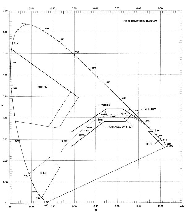
Figure 9.2‑1: Colours for aeronautical ground lights
Note: See subsection 14.3.6 for “AFRU with PAL Features”. |
9.3.1.1 If a pilot activated lighting (PAL) system is used to activate aerodrome lighting, the PAL is to turn ON all the lighting facilities which are required to be illuminated for night operations, unless the illumination of a required facility is achieved by other means, e.g. obstacle lights activated by photo-electric switches.
9.3.1.2 Where PAL is used to activate visual approach slope guidance systems (T‑VASIS or PAPI):
(a) activation of the PAL during daytime is to turn the visual approach slope guidance system ON to Day intensity, and leave all other aerodrome lighting extinguished;
(b) activation of the PAL during twilight is to turn the visual approach slope guidance system ON to Twilight intensity, and turn all other aerodrome lighting on to the only intensity available, or to Night intensity if multiple intensities are available;
Note: The night intensity will avoid the effect of glare and is normally adequate for operations during twilight hours. However, if an aerodrome, due to local conditions, requires the aerodrome lights to be set at a higher intensity than night intensity, it is permissible to provide Twilight intensity provided it does not produce glare. |
(c) activation of the PAL during night-time is to turn the visual approach slope guidance system ON to Night intensity, and turn all other aerodrome lighting on to the only intensity available, or to Night intensity if multiple intensities are available;
(d) once the lighting has been activated by the PAL, appropriate changes from Day to Twilight to Night intensities must take place automatically;
(e) the appropriate changes from Day to Twilight to Night operation shall take place under the control of a light sensitive switch or similar device;
(f) intensity must be the following percentage of full intensity:
(i) Day intensity — nominally 100%;
(ii) Twilight intensity — nominally 10%;
(iii) Night intensity — nominally 1%.
Note: For guidance in setting up the light sensitive switch, the following values of background luminance are suggested, though other values may be used if they provide a better match to local visibility conditions: (a) Day — background luminance above 500 cd/m2; (b) Twilight — between 50 and 500 cd/m2; (c) Night — below 50 cd/m2. |
9.3.1.3 The PAL must activate an aerodrome lighting system on detection of a coded carrier frequency signal from an aircraft air/ground VHF transmitter.
9.3.1.4 On receipt of the coded signal, the PAL control unit must go into the operate mode for a pre-set period. The minimum period that the lights remain ON shall be 30 minutes.
Note: The length of the period should be adjustable as local aerodrome operating conditions may require the lights to remain ON for a longer period. |
9.3.1.5 Ten minutes before the aerodrome lighting system is due to turn OFF, the PAL must cause the lights of at least the primary Illuminated Wind Direction Indicator (IWDI), in accordance with Paragraph 9.6.1.10, to commence to flash at approximately 50 cycles per minute (approximately 0.6 seconds ON and 0.6 seconds OFF), and continue to flash until either:
(a) the PAL system switches OFF, and all aerodrome lighting, including the IWDI lights, is extinguished; or
(b) the PAL system has been reset for another ON period.
9.3.1.6 When in operate mode (including the last 10 minutes) the receipt of another correctly coded signal must reset the PAL system to the beginning of the pre-set period.
9.3.2.1 The code required to activate the PAL system must be generated when the microphone button of the aircraft radio air/ground VHF transmitter is depressed and a radio frequency carrier signal is produced.
9.3.2.2 The correct code is to consist of three bursts of carrier signal each anywhere between 1 and 5 seconds long, with the last two code bursts completed within 24 seconds of the end of the first burst.
9.3.2.3 The gap between code bursts that the detector can tolerate shall be 0.1 seconds. (This is less than the time it takes to release and depress the aircraft microphone button.)
Note: Pilots are advised that the code they should send is three bursts of approximately 3 seconds, with at least 1 second between bursts, and the three bursts must be transmitted within 25 seconds. |
9.3.3.1 The VHF carrier detector must accept a carrier signal over the frequency range of 118 MHz to 136 MHz.
9.3.3.2 The receiver must be crystal controlled at a single frequency within the frequency range, with a channel separation of 25 kHz.
9.3.3.3 Only allocated frequencies must be used, to maintain order in the air/ground VHF band, and prevent interference to other facilities or users in the vicinity.
Note: Frequencies are allocated by the responsible authority. At this time Airservices Australia has the authority to allocate aeronautical frequencies including PAL frequencies. |
9.3.3.4 The frequency stability must be within ±0.0010% over the temperature range of -10°C to +70°C.
9.3.3.5 The minimum detectable input signal of the VHF carrier detector must be adjustable over a range to suit the operational requirements.
9.3.3.6 Under normal circumstances, to ensure activation of the PAL system by aircraft at approximately 15 NM from the aerodrome, the receiver sensitivity must be set at not less than 15 µV.
Note: 1. The suitability of the receiver sensitivity from different azimuth of the aerodrome will be flight tested. 2. The upper range of the receiver sensitivity may be of the order of 50 to 65 mV, but may be adjusted downward depending on whether nuisance operation is experienced from aircraft using the same PAL frequency at other locations. |
9.3.3.7 The VHF carrier detector bandwidth is to have the following characteristics:
±7.5 kHz within 3 dB of nominal
±16 kHz greater than 60 dB below nominal;
the spurious response is to be no less than 80 dB below nominal.
9.3.4.1 The PAL must be capable of having the following inputs:
(a) radio frequency activation signal, as described above;
(b) manual activation of the PAL. An ON/OFF switch must be provided for manual activation. When the switch is selected to ON the lighting system will be activated and remain on. When the switch is selected to OFF the PAL system must go into operate mode for the full timing cycle, including the ten minute turn-off warning. This is intended for use by authorised ground personnel, departing pilots, and maintenance technicians;
(c) remote control override of the PAL. If a PAL is provided at a controlled aerodrome, the circuitry of the PAL system must be such that when the controller is on duty, the PAL will be overridden by the controller.
9.3.5.1 The circuitry of the PAL system must be so designed that if the PAL fails for whatever reason, the aerodrome lighting can still be provided. This can be achieved by either:
(a) the lighting facilities being automatically turned ON if the PAL fails; or
(b) the provision of a by-pass switch to allow manual activation of the lights.
9.3.5.2 The mains supply to the equipment may be subject to electrical transients, typical of rural electrical distribution systems. The PAL system must be so designed that the electrical transients have no effect on the PAL system.
9.3.5.3 Following a PAL failure, on restitution of power the PAL must automatically commence a complete ‘Light ON’ cycle.
9.3.6.1 If the manual switches provided for PAL are either key operated switches, or enclosed in an area that requires key access, sufficient numbers of keys must be provided to persons who may have reason to gain access to the manual switches in the event of the PAL failing to respond to aerial VHF signal from incoming aircraft.
Note: The aerodrome operator is responsible for the allocation of access keys. |
9.3.6.2 The following persons are likely to be called upon to manually activate the aerodrome lighting:
(a) the agents of the airlines using the aerodrome;
(b) a representative from local operators of flying schools, fuelling agents, or aircraft maintenance organisations;
(c) representatives from the local hospital and/or emergency services;
(d) local police;
(e) where available, responsible person or persons living close to the aerodrome.
9.3.7.1 The PAL receiving antenna must be so located such that it will receive activating signals from aircraft both in the air and on the aerodrome movement area.
9.3.7.2 The PAL must be so designed that it will operate satisfactorily when connected to an antenna with the following specifications:
(a) unity gain with respect to a dipole;
(b) vertical polarisation;
(c) omnidirectional radiation pattern in the horizontal plane;
(d) voltage standing wave ratio when matched to the PAL antenna input of not greater than 1.5:1, over the frequency range of 118 to 136 MHz;
(e) height of the mounting above local ground level not less than 4.5 m.
9.3.8.1 Aerodrome operators are encouraged to use a PAL with message acknowledgment capability, which can provide positive response on receipt of pilot transmission and caution if the lighting cycle is within the 10 minute switch off phase.
Note: Such a PAL will require a radio transmitter licence. |
9.3.8.2 Where provided, the broadcast message must be brief, to minimise congestion on the frequency.
Note: Typical broadcast message should be of the form: “Name of aerodrome PAL ACTIVATED”. |
9.4.1.1 Under the Civil Aviation Regulations, CASA may determine that an object or a proposed object which intrudes into navigable airspace requires, or will be required to be provided with, obstacle lighting. Responsibility for the provision and maintenance of obstacle lighting on a building or structure rests with the owner of the building or structure. Within the limits of the obstacle limitation surfaces of an aerodrome, responsibility for the provision and maintenance of obstacle lighting on natural terrain or vegetation, where determined necessary for aircraft operations at the aerodrome, rests with the aerodrome operator.
9.4.1.2 In general, an object in the following situations would require to be provided with obstacle lighting unless CASA, in an aeronautical study, assesses it as being shielded by another lit object or that it is of no operational significance:
(a) for a runway intended to be used at night:
(i) if the object extends above the take-off climb surface within 3000 m of the inner edge of the take-off climb surface;
(ii) if the object extends above the approach or transitional surface within 3000 m of the inner edge of the approach surface;
(iii) if the object extends above the applicable inner, conical or outer horizontal surfaces;
(iv) if the object extends above the obstacle protection surface of the T-VASIS or PAPI installed at the aerodrome;
(v) a vehicle or other mobile objects, excluding aircraft, on the movement area, except aircraft service equipment and vehicles used only on aprons;
(vi) obstacles in the vicinity of taxiways, apron taxiways or taxilanes, except that obstacle lights are not to be installed on elevated ground lights or signs in the movement area.
(b) outside the obstacle limitation surfaces of an aerodrome, if the object is or will be more than 110 m above ground level.
9.4.1.3 Owners of tall buildings or structures below the obstacle limitation surfaces, or less than 110 m above ground level, may, of their own volition, provide obstacle lighting to indicate the presence of such buildings or structures at night. To ensure consistency and avoid any confusion to pilots, the obstacle lighting provided needs to conform with the standards specified in this Chapter.
9.4.1.4 In circumstances where the provision of obstacle marking is impracticable, obstacle lighting may be used during the day in lieu of obstacle marking.
9.4.2.1 Three types of lights are used for lighting obstacles. These are low intensity, medium intensity and high intensity lights, or a combination of such lights.
9.4.2.2 Low intensity obstacle lights are steady red lights and are to be used on non-extensive objects whose height above the surrounding ground is less than 45 m.
Note: A group of trees or buildings is regarded as an extensive object. |
9.4.2.3 Medium intensity obstacle lights are to be used either alone or in combination with low intensity lights, where:
(a) the object is an extensive one;
(b) the top of the object is 45 m or more above the surrounding ground; or
(c) CASA determines that early warning to pilots of the presence of the object is desirable.
9.4.2.4 There are three types of medium intensity obstacle lights:
(a) Flashing white light. Likely to be unsuitable for use in environmentally sensitive locations, and near built-up areas. May be used in lieu of obstacle markings during the day to indicate temporary obstacles in the vicinity of an aerodrome, for example construction cranes, etc. and are not to be used in other applications without specific CASA agreement.
(b) Flashing red light, also known as a hazard beacon. Is suitable for all applications, and is extensively used to mark terrain obstacles such as high ground.
(c) Steady red light. May be used where there is opposition to the use of a flashing red light, for example in environmentally sensitive locations.
9.4.2.5 High intensity obstacle lights are flashing white lights used on obstacles that are in excess of 150 m in height. As high intensity obstacle lights have a significant environmental impact on people and animals, it is necessary to consult with interested parties about their use. High intensity obstacle lights may also be used during the day, in lieu of obstacle markings, on obstacles that are in excess of 150 m in height, or are difficult to be seen from the air because of their skeletal nature, such as towers with overhead wires and cables spanning across roads, valleys or waterways.
9.4.3.1 One or more obstacle lights are to be located as close as practicable to the top of the object. The top lights are to be arranged so as to at least indicate the points or edges of the object highest above the obstacle limitation surface.
9.4.3.2 In the case of a chimney or other structure of like function, the top lights are to be placed sufficiently below the top (nominally 1.5 m to 3 m) so as to minimise contamination by smoke, etc.
9.4.3.3 In the case of a tower or antenna structure to be provided with high intensity obstacle lights, and the structure has an appurtenance such as a rod or antenna extending greater than 12 m above the structure, and it is not practicable to locate the high intensity obstacle light on top of the appurtenance, the high intensity obstacle light is to be located at the highest practicable point and, if practicable, have a medium intensity obstacle light (flashing white) mounted on the top.
9.4.3.4 In the case of an extensive object or a group of closely spaced objects, top lights are to be displayed at least on the points or edges highest in relation to the obstacle limitation surfaces, so as to indicate the general definition and extent of the objects. If two or more edges are at the same height, the edge nearest the runway threshold is to be lit. Where low intensity lights are used, they are to be spaced at longitudinal intervals not exceeding 45 m. Where medium intensity lights are used, they are to be spaced at longitudinal intervals not exceeding 900 m, and at least three are to be displayed on one side of the extensive obstacle to indicate a line of lights.
9.4.3.4A In the case of a wind farm whose wind turbines must have obstacle lighting, medium intensity lights are to be installed as follows:
(a) if any part of the wind turbine, including the rotating blades, penetrates the obstacle limitation surface (OLS) of an aerodrome, top lights must mark the highest point reached by the rotating blades;
Note: Because it is not practicable to install obstacle lights at the tip of the blades, these lights may be located on a separate structure, adjacent to the wind turbine, at a height that corresponds to the highest point of the rotating blade of the turbine. |
(b) if the rotating blades do not penetrate the OLS, the top lights must be placed on top of the generator housing;
(c) obstacle lights must be provided on a sufficient number of individual wind turbines to indicate the general definition and extent of the wind farm, with intervals between lit turbines not exceeding 900 m;
(d) all of the obstacle lights on a wind farm must be synchronised to flash simultaneously;
(e) the downward component of obstacle lighting may be shielded to the extent mentioned in either or both of the following sub-subparagraphs:
(i) so that no more than 5% of the nominal light intensity is emitted at or below 5o below horizontal;
(ii) so that no light is emitted at or below 10o below horizontal;
(f) to prevent obstacle light shielding by the rotating blades, 2 lights must be provided on top of the generator housing in a way that allows at least 1 of the lights to be seen from every angle in azimuth.
9.4.3.5 When the obstacle limitation surface concerned is sloping and the highest point above the obstacle limitation surface is not the highest point of the object, additional obstacle lights are to be placed on the highest part of the object.
9.4.3.6 When the top of the obstacle is more than 45 m above the level of the surrounding ground or the elevation of the tops of nearby buildings (when the obstacle is surrounded by buildings), the top lights are to be medium intensity lights. Additional low intensity lights are to be provided at lower levels to indicate the full height of the structure. These additional lights are to be spaced as equally as possible, between the top lights and ground level or the level of tops of nearby buildings, as appropriate. The spacing between the lights is not to exceed 45 m.
9.4.3.7 Where high intensity obstacle lights are used on an object other than a tower supporting overhead wires or cables, the spacing between the lights is not to exceed 105 m. Where the high intensity obstacle lights are used on a tower supporting wires or cables, they are to be located on three levels:
(a) at the top of the tower;
(b) at the lowest level of the catenary of the wires or cables; and
(c) at approximately midway between the two levels.
Note: In some cases this may require the bottom and middle lights to be located off the tower. |
9.4.3.8 The number and arrangement of lights at each level to be marked is to be such that the obstacle is indicated from every angle of azimuth. Where a light is shielded in any direction by an adjacent object, the light so shielded may be omitted but additional lights may be required in such a way so as to retain the general definition of the obstacle.
9.4.3.9 Illustrations of typical lighting of obstacles are shown below.

Figure 9.4‑1: Typical lighting of tall obstructions

Figure 9.4‑2: Typical lighting of a group of obstructions
Figure 9.4‑3: Typical lighting of horizontally extended obstructions

Figure 9.4‑4: Typical lighting of towers and large obstructions
9.4.4.1 Natural obstacles such as terrain and vegetation are normally extensive and the need for obstacle lighting will be assessed by CASA on an individual case basis. Where required, obstacle lights are to be provided as follows:
(a) if the obstacle is located within the approach area, the portion of the obstacle which is within the approach area is to be treated in the same manner as man-made obstacles for the provision of obstacle lights;
(b) if the obstacle is located outside the approach area, it is to be marked by sufficient number of lights on the highest and most prominent features, so placed that the obstacle can be readily identified.
9.4.5.1 At night and in poor visibility conditions, temporary obstacles in the approach area or on the movement area are to be marked with permanent or temporary red obstacle lights. The lights are to be so arranged that they clearly mark the height, limits and extent of the obstacle.
9.4.6.1 Low intensity obstacle lights, for general applications, are to have the following characteristics:
(a) fixed lights showing red;
(b) a horizontal beam spread that results in 360° coverage around obstacle;
(c) a peak intensity of 100 cd minimum;
(d) a vertical beam spread (to 50% of peak intensity) of 10°;
(e) a vertical distribution with 100 cd minimum at +6° and +10° above the horizontal; and
(f) not less than 10 cd at all elevation angles between –3° and +90° above the horizontal.
Notes: 1. The intensity level is higher than ICAO standards because in Australia only obstacles assessed as significant to aircraft operations are required to be provided with obstacle lighting. 2. Currently the intensity requirement is normally met by a double-bodied light fitting which also provides a degree of redundancy. 3. Double-bodied light fittings should be orientated so that they show the maximum illuminated surface towards the predominant, or more critical, direction of aircraft approach. |
Notes: (Contd.) 4. For objects that do not infringe the obstacle limitation surfaces, and where CASA has not determined that obstacle lights are required, if the object owner wishes, of their own volition, to provide obstacle lights, it is sufficient for these low intensity obstacle lights to have the following intensity distribution: peak intensity 32 cd minimum, vertical beam spread of 10, and 32 cd minimum at +6 and +10 elevation. |
9.4.6.2 Low intensity obstacle lights, used to indicate taxiway obstacles or unserviceable areas of the movement area, are to have a peak intensity of 10 cd minimum.
9.4.7.1 Medium intensity obstacle lights are to be flashing or steady red lights or flashing white lights, visible in all directions in azimuth.
9.4.7.2 The frequency of flashes is to be between 20 and 60 flashes per minute.
9.4.7.3 The peak effective intensity is to be 2,000 25% cd with a vertical distribution as follows:
(a) vertical beam spread is to be 3 minimum (beam spread is defined as the angle between two directions in a plane for which the intensity is equal to 50% of the lower tolerance value of the peak intensity);
(b) at -1 elevation, the intensity is to be 50% minimum and 75% maximum of lower tolerance value of the peak intensity; and
(c) at 0 elevation, the intensity is to be 100% minimum of the lower tolerance value of the peak intensity.
9.4.7.4 Where the flashing white light is used in lieu of obstacle marking during the day to indicate temporary obstacles in the vicinity of an aerodrome, in accordance with Paragraph 9.4.2.4(a), the peak effective intensity is to be increased to 20,000 25% cd when the background luminance is 50 cd/m² or greater.
9.4.8.1 High intensity obstacle lights are flashing white lights.
9.4.8.2 The effective intensity of a high intensity obstacle light located on an object other than a tower supporting overhead wires or cables is to vary depending on background luminance as follows:
(a) 200,000 25% cd effective intensity at a background luminance of above 500 cd/m² (day);
(b) 20,000 25% cd effective intensity at a background luminance of between 50-500 cd/m² (dusk or dawn);
(c) 2,000 25% cd effective intensity at a background luminance of below 50 cd/m² (night).
9.4.8.3 The effective intensity of a high intensity obstacle light located on a tower supporting overhead wires or cables is to vary depending on background luminance as follows:
(a) 100,000 25% cd effective intensity at a background luminance of above 500 cd/m² (day);
(b) 20,000 25% cd effective intensity at a background luminance of between 50-500 cd/m² (dusk or dawn);
(c) 2,000 25% cd effective intensity at a background luminance of below 50 cd/m² (night).
9.4.8.4 High intensity obstacle lights located on an object other than a tower supporting overhead wires or cables are to flash simultaneously at a rate between 40-60 flashes per minute.
9.4.8.5 High intensity obstacle lights located on a tower supporting overhead wires or cables are to flash sequentially; first the middle light, second the top light, and last the bottom light. Cycle frequency is to be 40 - 60 per minute and the intervals between flashes of lights are to approximate the following ratios:
Table 9.4‑1
Flash interval between: | Ratio of cycle time |
middle and top light | 1/13 |
top and bottom light | 2/13 |
bottom and middle light | 10/13 |
9.4.8.6 To minimise environmental impact, unless otherwise directed by CASA, the installation setting angles for high intensity obstacle lights are to be:
Table 9.4‑2
Height of light unit above terrain | Angle of the peak of the beam above the horizontal |
greater than 151 m AGL | 0° |
122 m to 151 m AGL | 1° |
92 m to 122 m AGL | 2° |
less than 92 m AGL | 3° |
9.4.9.1 Where the installation of normal obstacle lights is deemed impracticable or undesirable for aesthetic or other reasons, floodlighting of obstacles may be an acceptable alternative. However, floodlighting is not to be used unless with the concurrence of the relevant CASA office.
9.4.9.2 In general, floodlighting is not suitable if:
(a) the structure is skeletal as a substantially solid surface or cladding with satisfactory reflectance properties are required; or
(b) there is high background lighting level.
9.4.9.3 The floodlighting colour is to be white. Illumination of the obstacle is to cover all directions of azimuth over the full height portion of the obstacle which needs to be illuminated and is to be uniform around the circumferences of the obstacle.
9.4.9.4 The minimum level of luminance is to be 5 cd/m² at all points.
Note: Based on a reflectance factor of 50% for white paint, this would require illuminance of at least 10 lux. For concrete with typical reflectance factor of 40%, the required illuminance would be at least 12.5 lux. Materials with reflectance factors less than 30% are unlikely to be suitable for floodlighting. |
9.4.9.5 The light fittings are to be spaced evenly around the structure, at not more than 120° with at least two fittings at each location. At each location the fittings are to be on separate circuits and separately fused.
9.4.10.1 It is important that obstacle lights provided are in working condition when they are required to be on. The owners of obstacle lights needs to establish a pro-active maintenance program to minimise light outage.
9.4.10.2 For obstacle lights located within the obstacle limitation surface area of the aerodrome, the aerodrome operator is to establish a monitoring program, which is to include:
(a) visual observation of the obstacles lights at least once every 24 hours (see note); and
(b) where a medium or high intensity obstacle light is located such that it is not readily observable visually:
(i) establish a procedure whereby such a light would be visually monitored within every 24 hour period; or
(ii) install an automatic visual or audio alarm indicator at an aerodrome location generally occupied by aerodrome personnel.
Note: At smaller aerodromes with a low level of night aircraft operations, this period may be extended with the agreement of the relevant CASA office. |
9.4.10.3 For an obstacle located within the OLS area of the aerodrome, the following requirements apply:
(a) if there is an obstacle light outage, the aerodrome operator must:
(i) immediately request the NOTAM office to advise pilots of the details of the outage; and
(ii) as soon as practicable liaise with the owner of the obstacle light so that the outage is repaired as quickly as practicable;
(b) if the aerodrome has been notified by CASA that it must close upon the failure of a specified obstacle light considered by CASA to be essential for safety, the aerodrome operator must immediately notify CASA of the failure.
Note: Information on requesting NOTAM action is in Chapter 10, Section 10.3. |
9.4.10.3A The aerodrome operator’s Aerodrome Manual must include:
(a) the procedures to be followed when an obstacle light outage occurs; and
(b) details of any CASA notification that the aerodrome must close upon the failure of a specified obstacle light considered by CASA to be essential for safety.
9.4.10.4 For obstacles located outside the obstacle limitation surface area of an aerodrome, the owners of the lights need to establish a program to monitor the lights and report light failures. The reporting point for obstacle light failure is normally the nearest CASA office. When an obstacle light is unserviceable, the matter needs to be reported immediately to the relevant CASA office so that a NOTAM warning pilots of the light outage can be initiated.
9.5.1.1 An aerodrome beacon is to be provided if it is determined by CASA that such a visual cue is operationally necessary.
9.5.1.2 The following factors will be used in determining operational necessity:
(a) whether the aerodrome is intended to be used at night by aircraft navigating predominantly by visual means;
(b) the type and quantity of air traffic;
(c) the presence of other visual or radio aids;
(d) whether the location is subject to frequent periods of reduced visibility;
(e) whether it is difficult to locate the aerodrome from the air due to surrounding lights or terrain.
9.5.1.3 Where provided, the aerodrome beacon is to be located on or adjacent to the aerodrome in an area of low ambient background lighting. In addition, the aerodrome beacon is to be sited so that it is neither shielded by obstacles nor dazzling to a pilot making an approach to land.
9.5.1.4 At international aerodromes or aerodromes in built-up areas, the aerodrome beacon is to show two flashes, one white and the other coloured, so that they produce alternate white and colour flashes. For land aerodromes, the colour is to be green, for water aerodromes, the colour is to be yellow.
9.5.1.5 At other locations, white flashes only is satisfactory.
9.5.1.6 The frequency of total flashes must be from 20 to 30 per minute.
Note: Older beacons with a frequency of flashes in the range of 12 to 20 per minute are acceptable, until the next replacement or upgrade of the beacon. |
9.5.1.7 The light from the beacon is to be visible from all angles of azimuth.
9.5.1.8 The light intensity distribution of the aerodrome beacon must be in accordance with Table 9.5‑1:
Table 9.5‑1: Aerodrome beacon light intensity distribution
Elevation angle (in degrees) | Minimum effective intensity of white flashes (in candelas) |
1 to 2 | 25 000 |
2 to 8 | 50 000 |
8 to 10 | 25 000 |
10 to 15 | 5 000 |
15 to 20 | 1 000 |
9.5.1.9 The effective intensity of colour flashes is to be not less than 0.15 times the intensity of the white flashes at the corresponding angle of elevation.
9.5.1.10 Where provided, information on the colour coding, flash rate and location (if not in the immediate vicinity of the aerodrome) of the aerodrome beacon is to be published in the aerodrome ERSA entry.
9.6.1.1 At an aerodrome intended for night use, at least one wind direction indicator is to be lit.
Note: Wind direction indicators must be provided in accordance with Section 8.7. |
9.6.1.2 If a WDI is provided in the vicinity of a runway threshold to provide surface wind information for pilots engaged in instrument straight-in approach and landing operations, and such operations are to be conducted at night, then the wind direction indicator is to be lit.
9.6.1.3 An illuminated wind direction indicator (IWDI) must be illuminated by floodlighting from above.
9.6.1.3A An IWDI installed on or after 1 July 2011 must be illuminated by at least 4 lamp units which together provide between 100 and 600 lux illumination on any point of the horizontal plane passing through the top of the IWDI sleeve at the supporting pole end for the 360o area swept by the fully extended sleeve.
Note: An acceptable method of testing for illumination compliance is to measure illumination levels on the horizontal plane passing through the top of the sleeve at the pole end. Measurements should be taken at 1 m intervals starting at the pole and working outwards on a radial to the pole to a range equal to the length of the fully extended sleeve. The outermost interval on each radial may be less than 1 m to correspond with the actual length of the sleeve. The radials should be at 30o intervals. Each reading should be in the range 100 to 600 lux. |
9.6.1.3B The lighting must have:
(a) accurate colour rendering; and
(b) no perceptible warm-up or restrike delay.
9.6.1.3C An IWDI installed before 1 July 2011 must be illuminated:
(a) in accordance with paragraphs 9.6.1.3A and 9.6.1.3B; or
(b) as follows:
(i) four 200W 240V tungsten filament general purpose lamps in either vertical elliptical industry reflectors, or round deep bowl reflectors, between 1.8 m and 2.2 m above the mid-height of the sleeve mounting, and between 1.7 m and 1.9 m radial distance from the axis of rotation of the wind sleeve; or
(ii) eight 120W 240V PAR 38 flood lamps in reflectorless fittings, between 1.8 m and 2.2 m above the mid-height of the wind sleeve mounting, and between 1.7 m and 1.9 m radial distance from the axis of the rotation of the wind sleeve; or
(iii) some other method of floodlighting which:
(A) produces lighting equivalent to that provided under sub subparagraph 9.6.1.3C (b) (i) or (ii); and
(B) has accurate colour rendering; and
(C) has no perceptible warm-up or restrike delay.
9.6.1.4 The floodlighting is to be aimed and shielded to ensure that it causes neither glare nor distraction to pilots.
Note: An acceptable method of testing for compliance is as follows: from an observer’s standing position on ground that is level with the base of the pole there should be no glare at a range of 25 m or more. The assessment need only be made from those directions likely to be viewed from landing, taking-off or taxiing aircraft. |
9.6.1.5 If only one wind direction indicator is lit at an aerodrome and there are two or more lit runways, control of the lighting of the wind direction indicator is to be incorporated in the runway lighting control for each runway, so that energising any runway lighting system will automatically energise the lighting of the wind direction indicator.
9.6.1.6 Where more than one wind direction indicator can be lit, control of the lighting of each wind direction indicator is to be incorporated in the runway lighting control for the operationally related runway.
9.6.1.7 If the electricity supply to a wind direction indicator is provided from a runway lighting circuit for which intensity control is provided, a uniform intensity is required for the wind direction indicator irrespective of the intensity setting of the runway lighting.
9.6.1.8 Where a PAL is installed the wind direction indicator lighting is to be programmed in such a way that 10 minutes before the end of the aerodrome lighting ‘ON’ period, the lights of the wind direction indicator will commence to flash, at approximately 50 cycles per minute, and continue to flash until either:
(a) the PAL system switches off, and all aerodrome lighting, including the wind direction indicators, is extinguished; or
(b) the PAL system has been reset for another ‘ON’ period.
9.6.1.9 If the PAL system is reset for another ‘ON’ period, the lights of the wind direction indicator are to return to steady lighting.
9.7.1.1 A simple approach lighting system is a lighting system intended for a non-instrument or a non-precision approach runway. Standards for this system are not included in this Chapter as there is no operational credit for such systems.
Note: Standard runway edge and threshold lights, supplemented by a visual approach slope indicator system have been found adequate for non-instrument and non-precision approach runways. |
9.7.2.1 A precision approach Category I lighting system must be provided to serve a precision approach runway Category I, as far as physically practicable.
Location
9.7.2.2 A precision approach Category I lighting system must consist of a row of lights on the extended centreline of the runway extending, wherever possible, over a distance of 900 m from the runway threshold, with a row of lights forming a crossbar 30 m in length at a distance of 300 m from the runway threshold.
Note: The installation of an approach lighting system of less than 900 m in length may result in operational limitations on the use of the runway. |
9.7.2.3 The lights forming the crossbar must be:
(a) as nearly as practicable in a horizontal straight line at right angles to, and bisected by, the line of the centreline lights; and
(b) spaced so as to produce a linear effect, except that gaps may be left on each side of the centreline provided:
(i) the spacing of gaps is kept to a minimum to meet local requirements; and
(ii) no gap exceeds 6 m.
Notes: 1. Spacings for the crossbar lights between 1 m and 4 m are in use. Gaps on each side of the centreline may improve directional guidance when approaches are made with a lateral error, and facilitate the movement of rescue and firefighting vehicles. 2. See ICAO Annex 14, Attachment A, Section 11 for guidance on installation tolerances. |
9.7.2.4 The lights forming the centreline must be placed at longitudinal intervals of 30 m with the innermost light located 30 m from the threshold.
9.7.2.5 The lighting system must lie as nearly as practicable in the horizontal plane passing through the threshold, and be such that:
(a) no object, other than an ILS azimuth antenna, protrudes through the plane of the approach lights within a distance of 60 m from the centreline of the system; and
(b) no light, other than a light located within the central part of a crossbar or a centreline barrette (not their extremities), is screened from an approaching aircraft.
Antenna protrusions
9.7.2.6 An ILS azimuth antenna protruding through the plane of the lights must be treated as an obstacle and marked and lighted accordingly.
Characteristics
9.7.2.7 The centreline and crossbar lights of a precision approach Category I lighting system must:
(a) be fixed lights showing variable white; and
(b) for each centreline light position — consist of:
(i) 1 light source in the innermost 300 m of the centreline, 2 light sources in the central 300 m of the centreline and 3 light sources in the outer 300 m of the centreline, to provide distance information; or
(ii) a barrette.
9.7.2.8 A barrette must be:
(a) at least 4 m in length; and
(b) if composed of lights approximating to point sources — composed of such lights uniformly spaced at intervals of not more than 1.5 m.
(a) be flashed twice a second in sequence, beginning with the outermost light and progressing toward the threshold to the innermost light of the system; and
(b) be of such electrical circuit design that it can be operated independently of the other lights of the approach lighting system.
9.7.2.10 If the centreline consists of lights as described in subparagraph 9.7.2.7 (a):
(a) crossbars of lights (additional to the crossbar of lights at 300 m from the threshold) must be provided at 150 m, 450 m, 600 m and 750 m from the threshold; and
(b) the lights forming each crossbar must be:
(i) as nearly as practicable in a horizontal straight line at right angles to, and bisected by, the line of the centreline lights; and
(ii) spaced so as to produce a linear effect, except that gaps may be left on each side of the centreline provided:
(A) the number of gaps is kept to a minimum to meet local requirements; and
(B) no gap exceeds 6 m.
9.7.2.11 Where the additional crossbars described in 9.7.2.10 are incorporated in the system, the outer ends of the crossbars must lie on two straight lines that converge to meet the runway centreline 300 m from threshold.
9.7.2.12 Figure 9.7-1 below illustrates both kinds of precision approach Category I lighting configurations mentioned in this section.
9.7.2.13 The lights must be in accordance with the specifications of Section 9.8, Figure 9.8-1.
Note: ICAO Annex 14, Attachment A, Section 11 provides information on the flight path envelopes used in the design of these lights. |

Figure 9.7-1: Precision approach Category I lighting systems
9.7.3.1 A precision approach Category II and Category III lighting system must be provided to serve a precision approach runway Category II or III.
Note: Where a precision approach Category II and Category III lighting system is provided, touchdown zone lights must also be provided. |
Location
9.7.3.2 The approach lighting system must consist of a row of lights on the extended centreline of the runway, extending, wherever possible, over a distance of 900 m from the runway threshold, with:
(a) 2 side rows of lights, extending 270 m from the threshold; and
(b) 2 crossbars, 1 at 150 m and 1 at 300 m from the threshold, as shown in Figure 9.7.2.
Note: The length of 900 m is based on providing guidance for operations under Categories I, II and III conditions. Reduced lengths may support Categories II and III operations but may impose limitations on Category I operations. |
9.7.3.3 The centreline lights must be at longitudinal intervals of 30 m, with the innermost lights located 30 m from the threshold.
9.7.3.4 The side row lights must be placed:
(a) on each side of the centreline; and
(b) at a longitudinal spacing equal to that of the centreline lights; and
(c) with the first light located 30 m from the threshold; and
(d) so that the lateral spacing (or gauge) between the innermost lights of the side rows is not less than 18 m nor more than 22.5 m, but in any event equal to that of the touchdown zone lights.
9.7.3.5 The crossbar provided at 150 m from the threshold must fill in the gaps between the centreline and side row lights.
9.7.3.6 The crossbar provided at 300 m from the threshold must extend on both sides of the centreline lights to a distance of 15 m from the centreline.
9.7.3.7 If the centreline beyond a distance of 300 m from the threshold consists of lights as described in subparagraph 9.7.3.12 (b), additional crossbars of lights must be provided at 450 m, 600 m and 750 m from the threshold.
9.7.3.8 Where the additional crossbars described in 9.7.3.7 are incorporated in the system, the outer ends of these crossbars must lie on two straight lines that converge to meet the runway centreline 300 m from the threshold.
9.7.3.9 The lighting system must lie as nearly as practicable in the horizontal plane passing through the threshold, and be such that:
(a) no object, other than an ILS azimuth antenna, may protrude through the plane of the approach lights within a distance of 60 m from the centreline of the system; and
(b) no light, other than a light located within the central part of a crossbar or a centreline barrette (not their extremities), may be screened from an approaching aircraft.
Antenna protrusions
9.7.3.10 An ILS azimuth antenna protruding through the plane of the lights must be treated as an obstacle and marked and lighted accordingly.
Characteristics
9.7.3.11 The centreline of a precision approach Categories II and III lighting system for the first 300 m from the threshold must consist of barrettes showing variable white, except that, where the threshold is displaced 300 m or more, the centreline may consist of single light sources showing variable white.
9.7.3.12 Beyond 300 m from the threshold, each centreline light position must consist of 1 of the following which all must show variable white:
(a) 1 barrette as used on the inner 300 m;
(b) 2 light sources in the central 300 m of the centreline, and 3 light sources in the outer 300 m of the centreline.
9.7.3.13 A barrette must be:
(a) at least 4 m in length; and
(b) if composed of lights approximating to point sources — composed of such lights uniformly spaced at intervals of not more than 1.5 m.
9.7.3.14 If the centreline beyond a distance of 300 m from the threshold consists of barrettes as described in subparagraph 9.7.3.12 (a), each barrette must be supplemented by a capacitor discharge light which must:
(a) be flashed twice a second in sequence, beginning with the outermost light and progressing toward the threshold to the innermost light of the system; and
(b) be of such electrical circuit design that it can be operated independently of the other lights of the approach lighting system.
9.7.3.15 Each side row of lights must consist of a barrette:
(a) whose lights show red; and
(b) whose length and light spacing must be equal to the length and light spacing of the barrettes in the touchdown zone.
9.7.3.16 The lights forming the crossbars must be:
(a) fixed lights showing variable white; and
(b) uniformly spaced at intervals of not more than 2.7 m.
9.7.3.17 The intensity of the red lights must be compatible with the intensity of the white lights.
9.7.3.18 The lights must be in accordance with the specifications of Section 9.8, Figure 9.8-1 and Figure 9.8-2.
Note: ICAO Annex 14, Attachment A, Section 11 provides information on the flight path envelopes used in the design of these lights. |
.

Figure 9.7-2: Precision approach lighting system, Categories II and III
9.8.1.1 Except for Paragraph 9.11.1.4, the collective notes for Section 9.11 apply to this Section.
9.8.1.2 Average intensity ratio. The ratio between the average intensity within the ellipse defining the main beam of a typical new light and the average intensity of the main beam of a new runway edge light is to be as follows:
(a) Figure 9.8‑1 Approach centreline and crossbars ― 1.5 to 2.0 (white light)
(b) Figure 9.8‑2 Approach side row ― 0.5 to 1.0 (red light)

 Figure 9.8‑1: Isocandela diagram for approach centreline light and cross bars (white light)
Notes: 1. Curves calculated on formula 
2. Vertical setting angles of the lights must be such that the following vertical coverage of the main beam will be met:
Distance from threshold Vertical main beam coverage
Threshold to 315 m 0º – 11º
316 m to 475 m 0.5º – 11.5º
476 m to 640 m 1.5º – 12.5º
641 m and beyond 2.5º – 13.5º (as illustrated above)
3. Lights in crossbars beyond 22.5 m from the centre line must be toed-in 2 degrees. All other lights must be aligned parallel to the centre line of the runway.
4. See collective notes at Paragraph 9.8.1.

Figure 9.8‑2: Isocandela Diagram for approach side row light (red light)
Notes: 1. Curves calculated on formula
2. Toe-in 2 degrees
3. Vertical setting angles of the lights must be such that the following vertical coverage of the main beam will be met:
Distance from threshold Vertical main beam coverage
Threshold to 115 m 0.5º – 10.5º
116 m to 215 m 1.0º – 11º
216 m and beyond 1.5º – 11.5º (as illustrated above)
4. See collective notes at Paragraph 9.8.1.
9.9.1.1 A visual approach slope indicator system shall be provided to serve the approach to a runway, whether or not the runway is served by electronic approach slope guidance, where one of the following applies:
(a) The runway is regularly used by jet-propelled aeroplanes engaged in air transport operations.
(b) CASA directs that visual approach slope guidance be provided, because it has determined that such a visual aid is required for the safe operation of aircraft.
9.9.1.2 In making a determination that visual approach slope guidance is required, CASA will take into account the following:
(a) The runway is frequently used by other jet-propelled aeroplanes, or other aeroplanes with similar approach guidance requirements.
(b) The pilot of any type of aeroplane may have difficulty in judging the approach due to:
(i) inadequate visual guidance such as is experienced during an approach over water or featureless terrain by day or in the absence of sufficient extraneous lights in the approach area by night;
(ii) misleading approach information such as that produced by deceptive surrounding terrain, runway slope, or unusual combinations of runway width, length and light spacing;
(iii) a displaced threshold.
(c) The presence of objects in the approach area may involve serious hazard if an aeroplane descends below the normal approach path, particularly if there are no non-visual or other visual aids to give warning of such objects.
(d) Physical conditions at either end of the runway present a serious hazard in the event of an aeroplane undershooting or overrunning the runway.
(e) Terrain or prevalent meteorological conditions are such that the aeroplane may be subjected to unusual turbulence during approach.
9.9.1.3 CASA may direct that a visual approach slope indicator system be provided for temporary use only, for example due to a temporary displaced threshold, or during works in progress.
9.9.1.4 The following visual approach slope indicator systems are approved for use in Australian civil aerodromes:
(a) T-VASIS;
(b) AT-VASIS;
(c) Double-sided PAPI; and
(d) PAPI.
9.9.1.5 The standard installations must be:
(a) At international aerodromes, T-VASIS, or double-sided PAPI. Where this is impracticable, an AT-VASIS or PAPI is acceptable.
(b) At aerodromes other than international aerodromes, AT-VASIS or PAPI, except where (c) below applies.
(c) At aerodromes where CASA has determined that additional roll guidance is required, and/or high system integrity is necessary, T-VASIS or double-sided PAPI.
(d) AT-VASIS and PAPI must be installed on the left side of the runway, unless this is impracticable.
9.9.1.6 Where a T-VASIS is to be replaced by a PAPI, a double-sided PAPI must be provided.
9.9.1.7 Where more than one visual approach slope indicator system is provided at an aerodrome, to avoid confusion, the same type of approach slope indicator system must be used at each end of a runway. If there is more than one runway, the same type of approach slope indicator system must be used on all runways of similar reference code number.
9.9.1.8 Where a visual approach slope indicator system is provided for temporary use only, in accordance with 9.9.1.3, then 9.9.1.7 need not apply.
9.9.1.9 The choice of T-VASIS or PAPI is a matter between the aerodrome operator and airline operators using the runway. For capital city runways used by a range of medium and large jet aeroplanes, T-VASIS would be a better visual aid.
9.9.2.1 An obstacle assessment surface (OAS) must be surveyed and assessed for obstacles for each end of the runway where a T-VASIS, AT-VASIS, double‑sided PAPI or PAPI is to be provided. Standards of OAS are as follows and an OAS is illustrated below:
(a) Baseline: Width 150 m, coincident with the existing baseline for the approach surface;
(b) Slope: 1.9º;
(c) Splay: 7.5º outwards, commencing from the ends of the baseline;
(d) Length: 9 km from the baseline.
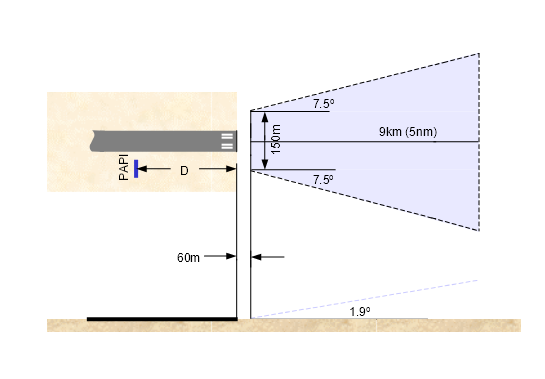
Figure 9.9‑1: Illustration of an Obstacle Assessment Surface for 3° approach slope
9.9.2.2 The aerodrome operator must check any penetration by, or proximity to, objects such as radio masts, buildings etc. and terrain, of the Obstacle Assessment Surface as specified in Paragraph 9.9.2.1. Where one or more obstacles are found, or where high ground lies close to the approach path, the relevant CASA Office must be requested to conduct an aeronautical study to determine whether the obstacle(s) or terrain could adversely affect the safety of aircraft operations.
9.9.2.3 Where practicable, objects above the assessment surface must be removed, except where CASA determines that the object would not adversely affect the safety of operations.
9.9.2.4 If the study determines that safety could be adversely affected, and it is not practicable to remove the object, then one or more of the following measures should be undertaken:
(a) suitably raise the approach slope of the system – to a maximum of 3.3° where the runway is used by jet propelled aeroplanes, or 4° for other aeroplanes: the OAS slope can then be raised by the same amount, e.g. for a 3.3° slope the OAS can become 2.2° instead of 1.9°;
(b) reduce the azimuth spread so that the obstacle is outside the confines of the beam;
(c) displace the axis of the system and its associated OAS by up to 5°;
(d) suitably displace the threshold; and
(e) if (d) is impracticable, suitably displace the system upwind of the threshold to provide an increase in threshold crossing height equal to the height of the obstacle penetration.
9.9.3.1 A T-Visual Approach Slope Indicator System (T-VASIS) is a set of lights so arranged that the pattern seen by the pilot varies according to his position (up or down, left or right) relative to the desired approach path. Where installed in the runway strip, it provides the pilot with visual cues about his or her actual descent path relative to the desired descent path.
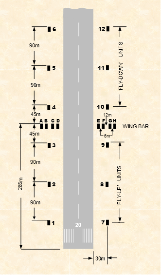
Figure 9.9‑2: T-VASIS Layout
9.9.3.2 A T-VASIS must consist of twenty light units symmetrically disposed about the runway centreline in the form of two wing bars of four light units each, with bisecting longitudinal lines of six lights, and laid out as shown in Figure 9.9‑2.
9.9.3.3 An AT-VASIS must consist of ten light units arranged on one side of the runway in the form of a single wing bar of four light units with a bisecting longitudinal line of six lights.
9.9.3.4 The light units must be constructed and arranged in such a manner that the pilot of an aeroplane during an approach will:
(a) When above the correct approach slope, see an inverted white ‘T’ pattern comprising the white wing bar(s) lights, and one, two or three white ‘fly-down’ lights, the more fly-down lights being visible, the higher the pilot is above the correct approach slope.
(b) When on the correct approach slope, see a line of white wing bar(s) lights.
(c) When below the correct approach slope, see a white ‘T’ pattern comprising the white wing bar(s) lights and one, two or three white ‘fly-up’ lights, the more fly-up lights being visible the lower the pilot is below the correct approach slope; and when well below the correct approach slope, see a red ‘T’ pattern with the wing bar(s) and the three fly-up lights showing red.
9.9.3.5 Siting a T-VASIS or AT-VASIS. The siting of a T-VASIS or AT-VASIS must be such that:
(a) The light units must be located as shown in Figure 9.9‑2, subject to the tolerances given in Table 9.9‑1.
(b) The light units forming the wing bars, or the light units forming a fly-down or a fly-up matched pair, must be mounted so as to appear to the pilot of an approaching aeroplane to be substantially in a horizontal line. The light units must be mounted as low as possible and must be frangible.
9.9.3.6 Characteristics of the T-VASIS light units. The characteristics of the T-VASIS light units must be such that:
(a) The system must be suitable for both day and night operations.
(b) A suitable intensity control must be provided to allow adjustments to meet the prevailing conditions and to avoid dazzling the pilot during approach and landing.
(c) The light distribution of the beam of each light unit must be of fan shape showing over a wide arc in azimuth in the approach direction. The wing bar light units shall produce a beam of white light from 1° 54’ vertical angle up to 6° vertical angle and a beam of red light from 0° to 1° 54’ vertical angle. The fly-down light units must produce a beam of white light extending from an elevation of 6° down to approximately the approach slope, where it must have a sharp cut-off. The fly-up light units must produce a beam of white light from approximately the approach slope down to 1° 54’ vertical angle and a beam of red light below 1° 54’ vertical angle. The angle of the top of the red beam in the wing bar units and fly-up units may be increased to provide obstacle clearance.
(d) The colour transition from white to red must be so as to appear to an observer at a distance of not less than 300 m, to occur over a vertical angle of not more than 15’. Immediately below this transition sector the intensity of the completely red beam must not be less than 15% of the intensity of the completely white beam immediately above the transition sector.
(e) The beam of light produced by the light units must show through an angle of at least 1° 30’ above and below the approach slope both by day and by night and in azimuth through not less than 10° by day and not less than 15° by night. The effective visual range of the light units in clear weather must be at least 7.4 km over the above angles.
Notes: 1. Past practice in Australia has been to increase the night azimuth to 30°. 2. Where obstacles infringe into this wider azimuth, the obstacles should be removed where practicable. Alternatively, the azimuth spread may be suitably restricted. |
(f) The light units must be so designed that deposits of condensation, dirt, etc. on optically transmitting or reflecting surfaces must interfere to the least possible extent with the light signals and must in no way affect the elevation of the beams or the contrast between the red and white signals. The construction of the light units must be such as to minimise the probability of the slots being wholly or partially blocked by snow or ice where these conditions are likely to be encountered.
9.9.3.7 Approach slope and elevation settings of light beams. The approach slope and elevation settings of light beams must be such that:
(a) An approach slope that is operationally satisfactory is to be selected for each runway. The standard approach slope is 3º (1:19 nominal), and with an eye height over threshold of 15 m.
(b) When the runway on which a T-VASIS is provided is equipped with an ILS, the siting and elevation of the light units must be such that the T-VASIS approach slope is compatible with the ILS glide path. A T-VASIS eye-height over the threshold 1 m higher than the ILS glide path has been found to satisfy most aeroplanes.
(c) The light beams from the corresponding light units on opposite sides of the runway must have the same recognition angle. The fly-up and fly-down light units of the ‘T’ must appear with uniform steps as the approach slope changes.
(d) The elevation of the beams of the wing bar light units on both sides of the runway must be the same. The elevation of the top of the beam of the fly-up light unit nearest to each wing bar, and the bottom of the beam of the fly-down light unit nearest to each wing bar, must be equal and must correspond to the approach slope. The cut-off angle of the top of the beams of successive fly-up units shall decrease by 5’(±½’) of arc in angle of elevation at each successive unit away from the wing bar. The cut-in angle of the bottom of the beam of the fly-down light units must increase by 7’(±½’) of arc at each successive unit away from the wing bar.
(e) The elevation setting of the top of the red light beams of the wing bar and fly-up light units must be such that, during an approach, the pilot of an aeroplane, to whom the wing bar and three fly-up units are visible, would clear all objects in the approach area by a safe margin, if any such light did not appear red.
9.9.3.8 Clearance from movement areas. Light unit must not be sited closer than 15 m from the edge of the runway. Light units should be sited at least 15 m from the edge of a taxiway but should circumstances require units to be closer than this distance the particular case should be referred to CASA.
9.9.3.9 System dimensions. Tabulated below are system dimensions, with allowable tolerances. These values apply to design, installation and subsequent maintenance:
Table 9.9‑1
Item | Standard | Allowable Tolerance |
Eye height over threshold | 15 m 1,² | +1 m –3 m |
Approach slope 3 | 3° (1: 19 nominal) | |
Distance of longitudinal line of light units from runway edge 4 | 30 m | ±3 m |
Leg light unit spacing | 45 m
90 m | ±4.5 m
±9 m |
Clearance from pavements | 15 m 5 | |
Alignment of each light unit | Parallel to runway centreline | ±1° |
Light units in a wing bar
Fronts of light units
Height of light units |
Aligned
Aligned
|
±25 mm
±25 mm
|
Levelling of light units | Level | To the accuracy of the precision engineers level. 6 |
1 When the runway on which a T-VASIS is provided is equipped with an ILS, the siting and elevations of the T-VASIS shall be such that the visual approach slope conforms as closely as possible to the Glide Path of the ILS. 2 A T-VASIS eye height over threshold 1 m higher than the ILS Glide Path satisfies most aircraft. 3 The use of a different approach slope requires prior approval from CASA. 4 The edge of the runway is defined as the distance from the runway centreline, which is half the nominal width of the runway and ignores sealed shoulders. 5 A minimum clearance between any part of a T-VASIS light unit (but not the foundation slab) and an adjacent runway or taxiway pavement. 6 This includes end-for-ending the level to ensure no inaccuracy of the instrument. |
9.9.3.10 The aerodrome operator must ensure that the immediate surround of each unit is kept free of grass. Tall grass immediately in front of the light unit could provide conflicting light signals. Grass growing near to the box on any side could result in the fine settings being disturbed during power mowing operations.
9.9.3.11 Current settings. The following information is provided for guidance only of aerodrome operators. For existing installations, the recommended lamp current, the approximate series current and approximate light intensities are shown in Table 9.9‑2 and Table 9.9‑3.
Table 9.9‑2: Using 021027.8 (V1/418) Day Lamps and 020946-1 (V1/312) Night Lamps
Intensity stage | Lamp Current | Series Circuit Current | Light Unit Intensity |
6 | 6.2 amps | 6.2 amps | 80,000 cd |
5 | 5.0 amps | 5.0 amps | 20,000 cd |
4 | 4.0 amps | 4.0 amps | 5,000 cd |
3 | 2.4 amps | 6.1 amps | 450 cd |
2 | 2.05 amps | 5.2 amps | 140 cd |
1 | 1.65 amps | 4.2 amps | 50 cd |
Note: For intensity stage 6, experiments have shown that lamp current down to 6.05 amps did not adversely affect visual acquisition from the 4 NM range in bright sunlight conditions. Hence if preservation of lamp life is desired, reduction of lamp current for stage 6 down to 6.05 amps is acceptable. |
Table 9.9‑3: Using 020975.2 (V1/353) Day Lamps (with 074315.4 (Y9/1846) transformer) and 020946-1 (V1/312) Night Lamps
Intensity stage | Lamp Current | Series Circuit Current | Light Unit Intensity |
6 | 6.85 amps | 5.4 amps | 80,000 cd |
5 | 5.65 amps | 4.5 amps | 20,000 cd |
4 | 4.8 amps | 3.8 amps | 5,000 cd |
3 | 2.4 amps | 6.1 amps | 450 cd |
2 | 2.05 amps | 5.2 amps | 140 cd |
1 | 1.65 amps | 4.2 amps | 50 cd |
Note: For intensity stage 6, experiments have shown that lamp current down to 6.35 amps did not adversely affect visual acquisition from the 4 NM range in bright sunlight conditions. Hence if preservation of lamp life is desired, reduction of lamp current for stage 6 down to 6.35 amps is acceptable. |
9.9.4.1 The PAPI system must consist of a row, also termed ‘wing bar’, of 4 equally spaced sharp transition multi-lamp (or paired single lamp) units. The system must be located on the left side of the runway, as viewed by an aircraft approaching to land, unless it is impracticable to do so.
9.9.4.2 The PAPI system must be sited and adjusted so that a pilot making an approach will:
(a) when on or close to the approach slope, see the two units nearest the runway as red and the two units farthest from the runway as white;
(b) when above the approach slope, see the one unit nearest the runway as red and the three units farthest from the runway as white; and when further above the approach slope, see all the units as white;
(c) when below the approach slope, see the three units nearest the runway as red and the unit farthest from the runway as white; and when further below the approach slope, see all the units as red.
9.9.4.3 Where it is impracticable to install the PAPI on the left side of the runway, and it has been installed on the right, the usual order of the light units must be reversed, so that the on-slope indication is still given by the two units nearest the runway showing red.
9.9.4.4 A double-sided PAPI system must consist of eight light units symmetrically disposed about the runway centre line in the form of two wing bars of four light units each. The indications seen by the pilot must be symmetrical, so that when on or close to the approach slope, the two light units nearest the runway, in both wing bars, show red.
9.9.4.5 Siting a PAPI or a Double-sided PAPI. The following requirements are applicable to the siting of a PAPI or a Double-sided PAPI:
(a) The light units must be located as in the basic configuration illustrated in Figure 9.9‑3, subject to the installation tolerances given therein.
(b) The light units forming a wing bar must be mounted so as to appear to a pilot of an approaching aeroplane to be substantially in a horizontal line. The light units must be mounted as low as possible and must be frangible.

Figure 9.9‑3: Siting of PAPI Light Units
Notes: 1. The edge of the runway is defined as the distance from the runway centreline, which is half the nominal width of the runway and ignores sealed shoulders. 2. In the case of runways where the row of edge lights is located beyond the standard 3 m specified in 9.10.5.1, for example those runways in accordance with the Note following 9.10.5.1, or those in accordance with 9.10.5.2, the PAPI should be located with the inner light unit 13 ±1 m from the line of the edge lights, rather than 15±1 m from the runway edge. (The reason for this is because reducing the spacing between PAPI light units results in a reduction in usable range of the system.) In the case of the Note following 9.10.5.1, when the runway edge lights are relocated to the standard location, the PAPI should also be relocated to the standard location. |
9.9.4.6 Characteristics of the PAPI light units. The characteristics of the PAPI light units must be such that:
(a) The system must be suitable for both day and night operations.
(b) The colour transition from red to white in the vertical plane must be such that as to appear to an observer, at a distance of not less than 300 m, to occur within a vertical angle of not more than 3'.
(c) At full intensity the red light must have a Y co-ordinate not exceeding 0.320.
(d) The light intensity distribution of the light units must be as shown in Figure 9.9‑4.
(e) Suitable intensity control must be provided to allow adjustment to meet the prevailing conditions and to avoid dazzling the pilot during approach and landing.
(f) Each light unit must be capable of adjustment in elevation so that the lower limit of the white part of the beam may be fixed at any desired angle of elevation between 1°30' and at least 4°30' above the horizontal.
(g) The light units must be so designed that deposits of condensation, snow, ice, dirt, etc., on optical transmitting or reflecting surfaces must interfere to the least possible extent with the light signals and must not affect the contrast between the red and white signals and the elevation of the transition sector.
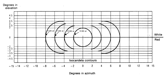
Figure 9.9‑4: Light intensity distribution of PAPI
Notes: 1. These curves are for minimum intensities in red light. 2. The intensity value in the white sector of the beam is no less than 2 and may be as high as 6.5 times the corresponding intensity in the red sector. |
9.9.4.7 Approach slope and elevation setting of light units. The requirements for the approach slope and elevation setting of light units are:
(a) The approach slope, as defined in Figure 9.9‑5, must be appropriate for use by the aeroplanes using the approach. The standard approach slope is 3°.
(b) When the runway on which a PAPI is provided is equipped with an ILS, the siting and elevation of the light units must be such that the PAPI approach slope conforms as closely as possible with the ILS glide path.
(c) The angle of elevation settings of the light units in a PAPI wing bar must be such that, during an approach, the pilot of an aeroplane observing a signal of one white and three reds will clear all objects in the approach area by a safe margin. See 9.9.2.4(a) concerning the raising of the approach slope.
(d) The azimuth spread of the light beam must be suitably restricted where an object located outside the obstacle assessment surface of the PAPI system, but within the lateral limits of its light beam, is found to extend above the plane of the obstacle assessment surface and an aeronautical study indicates that the object could adversely affect the safety of operations. The extent of the restriction must be such that the object remains outside the confines of the light beam.
(e) Where a double-sided PAPI is provided, corresponding units must be seen at the same angle so that the signals of each wing bar change symmetrically at the same time.

Figure 9.9‑5: Light beams and angle of elevation setting for PAPI 3° approach slope
9.9.4.8 Determining PAPI wing bar distance from threshold
(a) The optimum distance of PAPI wing bar from the runway threshold is determined by:
(i) the requirement to provide adequate wheel clearance over the threshold for all types of aircraft landing on the runway;
(ii) the operational desirability that PAPI is compatible with any non-visual glide path down to the minimum possible range and height; and
(iii) any difference in elevation between the PAPI units and the runway threshold.
(b) The distance of the PAPI units from the threshold may have to be modified from the optimum after consideration of:
(i) the remaining length of runway available for stopping the aircraft; and
(ii) obstacle clearance.
(c) Table 9.9‑4 specifies the standard wheel clearance over the threshold for the most demanding amongst the aircraft regularly using the runway, for four aircraft eye-to-wheel height groups. Where practicable, the standard wheel clearance shown in column (2) must be provided.
(d) Where the landing run may be limited, especially at smaller aerodromes, a reduction in wheel clearance over the threshold may be more acceptable than a loss of landing distance. The special minimum wheel clearance shown in column (3) may be used in such a situation, if an aeronautical study indicates such reduced clearances to be acceptable. As guidance, these wheel clearances are unlikely to be acceptable where there are objects under the approach near the threshold, such as approach light supporting structures, boundary fences, roads, etc.
(e) The final location of the units is determined by the relationship between the approach angle, the difference in levels between threshold and the units, and the minimum eye height over the threshold (MEHT). The angle M used to establish the MEHT is 2’ of arc less than the setting angle of the unit which defines the lower boundary of the on-slope indication, i.e. unit B, the third unit from the runway. See Figure 9.9‑6.
(f) Where a PAPI is installed on a runway not equipped with an ILS, the distance D1 shall be calculated to ensure that the lowest height at which a pilot will see a correct approach path indication provides the wheel clearance over the threshold specified in Table 9.9‑4 for the most demanding amongst aeroplanes regularly using the runway.
(g) Where a PAPI is installed on a runway equipped with an ILS, the distance D1 shall be calculated to provide the optimum compatibility between the visual and non-visual aids for the range of eye-to-antenna heights of the aeroplanes regularly using the runway.
(h) If a wheel clearance greater than that that specified in 9.9.4.8(f) is required for specific aircraft, this can be achieved by increasing D1.
(i) Distance D1 shall be adjusted to compensate for differences in elevation between the lens centres of the light units and the threshold.
(j) PAPI units must be the minimum practicable height above ground, and not normally more than 0.9 m. All units of a wing bar should ideally lie in the same horizontal plane; however, to allow for any transverse slope, small height differences of no more than 50 mm between light units are acceptable. A lateral gradient not greater than 1.25% can be accepted provided it is uniformly applied across the units.
Table 9.9‑4: Wheel clearance over threshold for PAPI
Eye-to-wheel height of aeroplane in the approach configuration a | Standard wheel clearance
(metres)b | Special minimum wheel clearance
(metres)c, d |
(1) | (2) | (3) |
Up to but not including 3 m | 6 | 3 |
3 m up to but not including 5 m | 9 | 4 |
5 m up to but not including 8 m | 9 | 5 |
8 m up to but not including 14 m | 9 | 6 |
a In selecting the eye-to-wheel height group, only aeroplanes meant to use the system on a regular basis shall be considered. The most demanding amongst such aeroplanes shall determine the eye-to-wheel height group. b Where practicable, the standard wheel clearance shown in column (2) shall be provided. c The wheel clearance may be reduced to not less than those in column (3) with specific agreement of CASA, where an aeronautical study indicates that such reduced wheel clearances are acceptable. d Where the Special Minimum wheel clearance is provided at a displaced threshold it shall be ensured that the corresponding Standard wheel clearance specified in column (2) will be available when an aeroplane at the top end of the eye-to-wheel height group chosen overflies the extremity of the runway. |
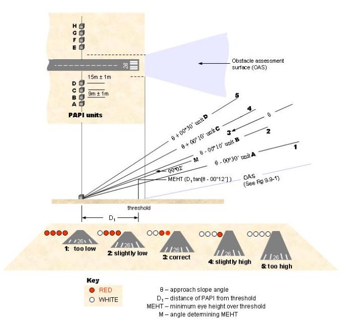
Figure 9.9‑6: The arrangement of a PAPI system and the resulting display
9.9.4.9 Procedure for Establishing the Distance of the PAPI Wing Bar from the Runway Threshold
(a) Decide on the required approach slope. The standard approach slope is 3°.
(b) On runways where no ILS is installed, refer to Table 9.9‑4 to determine the aeroplane eye-to-wheel group and the wheel clearance to be provided at the threshold. The MEHT, which provides the appropriate wheel clearance over the threshold, is established by adding the approach configuration eye-to-wheel height of the most demanding amongst the aircraft regularly using the runway to the required threshold wheel clearance.
(c) The calculation of the nominal position of the PAPI is made on the assumption that the PAPI units are at the same level as the runway centreline adjacent to them, and this level, in turn, is the same as that of the runway threshold. The nominal distance of the PAPI is derived by multiplying the required MEHT by the cotangent of the angle M in Figure 9.9‑6.
(d) Where there is a difference in excess of 0.3 m between the elevation of the runway threshold and the elevation of unit B at the nominal distance from the threshold, it will be necessary to displace the PAPI from its nominal position. The distance will be increased if the proposed site is lower than the threshold and will be decreased if it is higher. The required displacement is determined by multiplying the difference in level by the cotangent of the angle M.
(e) Where a PAPI is installed on a runway equipped with an ILS, the distance D1 must be equal to that between the threshold and the effective origin of the ILS glide path, plus a correction factor for the variation of eye-to-antenna heights of the aeroplanes concerned. The correction factor is obtained by multiplying the average eye-to-antenna height of those aeroplanes by the cotangent of the approach angle. The PAPI is then aimed at the same angle as the ILS glide slope. Harmonization of the PAPI signal and the ILS glide path to a point closer to the threshold may be achieved by increasing the width of the PAPI on-course sector from 20' to 30'. However, the distance D1 must be such that in no case will the wheel clearance over the threshold be lower than specified in column (3) of Table 9.9‑4.
9.10.1.1 A runway edge lighting system may be of the following type:
(a) low intensity – a single intensity lighting system suitable for a non-instrument runway or a non-precision approach runway. This is provided at an aerodrome where there is no appropriate person, such as an air traffic controller, certified air/ground radio operator, or similar, to adjust the intensity settings of the lights;
(b) medium intensity – a 3-stage intensity lighting system suitable for a non-instrument runway or a non-precision approach runway. This is provided to enhance the lighting system particularly in marginal weather conditions. This system cannot be used at an aerodrome that does not have air traffic services or similar personnel.
Note: This requirement is for controlling light intensity during the landing phase. This section is not to be confused with lighting systems controlled by a photo-electric cell which can provide Day, Twilight and Night intensity settings based on ambient conditions. |
(c) high intensity – a 5 or 6 stage intensity lighting system which is suitable for precision approach runways. This system cannot be used at an aerodrome that does not have air traffic services or similar personnel.
9.10.2.1 Runway edge lights must be provided for a runway intended for use at night or for a precision approach runway intended for use by day or night.
9.10.2.2 Runway edge lighting must meet the following operational requirements:
(a) for every runway intended for use at night, omnidirectional lights meeting the characteristics requirements of 9.10.6 shall be provided to cater for both visual circling after an instrument approach to circling minima, and circuits in VMC;
(b) for a precision approach runway, in addition to (a) above, unidirectional lights meeting the characteristics requirements of 9.10.7, and 9.10.8, if applicable, shall also be provided.
Note: Successful past practice has been for separate light fittings, one to satisfy the omnidirectional characteristic, and another to satisfy the unidirectional characteristic, to be provided. |
9.10.3.1 Runway edge lights must be placed along both sides of the runway, in two parallel straight rows equidistant from the centreline of the runway, commencing one-light spacing from the threshold and continuing to one-light spacing from the runway end.
9.10.4.1 The longitudinal spacing of runway edge lights must be uniform and be:
(a) for an instrument runway, 60 m +0 / -5 m;
(b) for a non-instrument runway, 90 m ± 10 m, or 60 m +0 / -5 m if there is an intention to upgrade the runway to an instrument runway at some time in the future.
(c) for non-precision instrument runways intended to be used in visibility conditions of 1.5 km or greater, where existing edge lights are spaced at 90 m ±10 m, it is acceptable to retain this spacing until the next replacement or improvement of the edge lighting system. (This situation typically arises from an existing non-instrument runway being upgraded to a non-precision instrument runway, but without re-installing the runway edge lights to the 60 m +0 / -5 m standard.)
Notes: 1. With GPS technology, virtually any runway can become an instrument runway. Accordingly, it is recommended that any new runway edge lights should be spaced in accordance with Paragraph 9.10.4.1(a). 2. Existing lights spaced in accordance with previous standards of 200 ft or 300 ft imperial measurements may exceed 60 m or 100 m respectively. They are deemed to comply with the standards of this Paragraph, until the next replacement or upgrade of the edge lighting system. |
9.10.4.2 Where the runway is a non-instrument or a non-precision instrument runway, and it is intersected by other runways or taxiways:
(a) within 600 m of the threshold, lights may be spaced irregularly, but not omitted, and
(b) more than 600 m from the threshold, lights may be spaced irregularly or omitted, but no two consecutive lights may be omitted;
provided that such irregular spacing or omission does not significantly alter the visual guidance available to a pilot using the runway.
9.10.4.3 Runway edge lights must not to be omitted on a precision approach runway.
9.10.4.4 Where a runway edge light cannot be omitted, inset runway edge lights must be provided in place of elevated lights.
9.10.4.5 Unless a light is omitted or displaced in accordance with Paragraph 9.10.4.2, a runway edge light must be aligned with a light on the opposite side of the runway.
9.10.5.1 Subject to Paragraph 9.10.5.2, runway edge lights must be placed along the edges of the area declared for use as the runway or outside the edges of the area at a distance of not more than 3 m.
Note: Existing edge lights located beyond 3 m from the edge of runway as a result of a reduction in the declared runway width do not need to be relocated until they are being replaced. |
9.10.5.2 If the width of a runway is less than 30 m in width, the runway edge lights must be placed as if the runway is 30 m in width, and in accordance with Paragraph 9.10.5.1.
9.10.5.3 If a runway is provided with both low or medium intensity and high intensity runway light units, the row of high intensity light units shall be placed closer to the runway centreline. The two rows of light units are to be parallel, separated by a distance of at least 0.5 m.
9.10.6.1 Low intensity and medium intensity runway edge lights must be fixed omnidirectional lights that show variable white. Elevated omnidirectional lights must have light distribution that is uniform for the full 360° horizontal coverage. Where elevated lights are impracticable and inset lights are used, the photometric characteristics of the inset lights are to be as close as practicable to those of the elevated lights.
9.10.6.2 The minimum light intensity for low intensity runway edge lights is to be in accordance with Section 9.11, Figure 9.11‑1. The main beam, between 0º and 7º above the horizontal, is to have a minimum average intensity of not less than 100 cd, and a maximum average intensity of not more than 200 cd.
9.10.6.3 Low intensity runway edge lights are to have a single intensity for all lights in the same runway lighting system.
9.10.6.4 The minimum light intensity for medium intensity runway edge lights is to be in accordance with Section 9.11, Figure 9.11‑2. The main beam, between 0º and 7º above the horizontal, is to have a minimum average intensity of not less than 200 cd, and a maximum average intensity of not more than 600 cd.
9.10.7.1 High intensity runway edge lights must be fixed unidirectional lights with the main beam directed towards the threshold.
9.10.7.2 High intensity runway edge light beam coverage shall be toed in towards the runway as follows:
(a) 3.5° in the case of a 30-45 m wide runway;
(b) 4.5° in the case of a 60 m wide runway.
9.10.7.3 High intensity runway edge lights must show variable white except for those located within 600 m from the runway end which must show yellow.
9.10.7.4 The minimum light intensity for high intensity runway edge lights that show variable white is to be in accordance with Section 9.11
(a) Figure 9.11‑3 for 30 m to 45 m wide runways; and
(b) Figure 9.11‑4 for 60 m wide runways.
9.10.7.5 The minimum light intensity for high intensity runway edge lights that show yellow is the standard set out in Figure 9.11‑3 or Figure 9.11‑4, whichever is applicable, multiplied by 0.4.
9.10.8.1 On a runway where high intensity edge lights are intended to be used from either direction, separate high intensity runway edge light fittings may be provided back-to-back, or bidirectional light fittings with the correct toe-in angle built in, may be used.
9.10.9.1 Runway threshold lights must be provided on a runway that is equipped with runway edge lights.
9.10.10.1 Runway threshold lights must be located in a straight line at right angles to the centreline of the runway and:
(a) when the threshold is at the extremity of a runway – as near to the extremity as possible and not more than 3 m outside, or 1 m inside of the extremity; or
(b) when the threshold is a displaced threshold – at the displaced threshold with a tolerance of ± 1 m.
9.10.11.1 Low and medium intensity runway threshold lights are to consist of:
(a) 2 omnidirectional lights, one at each end of the threshold and in line with the runway edge lights; and
(b) 6 unidirectional lights at equal intervals between the 2 omnidirectional lights.
9.10.11.2 The 6 unidirectional lights are to be inset lights if:
(a) the threshold is a permanently displaced threshold; or
(b) the threshold is also equipped with high intensity threshold lights; or
(c) it is impractical for elevated lights to be installed.
9.10.11.3 Subject to paragraph 9.10.11.6, only an aerodrome used predominantly for training and general aviation may use the alternative pattern of low intensity or medium intensity runway threshold lights as described in paragraph 9.10.11.5.
9.10.11.4 The alternative pattern is not suitable for aerodromes used predominantly by aircraft having a take-off weight greater than 5,700 kg, nor is it suitable for aerodromes where commercial air transport jet propelled aeroplanes operate.
9.10.11.5 The alternative pattern consists of:
(a) 6 elevated lights arranged in 2 groups of 3 equally spaced lights, with the distance between the 2 groups equal to half the lateral distance between the 2 rows of runway edge lights; and.
(b) The outer lights on either side shall be omnidirectional green lights, and the inner 4 lights shall be unidirectional green lights (or bidirectional green/red lights when the same light fittings are used for runway end lights).
9.10.11.6 On and after 1 June 2010, an aerodrome may use the alternative pattern of low intensity or medium intensity runway threshold lights in paragraph 9.10.11.5 only if:
(a) the aerodrome was using, and was entitled to use, the alternative pattern immediately before 1 June 2010; and
(b) the aerodrome operator continues to comply with the alternative pattern on and after that date.
9.10.12.1 High intensity runway threshold lights must consist of:
(a) 2 unidirectional lights, one at each end of the threshold and in line with the row of runway edge lights; and
(b) unidirectional lights uniformly spaced between the 2 outer lights, at intervals of not more than 3 m. These lights must be inset lights.
9.10.13.1 Low intensity and medium intensity runway threshold lights must have the following characteristics:
(a) the outermost light on each side must be a fixed omnidirectional light showing green;
(b) the inner lights must be fixed unidirectional lights showing green in the direction of approach over not less than 38° or more than 180° of azimuth;
(c) the light distribution in the direction of approach must be as close as practicable to that of the runway edge lights;
(d) the intensity of the green lights must be in the range of 1 to 1.5 times the intensity of the runway edge lights.
Note: Older installations with the intensity of green light in the range of 0.5 to 1 times the intensity of the runway edge lights are acceptable, until the next replacement or upgrade of the runway and/or threshold lighting system. |
9.10.14.1 High intensity runway threshold lights must be fixed lights showing green in the direction of approach with a minimum light intensity in accordance with Section 9.11, Figure 9.11‑5.
9.10.15.1 Threshold Wing Bars:
(a) On a precision approach runway, if it is operationally required that an increase in the conspicuity of the threshold at night be provided, the threshold may be provided with threshold wing bars.
(b) Where provided, threshold wing bars must be symmetrically disposed on either side of the threshold:
(i) each wing bar is to consist of 5 lights at 2.5 m apart;
(ii) at right angles to the runway centreline; and
(iii) with the inner most light of each wing bar aligned with the row of runway edge lights on that side of the threshold.
9.10.15.2 Characteristics of Threshold Wing Bars:
(a) Threshold wing bars must have the following characteristics:
(i) be fixed unidirectional lights showing green in the direction of approach; and
(ii) the minimum light intensity is to be in accordance with Section 9.11, Figure 9.11‑6.
(b) If it is impracticable to use elevated lights, inset lights may be used, however, inset and elevated lights must not be used in the same threshold wing bar.
9.10.15.3 Runway Threshold Identification Lights:
(a) At an aerodrome where it is difficult to locate a runway threshold from the air during the day such as in the case of a displaced threshold or an aerodrome with complex runway/taxiway layout in the vicinity of the threshold, runway threshold identification lights may be required.
Note: Runway threshold identification lights may also assist pilot acquisition of a threshold during twilight hours and at night. During these periods the lights need to be controlled such that an approaching pilot will not be dazzled by the flashing lights. |
(b) Runway threshold identification lights must be provided, during the day, to mark a temporarily displaced threshold of a runway serving international jet propelled aeroplanes conducting air transport operations.
Note: Runway threshold identification lights may also be used to mark the temporarily displaced thresholds of other runways. When used, the need for temporarily displaced threshold V‑bar markings is normally waived. |
9.10.15.4 Location of runway threshold identification lights. Because of their nature and use, runway threshold identification lights can have more flexibility in their installation location than other visual aids. Advantage can be taken of this particularly when they are provided on temporary displaced thresholds, to site them clear of existing facilities, and works areas.
9.10.15.5 Where provided, one light unit shall be on each side of the runway, equidistant from the runway centreline, on a line perpendicular to the runway centreline. The optimum location of the light units shall be 12 to 15 m outside each line of runway edge lights, and in line with the threshold. The light units may be located laterally up to 20 m from the line of runway edge lights and longitudinally up to 12 m prior to the threshold. Each light unit shall be a minimum of 12 m from the edge of taxiways and runways. The elevation of both light units shall be within 1 m of a horizontal plane through the runway centreline, with the maximum height above ground not exceeding 1 m.
9.10.15.6 Characteristics of runway threshold identification lights. Runway threshold identification lights must have the following characteristics:
(a) be flashing lights;
(b) the light flashes are synchronised with a normal flash rate of 100-120 per minute;
(c) the colour of the lights is white;
(d) a minimum range in bright sunlight of approximately 7 km; and
(e) the beam axis of each light unit shall be aimed 15° outward from a line parallel to the runway centreline and inclined at an angle of 10° above the horizontal.
Note: L-849 A and E light units specified in FAA AC 150/5345-51 ‘Specification for Discharged -Type of Flashing Light Equipment’ are xenon strobe type of lights suitable for use as runway threshold identification lights. |
9.10.15.7 Temporarily displaced threshold lights for use at night. Temporarily displaced threshold lights must be provided at night to identify the new threshold location when the threshold of a runway is temporarily displaced.
9.10.15.8 Location of temporarily displaced threshold lights. Temporarily displaced threshold lights must be provided on each side of the runway:
(a) in line with the displaced threshold:
(b) at right angles to the runway centreline; and
(c) with the innermost light on each side aligned with the row of runway edge lights on that side of the threshold.
9.10.15.9 Characteristics of temporarily displaced threshold lights. Temporarily displaced threshold lights must have the following characteristics:
(a) each side must consist of 5 lights except that 3 lights per side is sufficient if the runway width is 30 m or less;
(b) the lights must be spaced at 2.5 m apart;
(c) the innermost light of each side must be a fixed omnidirectional light showing green in all angles of azimuth;
(d) the outer 4 or 2 lights, as appropriate, of each side must be fixed unidirectional lights showing green in the direction of approach, over not less than 38° or more than 180° of azimuth;
(e) the light distribution in the direction of approach must be as close as practicable to that of the runway edge lights;
(f) the light intensity must be as close as practicable to 1.5 times, and not less than, that of the runway edge lights.
Note: Temporary displaced threshold lights are associated only with low intensity or medium intensity runway lighting systems. They are not associated with high intensity runway lighting systems. If a precision approach runway has the threshold temporarily displaced, it renders ILS unavailable for precision approaches, which changes the runway to a non-precision or non-instrument runway. |
9.10.15.10 Runway lighting before a displaced threshold
(a) If the part of runway located before a displaced threshold is available for aircraft use, i.e. for take-offs, and landings from the opposite direction, runway edge lights in this part of runway must:
(i) show red in the direction of approach to the displaced threshold; and
(ii) show white in the opposite direction, or yellow as appropriate for a precision approach runway.
(b) The intensity of the red runway edge lights required under Paragraph 9.10.15.10(a) must not be less than one-quarter, and not more than one-half, that of the white runway edge lights.
(c) Runway edge lights may be bidirectional light fittings or separate light fittings installed back to back.
(d) If the portion of runway before a displaced threshold is closed to aircraft operations, all the runway lights thereon must be extinguished.
9.10.16.1 Runway end lights must be provided on a runway equipped with runway edge lights.
9.10.17.1 Runway end lights must be located in a straight line at right angles to the runway centreline, and:
(a) when the runway end is at the extremity of the runway – as near to the extremity as possible and not more than 3 m outside, or 1 m inside the extremity;
(b) when the runway end is not at the extremity of the runway – at the runway end, with a tolerance of ± 1 m.
(c) for the following areas:
(i) a taxiway for exiting a runway;
(ii) a runway turning area;
(iii) other similar areas;
the runway end lights must be located in such a way that an aircraft using the area will not be required to cross the row of red lights comprising the runway end lights.
Note: The universally accepted convention in aerodrome lighting is that a pilot is never required to cross a row of red lights. |
9.10.18.1 The pattern of runway end lights must consist of:
(a) at least 6 lights spaced at equal intervals between the rows of runway edge lights; or
(b) if the runway is provided with the alternative threshold light pattern, the threshold pattern.
9.10.18.2 For a precision approach runway Category III, the spacing between runway end lights must not exceed 6 m.
9.10.19.1 Low intensity and medium intensity runway end lights must have the following characteristics:
(a) the lights must be fixed unidirectional showing red in the direction of the runway over not less than 38° or more than 180° of azimuth;
(b) the intensity of the red light must not be less than one-quarter, and not more than one-half, that of the runway edge lights;
(c) the light distribution in the direction of the runway must be as close as practicable to that of the runway edge lights.
9.10.19.2 Low intensity and medium intensity runway end lights must be inset lights if:
(a) the runway is also equipped with high intensity runway end lights; or
(b) it is impracticable for elevated lights to be installed.
9.10.19.3 If the runway end coincides with the runway threshold, bidirectional light fittings may be used or separate light fittings installed back to back.
9.10.20.1 High intensity runway end lights must have the following characteristics:
(a) the lights must be inset, fixed unidirectional showing red in the direction of the runway; and
(b) the minimum light intensity must be in accordance with Section 9.11, Figure 9.11‑7.
9.10.21.1 Where an aircraft turning area is provided on a runway, the edge of the turning area must be provided with blue edge lights if the runway is provided with edge lights.
9.10.21.2 Runway turning area edge lights must be located not less than 0.6 m, and not more than 1.8 m, outside the edge of the turning area.
9.10.21.3 If the beginning of the splay into a runway turning area is more than 10 m from the previous runway edge light, a blue edge light must be located where the turning area commences.
9.10.21.4 Turning area edge lights must be provided to mark any change of direction along the side of the turning area.
9.10.21.5 Where a side of the turning area is longer than 30 m, equally spaced blue edge lights must be provided along that side, with spacing not exceeding 30 m.
9.10.21.6 Runway turning area edge lights must have the same characteristics as taxiway edge lights, in accordance with Paragraph 9.13.15.
9.10.22.1 Stopway lights must be provided on a stopway which is longer than 180 m and is intended for night use.
9.10.22.2 Stopway lights must be located along both sides of the stopway in line with the runway edge lights and up to the stopway end.
9.10.22.3 The spacing of stopway lights must be uniform and not more than that of the runway edge lights, with the last pair of lights located at the stopway end.
9.10.22.4 The stopway end must be further indicated by at least 2 stopway lights at equal intervals across the stopway end between the last pair of stopway lights.
9.10.22.5 Stopway lights must have the following characteristics:
(a) the lights must be fixed and unidirectional showing red in the direction of the runway, and not visible to a pilot approaching to land over the stopway;
(b) the light distribution in the direction of the runway must be as close as possible to that of the runway edge lights; and
(c) the intensity of the red light must not be less than one quarter, and not more than one half, that of the white runway edge lights.
9.10.23.1 Hold short lights must be provided on a runway which is intended to accommodate land and hold short operations (LAHSO).
9.10.23.2 Hold short lights must be at least 6 inset lights located across the runway as near to the hold short line as possible, and in any case not beyond, and not more than 3 m before the hold short line, which is at least 75 m from the centreline of the intersecting runway.
9.10.23.3 The hold short lights must be at right angles to the runway, and located symmetrically about the runway centreline, with the closest lights at 1.5 m from the centreline, and subsequent lights 3 m apart.
9.10.23.4 The hold short lights must be unidirectional, showing white in the direction of approach to the hold short position, and have photometric characteristics in accordance with Section 9.11, Figure 9.11‑8.
9.10.23.5 The lights must occult, in unison, at between 25 and 35 cycles per minute. The illumination period shall be approximately 2/3, and the light suppression period shall be approximately 1/3, of the total period of each cycle.
Note: The illumination and suppression period will be affected by varying the light intensity. The FAA AC 150/5345-54 specified L-884 Power and Control Unit (PCU) is typically used to power LAHSO systems. The PCU pulses the lights by varying the voltage on the primary side of the series circuit. The light fixtures need to be isolated from the series circuit via 6.6/6.6 ampere isolating transformers. Typically, the PCU continuously switches the output current with an ‘on’ cycle duration of 1.35 ± 0.1 seconds, and an ‘off’ cycle duration of 0.8 ± 0.1 seconds. |
9.10.23.6 Each bar of hold short lights must be individually controlled, provided with variable intensity setting, and technically monitored for serviceability, at the operator position of the ATC operator controlling the LAHSO operation.
9.10.23.7 Where secondary power is available, hold short lights must be connected to that power system, with changeover times not greater than for the runway lighting on the same runway.
9.10.24.1 Runway centreline lights must be provided on the following:
(a) a Cat II or III precision approach runway;
(b) a runway intended for take-offs with an operating minimum below an RVR of 350 m.
Note: Runway centreline lights are also recommended for the following runways if the distance between the runway edge lights is greater than 50 m: (a) Cat I precision approach runways; (b) runways intended for take-offs with an operating minimum equal to or above an RVR of 350 m. |
9.10.24.2 Runway centreline lights must be located from the threshold to the end at longitudinal spacing of approximately:
(a) 15 m on a runway intended for use in runway visual range conditions less than a value of 350 m; and
(b) 30 m on a runway intended for use in runway visual range conditions of 350 m or greater.
9.10.24.3 The runway centreline lights may be offset by not more than 0.6 m from the true runway centreline, for maintenance of runway marking purposes.
9.10.24.4 The offset shall be on the left hand side of the landing aircraft, where practicable. Where the runway is used in both directions, the direction from which the majority of landings will take place shall prevail.
9.10.24.5 Runway centreline lights must be inset, fixed lights showing white from the threshold to a point 900 m from the runway end. From 900 m to 300 m from the runway end, the light pattern is to be two red lights followed by two white lights. For the last 300 m before the runway end, the lights must show red.
Note: The double red and white alternating light arrangement is for interleaving circuitry, to ensure that failure of part of the electrical system does not result in a false indication of the runway distance remaining. |
9.10.24.6 The light intensity and distribution of runway centreline lights must be in accordance with:
(a) Section 9.11, Figure 9.11‑8 — for 30 m spacing;
(b) Section 9.11, Figure 9.11‑9 — for 15 m spacing.
9.10.25.1 Runway touchdown zone lights must be provided for a runway intended for precision approach Category II or III operations.
Note: Where a precision approach Category II or Category III lighting system is provided, touchdown zone lights must also be provided. |
9.10.25.3 Runway touchdown zone lights must extend from the threshold for a distance of 900 m. The lighting is to consist of a series of transverse rows of lights, or barrettes, symmetrically located on each side of the runway centreline.
9.10.25.4 Each barrette must consist of three light units at 1.5 m apart. The innermost light of each barrette must be at 9 m from the true runway centreline.
9.10.25.5 The first pair of barrettes must be located at 60 m from the threshold. Subsequent barrettes must be spaced longitudinally at 60 m apart.
9.10.25.6 Runway touchdown zone lights must be inset, fixed unidirectional lights showing variable white.
9.10.25.7 Runway touchdown zone lights must be in accordance with Section 9.11, Figure 9.11‑10.
9.10.26.1 Section 9.11, Figure 9.11‑11 shows the method of establishing the grid points for calculating the average intensity of low and medium intensity runway lights for non-instrument and instrument non-precision approach runways.
9.10.26.2 Section 9.11, Figure 9.11‑12 shows the method of establishing grid points for calculating the average intensity of high intensity approach and runway lights for precision approach runways.
9.10.26.3 The average light intensity of the main beam of a light is calculated by:
(a) establishing grid points in accordance with the method shown in Section 9.11, Figure 9.11‑11 or Figure 9.11‑12, whichever is applicable.
(b) measuring the light intensity values at all grid points within and on the perimeter of the rectangle or ellipse representing the main beam;
(c) calculating the arithmetic average of the light intensity values as measured at those grid points.
9.10.26.4 The maximum light intensity value measured on or within the perimeter of the main beam must not to be more than three times the minimum light intensity value so measured.
9.10.27.1 The following points must be followed in the installation and aiming of light fittings:
(a) the lights are aimed so that there are no deviations in the main beam pattern, to within 1/2° from the applicable standard specified in this Chapter;
(b) horizontal angles are measured with respect to the vertical plane through the runway centreline;
(c) when measuring horizontal angles for lights other than runway centreline lights, the direction towards the runway centreline is to be taken to be positive;
(d) vertical angles specified are to be measured with respect to the horizontal plane.
9.10.28.1 Section 9.12 contains illustrations of runway lighting.
9.11.1.1 The ellipses in each figure are symmetrical about the common vertical and horizontal axes.
9.11.1.2 Figure 9.11‑1 to Figure 9.11‑10 show the minimum allowable light intensities. The average intensity of the main beam is calculated by establishing the grid points as shown in Figure 9.11‑11 or Figure 9.11‑12, as appropriate, and using the intensity values measured at all grid points located within and on the perimeter of the ellipse representing the main beam. The average value is the arithmetic average of light intensities measured at all considered grid points.
9.11.1.3 No deviations are acceptable in the main beam pattern when the lighting fixture is properly aimed.
9.11.1.4 Average intensity ratio. The ratio between the average intensity within the ellipse defining the main beam of a typical new light and average light intensity of the main beam of a new runway edge light is to be as follows:
Figure 9.11‑1 | Low intensity runway edge lights | 1.0 (white light) |
Figure 9.11‑2 | Medium intensity runway edge lights | 1.0 (white light) |
Figure 9.11‑3 | High intensity runway edge lights (where the width of runway is 30-45 m) | 1.0 (white light) |
Figure 9.11‑4 | High intensity runway edge lights (where the width of runway is 60 m) | 1.0 (white light) |
Figure 9.11‑5 | High intensity threshold lights | 1.0 to 1.5 (green light) |
Figure 9.11‑6 | High intensity threshold wing bar lights | 1.0 to 1.5 (green light) |
Figure 9.11‑7 | High intensity runway end lights | 0.25 to 0.5 (red light) |
Figure 9.11‑8 | High intensity runway centreline lights (longitudinal spacing 30 m) | 0.5 to 1.0 (white light) |
Figure 9.11‑9 | High intensity runway centreline lights (longitudinal spacing 15 m) | 0.5 to 1.0 for CAT III (white light)
0.25 to 0.5 for CAT I, II (white light) |
Figure 9.11‑10 | Runway touchdown zone lights | 0.5 to 1.0 (white light) |
9.11.1.5 The beam coverages in the figures provide the necessary guidance for approaches down to an RVR of the order of 150 m and take-off to an RVR of the order of 100 m.
9.11.1.6 Horizontal angles are measured with respect to the vertical plane through the runway centreline. For lights other than centreline lights, the direction towards the runway centreline is considered positive. Vertical angles are measured with respect to the horizontal plane.
9.11.1.7 The light units are to be installed so that the main beam is aligned within one-half degree of the specified requirement.
9.11.1.8 On the perimeter of and within the ellipse defining the main beam, the maximum light intensity is not to be greater than three times the minimum light intensity value measured.

Figure 9.11‑1: Isocandela Diagram for Omnidirectional Runway Edge Light - Low Intensity Runway Lighting System
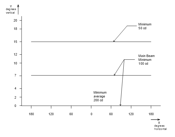
Figure 9.11‑2: Isocandela Diagram for Omnidirectional Runway Edge Light - Medium Intensity Runway Lighting System

Figure 9.11‑3: Isocandela Diagram for High Intensity Runway Edge Lights where the Width of the Runway is 30 to 45 metres (White Light)
Notes: 1. Curves calculated on formula
2. Toe-in 3.5º
3. For yellow light multiply values by 0.4
4. See collective notes at Paragraph 9.11.1 for Figure 9.11‑1 to Figure 9.11‑10.
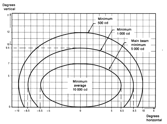
Figure 9.11‑4: Isocandela Diagram for High Intensity Runway Edge Lights where the Width of the Runway is 60 m (White Light)
Notes: 1. Curves calculated on formula
2. Toe-in 4.5º
3. For yellow light multiply values by 0.4
4. See collective notes at Paragraph 9.11.1 for Figure 9.11‑1 to Figure 9.11‑10.
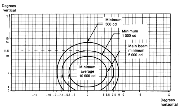
Figure 9.11‑5: Isocandela Diagram for High Intensity Threshold Lights (Green Light)
Notes: 1. Curves calculated on formula
2. Toe-in 3.5º
3. See collective notes at Paragraph 9.11.1 for Figure 9.11‑1 to Figure 9.11‑10.
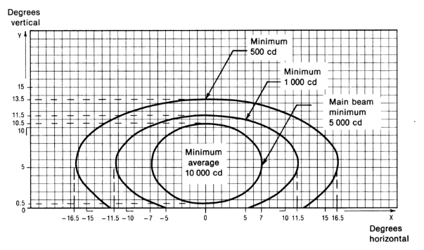
Figure 9.11‑6: Isocandela Diagram for High Intensity Threshold Wing Bar Lights (Green Light)
Notes: 1. Curves calculated on formula
2. Toe-in 2º
3. See collective notes at Paragraph 9.11.1 for Figure 9.11‑1 to Figure 9.11‑10.
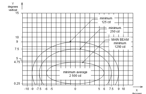
Figure 9.11‑7: Isocandela Diagram for High Intensity Runway End Lights (Red Light)
Notes: 1. Curves calculated on formula
2. See collective notes at Paragraph 9.11.1 for Figure 9.11‑1 to Figure 9.11‑10.

Figure 9.11‑8: Isocandela Diagram for High Intensity Runway Centreline Lights with 30 m Longitudinal Spacing (White Light)
Notes: 1. Curves calculated on formula
2. For red light multiply values by 0.15
3. See collective notes at Paragraph 9.11.1 for Figure 9.11‑1 to Figure 9.11‑10.

Figure 9.11‑9: Isocandela Diagram for High Intensity Runway Centreline Lights with 15 m Longitudinal Spacing (White Light)
Notes: 1. Curves calculated on formula
2. For red light multiply values by 0.15
3. See collective notes at Paragraph 9.11.1 for Figure 9.11‑1 to Figure 9.11‑10.

Figure 9.11‑10: Isocandela Diagram for Runway Touchdown Zone Lights (White Light)
Notes: 1. Curves calculated on formula
2. Toe-in 4º
3. See collective notes at Paragraph 9.11.1 for Figure 9.11‑1 to Figure 9.11‑10.

Figure 9.11‑11: Method of Establishing Grid Points to be used for the Calculation of Average Intensity of Runway Lights specified by Figure 9.11‑1 and Figure 9.11‑2

Figure 9.11‑12: Method of Establishing Grid Points to be used for the Calculation of Average Intensity of Runway Lights specified by Figure 9.11-3 to Figure 9.11-10

Figure 9.12‑1: Runway Edge Lights, Threshold Lights and Runway End Lights Low and Medium Intensity for Non-Instrument and Non-Precision Approach Runways

Figure 9.12‑2: Runway Edge Lights High Intensity for Precision Approach Runways
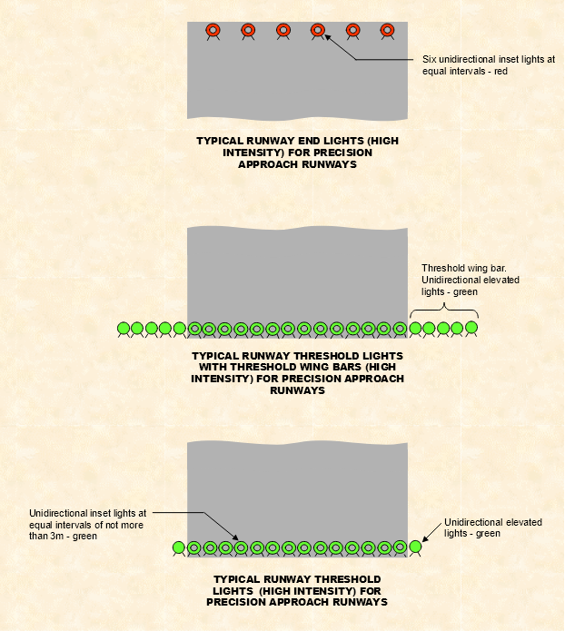
Figure 9.12‑3: Typical Runway Threshold and Runway End Lights High Intensity for Precision Approach Runways
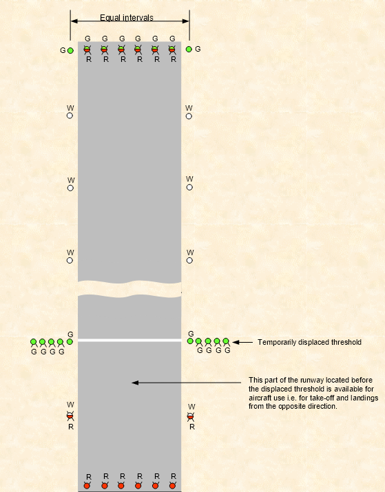
Figure 9.12‑4: Typical Temporarily Displaced Threshold
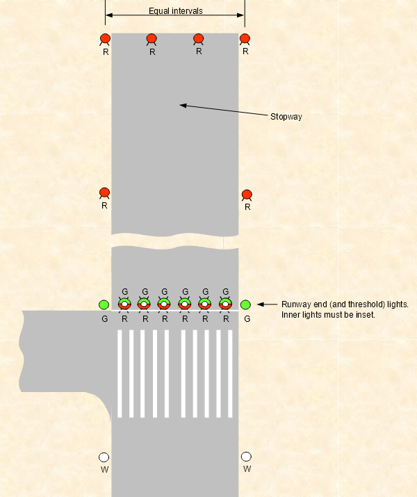
Figure 9.12‑5: Typical Stopway Lights

Figure 9.12‑6: Typical Turning Area Edge Lights

Figure 9.12‑7: Typical Light Layout Where Runway Pavement is 23 m or 18 m wide
9.13.1.1 Unless the aerodrome has light traffic density, a taxiway intended for use in RVR conditions less than a value of 350 m must have centreline lights that provide continuous guidance between the runway centreline and the apron.
9.13.1.2 A taxiway intended for use at night in RVR conditions of between 350 m and 1 200 m must have centreline lights unless the aerodrome has:
(a) a simple layout; or
(b) light traffic density.
9.13.1.3 Taxiway centreline lights must be used on a rapid exit taxiway.
9.13.1.4 Taxiway centreline lights may be used in other cases, if the aerodrome chooses. At aerodromes where the layout is complex, the use of taxiway centreline lights would be beneficial for surface movement.
9.13.2.1 Except for Paragraphs 9.13.3.1 and 9.13.4.1, taxiway edge lights must be provided at the edges of a taxiway and holding bays, intended for use at night and not provided with centreline lights.
9.13.2.2 Where additional visual cues are required to delineate apron edges at night, taxiway edge lights may be used. Examples of where this requirement may occur include, but are not limited to:
(a) aprons where taxi guidelines and aircraft parking position marking are not provided;
(b) aprons where apron floodlighting provides inadequate illumination at the edge of the apron; and
(c) where the edge of the apron is difficult to distinguish from the surrounding area at night.
9.13.3.1 For code letter A or B taxiways, retroreflective taxiway centreline or edge markers may be used instead of taxiway centreline or edge lights, provided at least 1 taxiway from the runway to the apron has taxiway centreline or edge lights.
9.13.3.2 If taxiway centreline lights are not provided, taxiway centreline markers may be used to improve guidance on the taxiway, or to supplement:
(a) taxiway centreline marking; or
(b) taxiway edge markers or taxiway edge lights.
Note: Curves and intersections are examples of where improved guidance or supplementation may be given. |
9.13.3.3 If taxiway edge lights are not provided, taxiway edge markers may be used to improve guidance on the taxiway, or to supplement:
(a) taxiway edge marking; or
(b) taxiway centreline markers or taxiway centreline lights.
Note: Curves, intersections and apron edges are examples of where improved guidance or supplementation may be given. |
9.13.4.1 Taxiway lights are not required for an apron taxiway if the apron taxiway is illuminated by apron floodlighting meeting the standards specified in Section 9.16.
9.13.5.1 As far as practicable, the provision of taxiway lights shall be such that taxying aircraft do not need to alternate between taxiway centreline and edge lights.
9.13.5.2 Where additional guidance is required to delineate taxiway edges, taxiway edge lights may be used to supplement taxiway centreline lights. When provided, taxiway edge lights must comply with Paragraphs 9.13.13 to 9.13.15. This may occur at, but is not limited to:
(a) rapid exit taxiways;
(b) taxiway curves;
(c) intersections;
(d) a narrower section of taxiway.
9.13.6.1 At an aerodrome with Air Traffic Service, taxiway lights with an average intensity within the main beam of more than 20 candela must be provided with intensity control in accordance with Paragraph 9.1.14.6, to allow adjustment of the lighting to suit ambient conditions.
9.13.6.2 If it is desired to illuminate only standard taxi routes during certain period of operations, for example during low visibility operations, the taxiway lighting may be designed to allow taxiways in use to be lit and those not in use to be unlit.
9.13.6.3 Where a runway forming part of a standard taxi-route is provided with runway lighting and taxiway lighting, the lighting systems must be interlocked to preclude the possibility of simultaneous operation of both forms of lighting.
9.13.7.1 Taxiway centreline lights must be located on the centreline of the taxiway or uniformly offset from the taxiway centreline by not more than 0.3 m.
Notes: 1. The longitudinal spacing of centreline lights that will provide satisfactory guidance to pilots on curved sections of taxiway, including exit taxiways and fillets at intersections, is influenced by the width of the light beam from the centreline light fittings. 2. Some taxiway centreline lights were introduced in Australian aerodromes before international standards for them were developed. Since then, international standards have been established, with lights having narrower beam spreads, and higher light intensity. Australia has now adopted the internationally accepted ICAO standards on taxiway centreline lights, recognising that international light manufacturers will be producing lights in compliance with these standards. To provide satisfactory guidance with these light fittings it is necessary to use longitudinal spacing that is less than previously used in Australia, particularly on curved sections. |
3. There is no need to replace existing lights, or change the spacing of existing lights. The longitudinal spacing and photometric specifications herein are meant for all new taxiway centreline lights, and for replacement of existing light fittings with light fittings in compliance with ICAO standards. |
9.13.8.1 Except for Paragraphs 9.13.8.2 and 9.13.9.1, the longitudinal spacing of taxiway centreline lights on a straight section of taxiway must be uniform and be not more than the values specified in Table 9.13‑1 below:
Table 9.13‑1 Maximum spacing on straight sections of taxiway
Type | General | Last 60 m before a runway or apron |
Taxiways intended for use in RVR conditions of 550 m or greater | 60 m | 15 m |
Taxiways intended for use in RVR conditions of less than a value of 550 m but not less than a value of 350 m | 30 m | 15 m |
Taxiways intended for use in RVR conditions of less than a value of 350 m | 15 m | 7.5 m |
9.13.8.2 For the purpose of taxiway centreline lighting, a straight section of taxiway that is less than 181 metres in length is considered a short straight taxiway. Taxiway centreline lights on a short straight section of taxiway must be spaced at uniform intervals of not more than 30 m.
9.13.8.3 For a taxiway entering a runway:
(a) the last taxiway centreline light must be not more than 1 m outside the line of runway edge lights; and
(b) if the taxiway centreline lights continue towards the runway centreline, they must end no closer than 1.2 m from the runway centreline.
9.13.8.4 When a taxiway changes from a straight to a curved section, the taxiway centreline lights must continue on from the preceding straight section at a uniform distance from the outside edge of the taxiway.
9.13.8.5 The longitudinal spacing of taxiway centreline lights on a curved section of taxiway must be uniform and be not more than the values specified in Table 9.13‑2.
Table 9.13‑2: Maximum spacing on curved sections of taxiway
Type | On curve with radius of 400 m or less | On curve with radius greater than 400 m | On straight section before and after the curve |
Taxiways intended for use in RVR conditions of 350 m or greater | 15 m See Note | 30 m | No special requirement. Use same spacing as on the rest of the straight section. |
Taxiways intended for use in RVR conditions of less than a value of 350 m | 7.5 m | 15 m | Same spacing as on the curve is to extend for 60 m before and after the curve |
Note: At a busy or complex taxiway intersection where additional taxiing guidance is desirable, closer light spacing down to 7.5 m should be used. |
9.13.9.1 Taxiway centreline lights on exit taxiways, other than rapid exit taxiways, must:
(a) start at the tangent point on the runway;
(b) have the first light offset 1.2 m from the runway centreline on the taxiway side; and
(c) be spaced at uniform longitudinal intervals of not more than 7.5 m.
9.13.10.1 Taxiway centreline lights on a rapid exit taxiway must:
(a) start at least 60 m before the tangent point;
(b) on that part of taxiway parallel to the runway centreline, be offset 1.2 m from the runway centreline on the taxiway side; and
(c) continue at the same spacing to a point on the centreline of the taxiway at which an aeroplane can be expected to have decelerated to normal taxying speed.
9.13.10.2 Taxiway centreline lights on a rapid exit taxiway must be spaced at uniform longitudinal intervals of not more than 15 m.
9.13.11.1 Taxiway centreline lights are to be inset, fixed lights showing green on:
(a) a taxiway other than an exit taxiway; and
(b) a runway forming part of a standard taxi-route.
9.13.11.2 Taxiway centreline lights on exit taxiways, including rapid exit taxiways, must be inset, fixed lights:
(a) showing green and yellow, alternately, from the point where they begin near the runway centreline, to whichever of the following is furthest from the runway:
(i) the perimeter of the ILS critical and sensitive area;
(ii) the lower edge of the inner transitional surface; and
(b) showing green from that point onwards.
9.13.11.3 When viewed from the runway, the exit taxiway light nearest the perimeter or the lower edge of the inner transitional surface, whichever is further, must show yellow.
9.13.11.4 Where the taxiway centreline lights are used for both runway exit and entry purposes, the colour of the lights viewed by a pilot of an aircraft entering the runway must be green. The colour of the lights viewed by a pilot of an aircraft exiting the runway is to be green and yellow alternately. See Figure 9.15‑1.
9.13.11.5 Where the taxiway centreline lights cross a runway, the colour of the taxiway centreline lights viewed by a pilot of an aircraft entering the runway from the taxiway must be:
(a) green up to the runway centreline; and
(b) alternately green and yellow beyond the runway centreline while exiting on the other side of the runway.
9.13.12.1 The beam dimensions and light distribution of taxiway centreline lights must be such that the lights are visible only to pilots of aircraft on, or in the vicinity of, the taxiway.
9.13.12.2 The light distribution of the green taxiway centreline lights in the vicinity of a threshold must be such as not to cause confusion with the runway threshold lights.
9.13.12.3 On a taxiway intended for use in RVR conditions of 350 m or greater, taxiway centreline lights must comply with the specifications set out in Section 9.14, Figure 9.14-1 or Figure 9.14-2, whichever is applicable.
9.13.12.4 On a taxiway intended for use in RVR conditions of less than a value of 350 m, the taxiway centreline lights must comply with the specifications set out in Section 9.14, Figure 9.14-3, Figure 9.14-4 or Figure 9.14-5, whichever is applicable.
Notes: 1 Light units meeting the intensity standards of Figure 9.14‑3, Figure 9.14‑4 and Figure 9.14‑5, are specifically designed for use in low visibility conditions. For the normal range of visibilities experienced most of the time in Australia, these lights, if operated on maximum intensity, would cause dazzle to pilots. If these lights are installed, it may be necessary to provide additional intensity control stages, or otherwise limit the maximum intensity at which they can be operated. 2 Very high intensity taxiway light units are also available. These lights can have main beam intensities of the order of 1800 cd. These lights are unsuitable for use in Australian conditions. |
9.13.13.1 Taxiway edge lights must be located along both sides of the taxiway, with edge lights along each edge located opposite the corresponding lights along the other edge, except as allowed for in Paragraph 9.13.13.2.
9.13.13.2 A taxiway light may be omitted if it would otherwise have to be located on an intersection with another taxiway or runway.
9.13.13.3 Taxiway edge lights must be located outside the edge of the taxiway, being:
(a) equidistance from the centreline except where asymmetric fillets are provided; and
(b) as close as practicable to 1.2 m from the taxiway edge, but no further than 1.8 m, or nearer than 0.6 m.
9.13.13.4 Where a taxiway intersects with a runway, the last taxiway edge lights should preferably line-up with the line of runway edge lights, and must not encroach beyond the line of runway edge lights into the area outlined by the runway edge lights.
9.13.14.1 Spacing of taxiway edge lights must be in accordance with Figure 9.13‑1 below:

Figure 9.13‑1: Longitudinal Spacing for Taxiway Edge Lights
9.13.14.2 On a curved section of taxiway, the edge lights must be spaced at uniform longitudinal intervals in accordance with Curve A in Figure 9.13‑1 above.
9.13.14.3 On a straight section of taxiway, the edge lights must be spaced at uniform longitudinal intervals, not exceeding 60 m, in accordance with Curve B in Figure 9.13‑1 above.
9.13.14.4 Where a straight section joins a curved section, the longitudinal spacing between taxiway edge lights must be progressively reduced, in accordance with Paragraphs 9.13.14.5 and 9.13.14.6, over not less than 3 spacings before the tangent point.
9.13.14.5 The last spacing between lights on a straight section must be the same as the spacing on the curved section.
9.13.14.6 If the last spacing on the straight section is less than 25 m, the second last spacing on the straight section must be no greater than 25 m.
9.13.14.7 If a straight section of taxiway enters an intersection with another taxiway, a runway or an apron, the longitudinal spacing of the taxiway edge lights must be progressively reduced over not less than 3 spacings, before the tangent point, so that the last and the second last spacings before the tangent point are not more than 15 m and 25 m respectively.
9.13.14.8 The taxiway edge lights must continue around the edge of the curve to the tangent point on the other taxiway, the runway or apron edge.
9.13.14.9 Taxiway edge lights on a holding bay or apron edge are to be spaced at uniform longitudinal intervals not exceeding 60 m, and in accordance with Curve B in Figure 9.13‑1.
9.13.15.1 Taxiway edge lights must be fixed omnidirectional lights showing blue. The lights must be visible:
(a) up to at least 30° above the horizontal; and
(b) at all angles in azimuth necessary to provide guidance to the pilot of an aircraft on the taxiway.
9.13.15.2 At an intersection, exit or curve, the lights must be shielded, as far as is practicable, so they cannot be seen where they may be confused with other lights.
9.13.15.3 The peak intensity of the blue edge lights must not be less than 5 candela.
Notes: 1. Runway guard lights are sometimes colloquially referred to as “wig wags”. 2. The purpose of runway guard lights is to warn pilots and drivers of vehicles operating on taxiways that they are about to enter an active runway. 3. Runway guard light standards became applicable in Australia on and from 1 August 2004. |
9.13.16.1 Runway guard lights must be provided at the intersection of a taxiway with a runway intended for use in:
(a) RVR conditions less than a value of 550 m where stop bars are not installed; or
(b) RVR conditions of values between 550 m and 1 200 m where the traffic density is heavy.
9.13.16.2 An aerodrome that is not required to provide runway guard lights may choose to do so as an aid to reducing runway incursions.
Note: Paragraph 9.13.16.3 would apply. |
9.13.16.3 Subject to paragraph 9.13.16.5, if runway guard lights are introduced for a runway, they must:
(a) be introduced and used at all taxiways which allow access to the runway; and
(b) as far as practicable, be introduced at all taxiways at the same time; and
(c) if introduced in stages — be introduced in a way that removes any risk of confusion.
9.13.16.4 Runway guard lights are not required for a taxiway if:
(a) the taxiway is used only for exiting from the runway; and
(b) the taxiway cannot be used for entry to the runway.
9.13.16.5 Paragraph 9.13.16.3 does not apply if an aerodrome that is not required and has not chosen to be equipped with runway guard lights installs such lights only at an identified runway incursion hot spot.
9.13.17.1 There are two standard configurations of runway guard lights:
(a) Configuration A (or Elevated Runway Guard Lights) has lights on each side of the taxiway, and
(b) Configuration B (or In-pavement Runway Guard Lights) has lights across the taxiway.
9.13.17.2 Configuration A is the configuration to be installed in all cases; except that Configuration B, or both Configuration A and B, must be used where enhanced conspicuity of the taxiway/runway intersection is needed, for example;
(a) on complex taxiway intersections with a runway; or
(b) where holding position markings do not extend straight across the taxiway; or
(c) on a wide-throat taxiway where the Configuration A lights on both sides of the taxiway would not be within the normal field of view of a pilot approaching the runway guard lights.
9.13.17.3 Configuration A runway guard lights must be located on both sides of the taxiway, at the runway holding position closest to the runway, with the lighting on both sides:
(a) equidistant from the taxiway centreline; and
(b) not less than 3 m, and not more than 5 m, outside the edge of the taxiway.
9.13.17.4 Configuration B runway guard lights must be located across the entire taxiway, including fillets, holding bays, etc. at the runway holding position closest to the runway, with the lights spaced at uniform intervals of 3 m.
9.13.18.1 Configuration A runway guard lights must consist of two pairs of elevated lights showing yellow, one pair on each side of the taxiway.
Note: To enhance visual acquisition: (a) the centreline of lights in each pair should be separated by a horizontal distance that is not less than 2.5 times, and not more than 4 times, the radius of the individual lantern lens; (b) each light should be provided with a visor to minimise extraneous reflection from the optical surfaces of the lanterns; (c) the visors and the face of the light fitting surrounding the lantern lens should be black to minimise reflection and provide enhanced contrast; (d) where additional isolation of the signal is required from the background, a black target board may be provided around the sides and top of the face of the light fitting. |
9.13.18.2 Configuration B runway guard lights must consist of inset lights showing yellow.
9.13.18.3 The performance of Configuration A runway guard lights must comply with the following:
(a) the lights in each pair are to be illuminated alternately at between 30 and 60 cycles per minute;
(b) the light suppression and illumination periods of each light in a pair are to be of equal and opposite duration;
(c) the light beams are to be unidirectional and aimed so that the beam centres cross the taxiway centreline at a point 60 m prior to the runway holding position;
(d) the effective intensity of the yellow light and beam spread are to be in accordance with the specifications in Section 9.14, Figure 9.14‑6.
9.13.18.4 The performance of Configuration B runway guard lights must comply with the following:
(a) adjacent lights are to be alternately illuminated and alternate lights are to illuminate in unison;
(b) the lights are to be illuminated between 30 and 60 cycles per minute and the light suppression and illumination periods are to be equal and opposite in each light;
(c) the light beam is to be unidirectional and aligned so as to be visible to the pilot of an aeroplane taxying to the holding position.
(d) the effective intensity of the yellow beam and beam spread are to be in accordance with the specifications in Section 9.14, Figure 9.14‑3.
9.13.19.1 Runway guard lights are to be electrically connected such that all runway guard lights protecting a runway can be turned on when the runway is active, day or night.
9.13.20.1 Intermediate holding position lights must be provided at the following locations:
(a) the runway holding position on a taxiway serving a runway equipped for night use when runway guard lights and/or stop bars are not provided;
(b) the holding position of a holding bay, where the holding bay is intended to be used at night;
(c) at taxiway/taxiway intersections where it is necessary to identify the aircraft holding position; and
(d) a designated intermediate holding position on a taxiway intended to be used at night.
Note: Provision of intermediate holding position lights for (c) and (d) is based on local air traffic control procedures requirements. |
9.13.21.1 On a taxiway equipped with centreline lights, the intermediate holding position lights must consist of at least 3 inset lights, spaced 1.5 m apart, disposed symmetrically about, and at right angles to, the taxiway centreline, located not more than 0.3 m before the intermediate holding position marking or the taxiway intersection marking, as appropriate.
9.13.21.2 On a taxiway equipped with edge lights, the intermediate holding position lights must consist of 1 elevated light on each side of the taxiway, located in line with the taxiway edge lights and the runway holding position marking, intermediate holding position marking or taxiway intersection marking, as appropriate.
9.13.22.1 Inset intermediate holding position lights must:
(a) be fixed, unidirectional lights showing yellow;
(b) be aligned so as to be visible to the pilot of an aircraft approaching the holding position;
(c) have light distribution as close as practicable to that of the taxiway centreline lights.
9.13.22.2 Elevated intermediate holding position lights must:
(a) be fixed, omnidirectional lights showing yellow;
(b) have light distribution as close as practicable to that of the taxiway edge lights.
9.13.23.1 If a runway is intended to be used in RVR conditions less than a value of 550 m, a stop bar must be provided at each runway holding position serving the runway.
9.13.23.1A Paragraph 9.13.23.1 does not apply if:
(a) operational procedures ensure that in RVR conditions less than a value of 550 m:
(i) aircraft on the manoeuvring area are limited to 1 at a time; and
(ii) vehicles on the manoeuvring area are limited to the minimum essential for safe aerodrome operations; or
(b) appropriate aids and procedures designed to prevent the inadvertent incursion of aircraft or vehicles on to the runway are:
(i) proposed in writing by the aerodrome operator; and
(ii) approved in writing by CASA; and
(iii) in force for the runway.
Note: Stop bars require direct ATC control. Therefore, an aerodrome operator must consult with ATC before planning their introduction. |
9.13.23.2 Where provided, the control mechanism for stop bars must meet the operational requirements of the Air Traffic Service at that aerodrome.
9.13.24.1 A stop bar must:
(a) be located across the taxiway on, or not more than 0.3 m before, the point at which it is intended that traffic approaching the runway stop;
(b) consist of inset lights spaced 3 m apart across the taxiway;
(c) be disposed symmetrically about, and at right angles to, the taxiway centreline.
9.13.24.2 Where a pilot may be required to stop the aircraft in a position so close to the lights that they are blocked from view by the structure of the aircraft, a pair of elevated lights, with the same characteristics as the stop bar lights, must be provided abeam the stop bar, located at a distance of at least 3 m from the taxiway edge sufficient to overcome the visibility problem.
9.13.25.1 A stop bar must be unidirectional and show red in the direction of approach to the stop bar.
9.13.25.2 The intensity and beam spread of the stop bar lights must be in accordance with the applicable specifications in Section 9.14, Figure 9.14‑1 to Figure 9.14‑5.
9.13.25.3 Selectively switchable stop bars must be installed in conjunction with at least three taxiway centreline lights (extending for a distance of at least 90 m from the stop bar) in the direction that it is intended for an aircraft to proceed from the stop bar.
9.13.25.4 The lighting circuit must be designed so that:
(a) stop bars located across entrance taxiways are selectively switchable;
(b) stop bars located across taxiways used as exit taxiways only are switchable selectively or in groups;
(c) when a stop bar is illuminated, any taxiway centreline lights immediately beyond the stop bar are to be extinguished for a distance of at least 90 m; and
(d) with control interlock and not manual control, when the centreline lights beyond the stop bar are illuminated the stop bar is extinguished and vice versa.
9.13.26.1 Where taxiway edge markers are used, they must be installed at least in the same locations as taxiway edge lights would have been installed had they been used.
Note: Taxiway edge markers must be used in accordance with subsection 9.13.3. |
9.13.27.1 Taxiway edge markers must be retroreflective blue.
9.13.27.2 The surface of a taxiway edge marker as viewed by the pilot must be a rectangle with a height to width ratio of approximately 3:1 and a minimum viewing area of 150 cm².
9.13.27.3 Taxiway edge markers must be lightweight, frangible and low enough to preserve adequate clearance for propellers and for the engine pods of jet aircraft.
9.13.28.1 Where taxiway centreline markers are used, they must be installed at least in the same locations as taxiway centreline lights would have been installed had they been used.
Note: Taxiway centreline markers must be used in accordance with subsection 9.13.3. |
9.13.29.1 Taxiway centreline markers must be retroreflective green.
9.13.29.2 The marker surface as viewed by the pilot must be a rectangle and must have a minimum viewing surface of 20 cm².
9.13.29.3 Taxiway centreline markers must be able to withstand being run over by the wheels of an aircraft without damage either to the aircraft or to the markers themselves.
9.13.30.1 The average intensity of the main beam of a taxiway light is calculated by:
(a) establishing the grid points in accordance with the method shown in Section 9.14, Figure 9.14‑7;
(b) measuring the light intensity values at all grid points located within and on the perimeter of the rectangle representing the main beam;
(c) calculating the arithmetic average of the light intensity values as measured at those grid points.
9.13.30.2 The maximum light intensity value measured on or within the perimeter of the main beam must not be more than three times the minimum light intensity values so measured.
9.13.31.1 The following points must be followed in the installation and aiming of light fittings:
(a) the lights are aimed so that there are no deviations in the main beam pattern, to within ½° from the applicable standard specified in this Chapter;
(b) horizontal angles are measured with respect to the vertical plane through the taxiway centreline;
(c) when measuring horizontal angles for lights other than taxiway centreline lights, the direction towards the taxiway centreline is to be taken to be positive;
(d) vertical angles specified are to be measured with respect to the horizontal plane.
(e) Illustrations of Taxiway Lighting
9.13.31.2 Section 9.15: contains illustrations of taxiway lighting.
9.14.1.1 Figure 9.14‑1 to Figure 9.14‑5 show candela values in green and yellow for taxiway centreline lights and red for stop bar lights.
9.14.1.2 Figure 9.14‑1 to Figure 9.14‑5 show the minimum allowable light intensities. The average intensity of the main beam is calculated by establishing grid points as shown in Figure 9.14‑7, and using the intensity values measured at all grid points located within and on the perimeter of the rectangle representing the main beam. The average value is the arithmetic average of the light intensities measured at all considered grid points.
9.14.1.3 No deviations are acceptable in the main beam when the lighting fixture is properly aimed.
9.14.1.4 Horizontal angles are measured with respect to the vertical plane through the taxiway centreline except on curves where they are measured with respect to the tangent to the curve.
9.14.1.5 Vertical angles are measured from the longitudinal slope of the taxiway surface.
9.14.1.6 The light unit is to be installed so that the main beam is aligned within one-half degree of the specified requirement.
9.14.1.7 On the perimeter of and within the rectangle defining the main beam, the maximum light intensity value is not to be greater than three times the minimum light intensity measured.
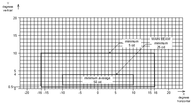
Figure 9.14‑1: Isocandela Diagram for Taxiway Centreline Lights and Stop Bar Lights on Straight Sections of Taxiways intended for use in RVR conditions of 350 m or greater
Notes: 1. The intensity values have taken into account high background luminance, and possibility of deterioration of light output resulting from dust and local contamination. 2. Where omnidirectional lights are used they must comply with the vertical beam spread. 3. See the collective notes at Paragraph 9.14.1 for these isocandella diagrams. |

Figure 9.14‑2: Isocandela Diagram for Taxiway Centreline Lights and Stop Bar Lights on Curved Sections of Taxiways intended for use in RVR conditions of 350 m or greater
Notes: 1. The intensity values have taken into account high background luminance, and possibility of deterioration of light output resulting from dust and local contamination. 2. Lights on curves to have light beam toed-in 15.75º with respect to the tangent of the curve. 3. These beam coverages allow for displacement of the cockpit from the centreline up to distance of the order of 12 m as could occur at the end of curves. 4. See collective notes at Paragraph 9.14.1 for these isocandela diagrams. |

Figure 9.14‑3: Isocandela Diagram for Taxiway Centreline Lights and Stop Bar Lights on Taxiways intended for use in RVR conditions of less than a value of 350 m — for use on straight sections of taxiway where large offsets can occur. Also for Runway Guard Lights Configuration B
Notes: 1. These beam coverages allow for displacement of the cockpit from the centreline of up to 12 m and are intended for use before and after curves. 2. See collective notes at Paragraph 9.14.1 for these isocandela diagrams. |

Figure 9.14‑4: Isocandela Diagram for Taxiway Centreline Lights and Stop Bar Lights on Taxiways intended for use in RVR conditions of less than a value of 350 m — for use on straight sections of taxiway where large offsets do not occur
Notes: 1. These beam coverages are suitable for a normal displacement of the cockpit from the centreline of up to 3 m. 2. See collective notes at Paragraph 9.14.1 for these isocandella diagrams. |

Figure 9.14‑5: Isocandela Diagram for Taxiway Centreline Lights and Stop Bar Lights on Taxiways intended for use in RVR conditions of less than a value of 350 m — for use on curved sections of taxiway
Notes: 1. Lights on curves to have light beam toed-in 15.75º with respect to the tangent of the curve. 2. See collective notes at Paragraph 9.14.1 for these isocandella diagrams. |
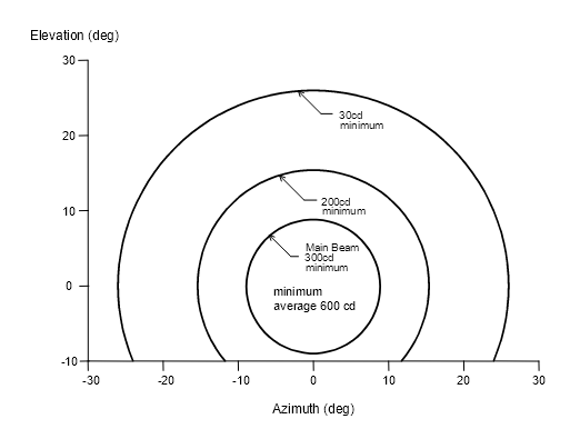
Figure 9.14‑6: Isocandela Diagram for Each Light in Runway Guard Lights. Configuration A.

Figure 9.14‑7: Method of Establishing Grid Points to be used for Calculation of Average Intensity of Taxiway Centreline Lights and Stop Bar Lights

Figure 9.15‑1 (a): Typical Taxiway Centreline Lights Layout

Figure 9.15-1 (b): Typical Taxiway Centreline Lights Layout
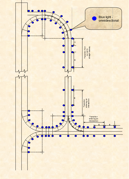
Figure 9.15‑2: Typical Taxiway Edge Lights Layout
Note: Previous apron floodlighting standards called for different illuminance specifications for international and domestic aprons, with higher illuminance specifications for the international aprons. With airlines now conducting both domestic and international operations, setting apron floodlighting requirements based on the international or domestic usage is no longer appropriate and can inhibit flexibility of apron usage. This Section will use aeroplane size as the criterion for illuminance specification. |
9.16.1.1 ICAO establishes only one apron floodlighting standard. However, Australia will retain the two tier system, viz. a higher illuminance standard for aprons intended to serve larger aeroplanes, and a lower illuminance standard for aprons intended to serve only smaller aeroplanes. For the purpose of this Section, aeroplanes bigger than code 3C are treated as larger aeroplanes. Code 3C aeroplanes and aeroplanes smaller than code 3C are treated as smaller aeroplanes.
9.16.1.2 An existing floodlighting system on an apron currently used by larger aeroplanes which does not meet the specifications of this Section does not need to be replaced until the system is due for replacement, or there is a significant change in the usage of the apron by larger aeroplanes.
9.16.2.1 Apron floodlighting, in accordance with this Section, must be provided on an apron, or the part of an apron, and on a designated isolated aircraft parking position, intended for use at night.
9.16.3.1 Apron floodlighting must be located so as to provide adequate illumination on all the apron service areas that are intended for use at night.
9.16.3.2 If an apron taxiway is not provided with taxiway lighting, then it must be illuminated by the apron floodlighting in accordance with either 9.16.4.3(b) or 9.16.4.4(b).
9.16.3.3 Apron floodlights must be located and shielded so that there is a minimum of direct or reflected glare to pilots of aircraft in flight and on the ground, air traffic controllers, and personnel on the apron.
Note: See also Section 9.21 in regard to upward component of light. |
9.16.3.4 An aircraft parking position must receive, as far as practicable, apron floodlighting from two or more directions to minimise shadows.
Note: For apron floodlighting purpose, an aircraft parking position means a rectangular area subtended by the wing span and overall length of the largest aircraft that is intended to occupy that position. |
9.16.3.5 Apron floodlighting poles or pylons must not penetrate the obstacle limitation surfaces.
9.16.4.1 To minimise the chance of an illuminated rotating object such as a propeller appearing stationary, at major aerodromes, the apron floodlighting is to be distributed across the phases of a three-phase power supply system to avoid a stroboscopic effect.
Note: Aerodrome operators are strongly encouraged to apply Paragraph 9.16.4.1 to aprons at ALL aerodromes. |
9.16.4.2 The spectral distribution of apron floodlights must be such that the colours used for aircraft marking connected with routine servicing, and for surface and obstacle marking, can be correctly identified. Monochromatic lights must not to be used.
9.16.4.3 The average illuminance of an apron intended for larger aeroplanes must be at least as follows:
(a) at an aircraft parking position:
(i) for horizontal illuminance – 20 lux with a uniformity ratio (average to minimum) of not more than 4 to 1; and
(ii) for vertical illuminance – 20 lux at a height of 2 m above the apron in the relevant parking direction, parallel to the aeroplane centreline;
(b) at other apron areas, horizontal illuminance at 50 per cent of the average illuminance on the aircraft parking position with a uniformity ratio (average to minimum) of not more than 4 to 1.
Note: The uniformity ratio between the average of all values of illuminance, measured over a grid covering the relevant area, and the minimum illuminance within the area. A 4:1 ratio does not necessarily mean a minimum of 5 lux. If an average illuminance of say 24 lux is achieved, then the minimum should be not less than 24/4 = 6 lux. |
9.16.4.4 The average illuminance of an apron intended to be used only by smaller aeroplanes must be at least as follows:
(a) at an aircraft parking position:
(i) for horizontal illuminance – 5 lux with a uniformity ratio (average to minimum) of not more than 4 to 1; and
(ii) for vertical illuminance – 5 lux at a height of 2 m above the apron in the relevant parking direction, parallel to the aeroplane centreline;
(b) at other apron areas, horizontal illuminance graded to a minimum of 1 lux at the apron extremities or 2 lux for apron edge taxiways which do not have taxiway lights.
9.16.4.5 A dimming control may be provided to allow the illuminance of an aircraft parking position on an active apron that is not required for aircraft use to be reduced to not less than 50 per cent of its normal values.
9.16.4.6 At an aerodrome where PAL activates the apron floodlighting, the apron floodlighting must achieve normal illuminance within 2 minutes of activation.
9.16.4.7 For aprons used by larger aeroplanes, the apron floodlighting must:
(a) be included in the aerodrome secondary power supply system; and
(b) be capable, following a power interruption of up to 30 seconds, of being re-lit and achieving not less than 50 per cent of normal illuminance within 60 seconds.
9.16.4.8 If existing or proposed floodlights cannot meet the requirement of Paragraph 9.16.4.7, auxiliary floodlighting must be provided that can immediately provide at least 2 lux of horizontal illuminance of aircraft parking positions. This auxiliary floodlighting must remain on until the main lighting has achieved 80 per cent of normal illuminance.
9.16.4.9 Each minimum illuminance value mentioned in this Section is maintained illuminance below which the actual value must not fall.
9.16.4.10 Each floodlight design must meet a target value which allows for a depreciation and maintenance factor that is appropriate for the particular floodlighting system.
Note: The floodlight designer may choose the factor provided it is appropriate for the particular floodlighting system. |
9.16.4.11 The design, installation, verification and subsequent management of an apron floodlighting system must be in accordance with Australian Standard AS/NZS 3827.1, Lighting system performance – Accuracies and tolerances. Part 1: Overview and general recommendations.
9.17.1.1 A visual docking guidance system must be provided at an apron aircraft parking position equipped with a passenger loading bridge, where the characteristics of the passenger loading bridge require precise positioning of an aircraft.
9.17.1.2 The provisions of this Section do not, of themselves, require the replacement of existing installations. When existing installations are to be replaced due to obsolescence, facility upgrade, change of apron layout, change of passenger loading bridge, change of aircraft category, change of operational requirements, or similar reasons, all new and/or replacement visual docking guidance systems must comply with this Section.
9.17.2.1 The system must provide both azimuth and stopping guidance.
9.17.2.2 The azimuth guidance unit and the stopping position indicator must be adequate for use in all weather, visibility, background lighting, and pavement conditions for which the system is intended, both by day and night, but must not dazzle the pilot.
Note: Care is required in both the design and on-site installation of the system to ensure that reflection of sunlight, or other light in the vicinity, does not degrade the clarity and conspicuity of the visual cues provided by the system. |
9.17.2.3 The azimuth guidance unit and the stopping position indicator must be of a design such that:
(a) a clear indication of malfunction of either or both is available to the pilot; and
(b) they can be turned off.
9.17.2.4 The azimuth guidance unit and the stopping position indicator must be located in such a way that there is continuity of guidance between the aircraft parking position markings, the aircraft stand manoeuvring guidance lights, if present, and the visual docking guidance system.
9.17.2.5 The accuracy of the system must be adequate for the type of loading bridge and fixed aircraft servicing installations with which it is to be used.
9.17.2.6 The system must be usable by all types of aircraft for which the aircraft parking position is intended, preferably without selective operation.
9.17.2.7 If selective operation is required to prepare the system for use by a particular type of aircraft, then the system must provide an identification of the selected aircraft type to both the pilot and the system operator as a means of ensuring that the system has been set properly.
9.17.3.1 The azimuth guidance unit must be located on or close to the extension of the parking position centreline ahead of the aircraft so that its signals are visible from the cockpit of an aircraft throughout the docking manoeuvre and aligned for use at least by the pilot occupying the left seat.
9.17.3.2 Systems with azimuth guidance aligned for use by the pilots occupying both the left and right seats are acceptable.
9.17.4.1 The azimuth guidance unit must provide unambiguous left/right guidance which enables the pilot to acquire and maintain the lead-in line without over controlling.
9.17.4.2 When azimuth guidance is indicated by colour change, green must be used to identify the centreline and red for deviations from the centreline.
9.17.5.1 The stopping position indicator must be located in conjunction with, or sufficiently close to, the azimuth guidance unit so that a pilot can observe both the azimuth and stop signals without turning the head.
Note: Some existing systems at Australian aerodromes require the pilot to turn the head to see the stopping position indicator. These systems may remain in service, in accordance with Paragraph 9.17.1.2 above. |
9.17.5.2 The stopping position indicator must be usable at least by the pilot occupying the left seat.
9.17.5.3 Systems with stopping position indicator usable by the pilots occupying both the left and right seats are acceptable.
9.17.6.1 The stopping position information provided by the indicator for a particular aircraft type must account for the anticipated range of variations in pilot eye height and/or viewing angle.
9.17.6.2 The stopping position indicator must show the stopping position of the aircraft for which the guidance is being provided, and must provide closing rate information to enable the pilot to gradually decelerate the aircraft to a full stop at the intended stopping position.
9.17.6.3 The stopping position indicator must provide closing rate information over a distance of at least 10 m.
9.17.6.4 When stopping guidance is indicated by colour change, green must be used to show that the aircraft can proceed and red to show that the stop point has been reached except that for a short distance prior to the stopping point a third colour may be used to warn that the stopping point is close.
9.17.7.1 A parking position identification sign must be provided at an aircraft parking position equipped with a visual docking guidance system.
9.17.7.2 A parking position identification sign must be located so as to be clearly visible from the cockpit of an aircraft prior to entering the parking position.
9.17.7.3 A parking position identification sign must consist of a numeric or alphanumeric inscription that is:
(a) in white on a black background; and
(b) illuminated at night by a continuous line of green light outlining the inscription.
Note: Green neon tubing illumination is satisfactory. |
9.17.8.1 Due to the large variety of different type of visual docking guidance systems to be found in operation at aerodromes, information on particular types installed is published in aeronautical information publications, for use by pilots.
9.17.8.2 Aerodrome operators must notify the Procedure Design Section of Airservices Australia, the details of their aircraft docking guidance system intended for use for International operations.
9.17.8.3 The information to be provided is to include:
(a) type of visual docking guidance system;
(b) descriptive information, including illustrations where appropriate, for any type of system not currently described in AIP Australia; and
(c) parking positions at which the system is installed.
9.17.8.4 Initial and subsequent notification must be in accordance with Chapter 5, Aerodrome Information for AIP and Chapter 10, Operating Standards for Certified Aerodromes. The visual docking guidance system information must also be recorded in the Aerodrome Manual.
9.18.1.1 When a runway or taxiway, or portion thereof is closed, all aerodrome lighting thereon is to be extinguished. The lighting is to be electrically isolated or disabled, to prevent inadvertent activation of the lights.
Note: 1. Restricted operation of the lights is permissible for maintenance or related purposes. 2. It is acceptable for short time periods, to cover lights with an opaque cover provided that: (a) the cover is firmly attached to the ground, so that it cannot be unintentionally dislodged, and (b) the cover, and its means of attachment to the ground, do not pose a hazard to aircraft, and do not constitute an object that is not lightweight and frangible. |
9.18.1.2 Where a closed runway, taxiway, or portion thereof, is intercepted by a useable runway or taxiway which is used at night, unserviceability lights are to be placed across the entrance to the closed area at intervals not exceeding 3 m.
9.18.2.1 When any portion of a taxiway, apron, or holding bay is unfit for movement of aircraft, but it is still possible for aircraft to bypass the area safely, and the movement area is used at night, unserviceability lights are to be used.
9.18.2.2 The lights are to be placed at intervals sufficiently close so as to delineate the unserviceable area and, in any case, must not be more than 7.5 m apart.
9.18.3.1 Unserviceability lights are to be steady red lights.
9.18.3.2 The lights are to have an intensity sufficient to ensure conspicuity considering the intensity of the adjacent lights and the general level of illumination against which they would normally be viewed. In no case is the intensity to be less than 10 cd of red light.
9.19.1.1 Vehicle warning lights, as required by subsection 10.9.2, must be provided to indicate to pilots and others the presence of vehicles or mobile plant on the movement area.
9.19.1.2 A vehicle warning light or lights must be mounted on the top of the vehicle, so as to provide 360° visibility.
9.19.1.3 The lights must be amber/yellow/orange, and be flashing or rotating of a standard type commercially available as an automobile accessory.
Note: International experience has shown the following specification to be particularly suitable. Yellow light, with a flash rate of between 60 and 90 flashes per minute, with a peak intensity of between 40 cd and 400 cd, a vertical beam spread of 12°, and with the peak intensity located at approximately 2.5° vertical. |
9.19.1.4 For lighting of rescue and fire fighting vehicles, see MOS 139 Subpart H, Chapter 4.
9.19.1.5 For emergency or security vehicles not dedicated to aerodrome use, vehicle warning lights complying with the local traffic code are acceptable for on-aerodrome operation.
9.19.2.1 Works limit lights are provided to indicate to persons associated with the works organisation the limit of the works area.
9.19.2.2 Works limit lights must be portable, amber/yellow/orange lights of a standard type commercially available as works warning lights. Alternatively they may be liquid fuel lanterns with amber/yellow/orange lenses.
9.19.3.1 CASA does not regulate the lighting of roads and car parks, other than ensuring compliance with Paragraph 9.1.3.
9.19.3.2 Where road and car park lighting is required on an aerodrome, the aerodrome operator is advised to consult with the relevant local road authority or Australian Standards AS 1158 – Code of Practice for Public Lighting.
9.19.4.1 A road-holding position light must be provided at each road-holding position serving a runway if it is intended that the runway will be used in RVR conditions of less than 350 m.
9.19.4.2 A road-holding position light must:
(a) conform to the standards specified in ICAO Annex 14; or
(b) be capable of demonstrating an outcome equivalent to that of light which does conform.
Note: See subsection 11.1.4A for the mass and height limitations and frangibility requirements of navigation aids located on runway strips. |
9.20.1.1 The aerodrome operator must monitor and maintain all lights and lighting systems associated with the aerodrome visual ground aids, both day and night, on a continuing basis for correctness and so that they are easily seen. Monitoring of lighting systems such as T-VASIS, PAPI and approach lighting must be carried out in accordance with the frequencies and procedures set out in the Aerodrome Manual. Other aerodrome lights must be monitored during the daily serviceability inspections and they must be switched on for this purpose.
9.20.1.2 Grass areas around lights must be maintained such that the lights are not in any way obscured. Lights must be kept free from dirt so as not to degrade their colour and conspicuousness. Damage to lights, including loss or degradation of light must be made good.
9.20.2.1 Any aerodrome light outage detected must be fixed as soon as is practicable. The specifications listed below are intended to define the maintenance performance level objectives. They are not intended to define whether the lighting system is operationally out of service. Nor are they meant to condone outage, but are intended to indicate when lighting outage must be notified to the NOTAM office. The specifications must be used as triggers for NOTAM action, to advise pilots of actual outage, unless the outage can be rectified before the next period of use.
9.20.2.2 For details of the raising of NOTAMs refer to Section 10.3.
9.20.2.3 A light is deemed to be on outage when the main beam is out of its specified alignment or when the main beam average intensity is less than 50 per cent of the specified value. For light units where the designed main beam average intensity is above the specified value, the 50 per cent value shall be related to that design value.
Note: For installations that were in existence prior to 2 May 2003, and where the design main beam average intensity values are unknown and/or unobtainable, the 50 per cent value shall be related to the specified value. |
9.20.2.4 A flashing or occulting light is deemed to be on outage when:
(a) the light ceases to flash or occult; or
(b) the frequency and/or duration of flash is outside the specified range by a factor of 2 to 1 or greater; or
(c) within a 10 minute period, more than 20% of flashes fail to occur.
9.20.2.5 A lighting system is deemed to be on outage when:
(a) in the case of a lighting system comprising less than 4 lights (e.g. intermediate holding position lights or runway threshold identification lights), any of the lights are on outage;
(b) in the case of a lighting system comprising 4 or 5 lights (e.g. wind direction indicator lights or runway guard lights), more than 1 light is on outage;
(c) in the case of a lighting system comprising 6 to 13 lights (e.g. threshold lights or LAHSO lights), more than 2 lights are on outage, or 2 adjacent lights are on outage;
(i) more than 5% of the lights are on outage in any of the following elements:
(A) the inner 450 m of the approach lighting system;
(B) the runway centreline lights;
(C) the runway threshold lights; or
(D) the runway edge lights; or
(ii) more than 10% of the lights are on outage in the touchdown zone lights; or
(iii) more than 15% of the lights are on outage in the approach lighting system beyond 450 m; or
(iv) in any case other than a barrette or a crossbar — 2 or more adjacent lights are on outage; or
(v) for a barrette or a crossbar — 3 or more adjacent lights are on outage; and
(e) in the case of a runway meant for take-off in visibility conditions of less than 550 m:
(i) more than 5% of the lights are on outage in any of the following elements:
(A) runway centreline lights (where provided); and
(B) runway edge lights; or
(ii) 2 or more adjacent lights are on outage; and
(f) in the case of a taxiway intended for use in RVR conditions of less 350 m, 2 or more adjacent taxiway centreline lights are on outage; and
(g) in the case of any other lighting system with more than 13 lights:
(i) more than 15% of the lights are on outage; or
(ii) 2 or more adjacent lights are on outage.
Note: For this subsection, a lighting system means lights used to illuminate a particular facility, for example: (a) all of the lights used to mark a threshold; or (b) all of the lights used to mark a runway end; or (c) all of the runway edge lights on a runway; or (d) all of the taxiway centreline lights on a length of taxiway between intersections. |
9.20.2.6 For a T-VASIS, the outage standards take into account both the number of outage lamps within a light unit, and also the number of light units within the T-VASIS system. The standards are:
(a) A T-VASIS light unit is deemed on outage when 3 or more lamps in the electrical (day) circuit are on outage, or when any of the lamps in the electrical (night) circuit is on outage.
(b) A T-VASIS system is deemed on outage when:
(i) bar units ― more than 2 light units or two adjacent light units are on outage;
(ii) fly-up units ― more than 1 light unit are on outage;
(iii) fly-down units ― more than 1 light unit are on outage.
(c) An AT-VASIS system is deemed on outage when:
(i) bar units ― more than 1 light unit is on outage,or
(ii) fly-up units ― any light unit is on outage,or
(iii) fly-down units ― any light unit is on outage.
(d) Whenever a red filter has deteriorated such that it does not produce the correct colour light beam, is missing, or is damaged, all the lamps within the affected light unit must be extinguished until the red filter is rectified. The affected light unit is included as an outage light unit when applying (b) or (c) above.
9.20.2.7 For a PAPI, the outage standards take into account both the number of lamps on outage within a light unit and also the number of light units within the PAPI system. The standards are:
(a) a PAPI light unit is deemed on outage when more than one lamp in a 3 or more lamp light unit is on outage, or any lamp in a less-than-3-lamp light unit is on outage;
(b) whenever a red filter has deteriorated such that it does not produce the correct colour light beam, is missing, or is damaged, all the lamps associated with that filter must be extinguished until the red filter is rectified. The affected lamp/s are included as outage lamps when determining (a) above.
(c) a double-sided PAPI system (i.e. 8 light units) is:
(i) deemed to be on outage but useable when all light units in one wing bar are fully functioning, and any light units in the other wing bar are on outage. The system may remain in use but a NOTAM must be issued detailing the number of light units on outage, and on which side of the runway they are; and
(ii) deemed on outage when one or more light units in each wing bar is on outage. The double-sided PAPI system must be extinguished until the system is rectified;
(d) a single-sided PAPI system (i.e. 4 light units) is deemed to be on outage when any light unit is on outage. The PAPI system must be extinguished until the system is rectified.
9.20.2.8 At an aerodrome where the lighting system is provided with interleaf circuitry, the lighting system is deemed to be on outage when any one of the circuits fails.
9.20.2.9 For a movement area guidance sign:
(a) the sign must be legible at all times; and
(b) any lamp outage in a sign must be fixed as soon as practicable.
Notes: 1. No specific standard is specified for the critical number of lamps on outage in an illuminated movement area guidance sign. The key requirement is the legibility of the sign inscription at all times. 2. The failure of movement area guidance sign illumination is not subject to notification by NOTAM. |
9.21.1.1 This Section supersedes a paper of the same name dated July 1988 issued by the Civil Aviation Authority and referred to in Australian Standard AS 4282-1997, Control of the obtrusive effects of outdoor lighting.
9.21.1A.1 This Section provides advice to those involved in the design or provision of lighting systems for use at or in the vicinity of an aerodrome. The intention is to minimise the potential hazard to aircraft operations from the lighting systems.
9.21.1A.2 If an aerodrome operator becomes aware that a lighting installation is proposed to be or is being installed in the vicinity of the aerodrome, it is in the aerodrome’s interest to make sure that the person responsible for the lighting system is made aware of the contents of this Section.
9.21.2.1 The Civil Aviation Safety Authority (CASA) has the power through regulation 94 of the Civil Aviation Regulations 1988 (CAR 1988), to require lights which may cause confusion, distraction or glare to pilots in the air, to be extinguished or modified. Ground lights may cause confusion or distraction by reason of their colour, position, pattern or intensity of light emission above the horizontal plane. The text of regulation 94 is reproduced below for reference:
94 Dangerous lights
(1) Whenever any light is exhibited at or in the neighbourhood of an aerodrome, or in the neighbourhood of an air route or airway facility on an air route or airway, and the light is likely to endanger the safety of aircraft, whether by reason of glare, or by causing confusion with, or preventing clear reception of, the lights or signals prescribed in Part 13 or of air route or airway facilities provided under the Air Services Act 1995; CASA may authorise a notice to be served upon the owner of the place where the light is exhibited or upon the person having charge of the light directing that owner or person, within a reasonable time to be specified in the notice, to extinguish or to screen effectually the light and to refrain from exhibiting any similar light in the future.
(2) An owner or person on whom a notice is served under this regulation must comply with the directions contained in the notice.
Penalty: 25 penalty units.
(2A) An offence against subregulation (2) is an offence of strict liability.
Note For strict liability, see section 6.1 of the Criminal Code.
(2B) It is a defence to a prosecution under subregulation (2) if the defendant had a reasonable excuse.
Note A defendant bears an evidential burden in relation to the matter in subregulation (2B) (see subsection 13.3 (3) of the Criminal Code).
(3) If any owner or person on whom a notice under this regulation is served fails, within the time specified in the notice, to extinguish or to screen effectually the light mentioned in the notice, CASA may authorise an officer, with such assistance as is necessary and reasonable, to enter the place where the light is and extinguish or screen the light, and may recover the expenses incurred by CASA in so doing from the owner or person on whom the notice has been served.
9.21.3.1 Advice for the guidance of designers and installation contractors is provided for situations where lights are to be installed within a 6 km radius of a known aerodrome. Lights within this area fall into a category most likely to be subjected to the provisions of the regulation 94 of CAR 1988. Within this large area there exists a primary area which is divided into four light control zones: A, B, C and D. These zones reflect the degree of interference ground lights can cause as a pilot approaches to land.
9.21.3.2 The primary area is shown in Figure 9.21‑1. This drawing also nominates the intensity of light emission above which interference is likely. Lighting projects within this area should be closely examined to see they do not infringe the provision of regulation 94 of CAR 1988.
9.21.3.3 The fact that a certain type of light fitting already exists in an area is not necessarily an indication that more lights of the same type can be added to the same area.
9.21.3.4 Even though a proposed installation is designed to comply with the zone intensities shown in Figure 9.21‑1, designers are advised to consult with CASA as there may be overriding factors which require more restrictive controls to avoid conflict.
9.21.4.1 Light fittings chosen for an installation should have their isocandela diagram examined to ensure the fitting will satisfy the zone requirements. In many cases the polar diagrams published by manufacturers do not show sufficient detail in the sector near the horizontal, and therefore careful reference should be made to the isocandela diagram.
9.21.4.2 For installations where the light fittings are selected because their graded light emission above horizontal conform with the zone requirement, no further modification is required.
9.21.4.3 For installations where the light fitting does not meet the zone requirements, then a screen should be fitted to limit the light emission to zero above the horizontal. The use of a screen to limit the light to zero above the horizontal is necessary to overcome problems associated with movement of the fitting in the wind or misalignment during maintenance.
9.21.5.1 Coloured lights are likely to cause conflict irrespective of their intensity as coloured lights are used to identify different aerodrome facilities. Proposals for coloured lights should be referred to the Authority for detailed guidance.
9.21.6.1 Check with the nearest CASA office for likely effect on aircraft operations of proposed lighting in the vicinity of an aerodrome.

Figure 9.21‑1: Maximum lighting intensities
9.22.1.1 The type of cable usually used in Australia for the series current electrical supply to aerodrome lighting fittings is a single core 6 mm² (7/1.04 mm) plain annealed copper conductor covered with a polyethylene insulation and an overall nylon sheath. It may be safely operated at 3000 volt. The nylon sheath provides additional protection against rough handling during installation, and also prevents damage by termites. The cable is suitable for direct burial in the ground.
9.22.1.2 As the series current system, and the cable used, was significantly different from normal electrical practice, the Department of Civil Aviation (DCA) referred the matter to the Standards Association of Australia in 1958.
9.22.1.3 Committee EL/1, the committee responsible for the SAA Wiring Rules, advised DCA in 1959 that it recommended to all Statutory Authorities that such installations be treated as ‘unusual installations’ that did not have to strictly comply with certain parts of the Wiring Rules, provided certain precautions were observed.
9.22.2.1 Firstly it allowed unarmoured cable to be used for high voltage, and that the cable could be installed at a depth of 450 mm instead of the 750 mm required for high voltage in the Wiring Rules.
9.22.2.2 Secondly, it allowed the cable to be buried directly in the ground without mechanical protection against digging.
9.22.2.3 The dispensation was reaffirmed to the Department of Aviation in 1983, and again to the Civil Aviation Authority in 1993.
9.22.3.1 The conditions under which the dispensation was sanctioned by the SAA are:
(a) the series lighting circuit which they serve are normally isolated from the supply mains;
(b) the location of the cables is carefully and permanently marked;
(c) earthworks and excavations on an aerodrome are very strictly controlled; and
(d) the lighting circuits are not normally energised during daylight hours when earthworks could be in progress.
9.22.4.1 The dispensation only applies to the Movement Area. In other areas of the aerodrome, such as within the building area, the dispensation does not apply.
9.22.4.2 To satisfy Paragraph 9.22.3.1(b), cables should as far as practicable, be laid in straight lines. Suitably engraved permanent cable markers should be installed above all buried cable. The markers should be flush with the finished ground surface and should be located at changes of direction, duct ends, at no more than 100 metre intervals on long straight runs, and at points of entry into buildings.
9.22.4.3 Accurate and up to date plans of the aerodrome should be maintained which record actual locations of all cables installed on the aerodrome.
9.22.4.4 To satisfy condition (d), at aerodromes where lighting systems may be used by day, including visual approach slope guidance systems, or where pilot activation of aerodrome lighting is possible, local procedures should be established that ensure that aerodrome lighting systems are electrically isolated when any works are in progress that could endanger such cable on an aerodrome.
9.22.4.5 A copy of the most recent Standards Australia letter dated 7 September 1993, is attached for reference in Figure 9.22‑1 and Figure 9.22‑2.
9.22.5.1 Not withstanding anything in this Section, it is the aerodrome operators’ responsibility to ensure that any proposed installation on their aerodrome meets the requirements of the relevant Supply Authority.

Figure 9.22‑1: SAA Letter Regarding Use of Unarmoured Cables
Figure 9.22‑2: SAA Letter Regarding Use of Unarmoured Cables - Page 2
10.1.1.1 This Chapter sets out the standards to be incorporated in operating procedures at certified aerodromes, including those procedures to be documented in the aerodrome manual.
10.1.1.2 This Chapter also contains information on aerodrome Safety Management System (SMS). As prescribed in CASR Part 139, SMS will be applicable at aerodromes accommodating international operations with effect from November 2005. And a later date, yet to be determined, for domestic aerodromes. All aerodrome operators are encouraged to adopt SMS as early as possible but until such time as specified in the regulations, adoption of SMS is voluntary.
10.1.1.3 The standards are to be applied in a manner commensurate with the type and level of aircraft activities at the particular aerodrome. For example, Section 10.17 on low visibility operations, will not apply to all aerodromes.
10.1.2.1 As an integral part of the certification process, an aerodrome manual must be prepared setting out a range of information and operating procedures specified in CASR Part 139. Although the certification process does not involve a separate approval process for the aerodrome manual, the information contained in the manual must be acceptable to CASA.
10.1.2.2 The aerodrome manual must be in a format that can be readily updated.
10.1.2.3 The contents of the aerodrome manual may be presented in a single bound document or in a number of separate documents. For example, at major aerodromes, the aerodrome emergency plan and the airside vehicle control handbook may each be a large stand-alone publication. Where this is the case, the aerodrome manual must effectively integrate the component publications by appropriate references.
10.1.2.4 An up-to-date copy of all components of the aerodrome manual must be kept at the business premises of the aerodrome operator and made available for CASA audit purposes.
10.1.3.1 Persons engaged to perform the reporting officer functions, including aerodrome serviceability inspections; and works safety officer functions must be adequately trained for the job. In addition, Aerodrome Technical Inspections must be carried out by technically qualified and competent persons.
10.1.3.2 CASA is primarily concerned with the competency of persons involved with aerodrome safety functions. Essential competencies will include:
(a) inspect and report on the physical characteristics and conditions of the aerodrome;
(b) inspect and report on aerodrome lighting systems;
(c) inspect and report on the OLS;
(d) initiating a NOTAM;
(e) use of radio, and
(f) supervise the safety of aerodrome works.
10.1.3.3 There are no mandatory provisions which regulate private training organisations or aerodrome operator training initiatives; but aerodrome operators must be able to demonstrate that persons carrying out aerodrome safety functions, have had the appropriate training and experience to undertake those functions
Notes: 1. CASA has endorsed the Australian Airports Association (AAA) competency based training model, as an acceptable means of demonstrating appropriate training and experience. 2. Guidance on the training of aerodrome personnel can be found in the associated Advisory Circular. |
10.1.4.1 In line with international practice, SMS will be progressively introduced at Australian aerodromes, with particular emphasis initially on aerodromes used in international operations.
10.1.4.2 Safety culture and ongoing commitment of senior management are essential ingredients for a successful SMS, along with the setting of safety objectives, clear responsibilities, ongoing hazard identification and reporting, training and performance measurement.
Note: In conjunction with the Australian Airports Association, an Advisory Circular will be prepared to provide guidelines on the preparation of a SMS. It is important to appreciate, all SMSs are different as they relate to site-specific situations and management structures. Aerodromes differ, inter-alia as a result of size, complexity and types of operation. |
10.1.4.3 The SMS does not necessarily generate a need for an additional set, or duplication of documents. The SMS requirements should complement the procedures set out in the aerodrome manual.
10.2.1.1 Whilst aerodrome serviceability inspections are essentially visual checks, the process must include appropriate remedial actions where there is an immediate affect on the safety of aircraft operations. If the identified fault cannot be remedied before the next aircraft operations, then the matter must be reported to the NOTAM office. Examples of this type of remedial action include replacement of broken light lenses, lamp replacement or removal of debris from the movement area.
10.2.1.2 The operator of a certified aerodrome is required to arrange for aerodrome serviceability inspections to be carried out each day and after a severe wind or rain storm, or when requested by air traffic control or by CASA.
10.2.1.3 Subject to CASA agreement, the frequency of inspections may be reduced to not less than 2 per week, at aerodromes with low numbers of traffic movements.
10.2.1.4 Aerodrome reporting is the notification of changes to the published aerodrome information or any other occurrence or emergency affecting the availability of the aerodrome and safety of aircraft using the aerodrome. The occurrences may be known beforehand, as planned aerodrome works, or discovered during an inspection of the aerodrome or obstacle limitation surfaces.
10.2.1.5 Particulars of the procedures for carrying out serviceability inspections, including the use of a checklist, and for reporting any changes to aerodrome information or for requesting the issue of a NOTAM; are to be included in the aerodrome manual.
10.2.2.1 Any significant object found in the course of the inspection, including aircraft parts which may have fallen from the aircraft, or the remains of birds which may have been struck by an aircraft, must be reported immediately to Air Traffic Control, where appropriate, and to the Australian Transport Safety Bureau (ATSB).
Note: Any bird strike incident is to be reported to ATSB. Contact ATSB for the format of reporting details. |
10.2.3.1 The inspection must check for the presence of:
(a) ponding;
(b) cracking or spalling;
(c) rubber build up;
(d) surface irregularities;
(e) damage caused by spillage of corrosive fluids;
(f) pipe drain faults particularly in fine grain non cohesive subgrades, in high rainfall areas;
(g) scour or erosion ditches;
(h) termite mounds or other ground obstacles obscured by long grass;
(i) soft ground, particularly in combination with surface roughness and slipperiness; and
(j) any other sign of pavement distress which has the potential to develop quickly into a hazardous situation.
10.2.4.1 The inspection must check for:
(a) loss of visibility of markers and markings;
(b) use of incorrect markers and markings;
(c) any disturbance to level and alignment of lights;
(d) visual light intensity check; does a light stand out less bright than others in the same system?
(e) discoloured or dirty lenses;
(f) outage lamps, incorrect lamps fitted, or lamps fitted wrongly;
(g) the condition of the frangibility of light bases;
(h) exposed edges around footings and other aerodrome installations;
(i) damage to wind indicator assembly or mounting; and
(j) damage to wind indicator sleeve fabric, or loss of conspicuous colour.
10.2.5.1 The inspection must check for:
(a) foreign objects, such as aircraft fastening devices and other parts,
(b) mechanics tools, small items of equipment and personal items;
(c) debris, such as sand, loose rocks, concrete, wood, plastic, pieces of tyre and mud; and
(d) with particular vigilance during and after construction activity, where vehicles and plant travel over unpaved areas under wet conditions.
10.2.6.1 The aerodrome operator must have procedures and equipment in place to enable inspection personnel to identify objects protruding through the OLS. Equipment should include appropriate instrumentation, such as:
(a) a hand held clinometer;
(b) ‘sighting plane’ installations; or
(c) more formal survey equipment.
10.2.7.1 The inspection must include:
(a) the condition of aerodrome fencing, particularly in critical areas;
(b) climatic or seasonal considerations, such as the presence of birds at certain times of the year, or related to the depth of water in drainage ponding areas;
(c) possible shelter provided by aerodrome infrastructure such as buildings, equipment and gable markers;
(d) bird hazard mitigating procedures incorporated in the environmental management procedures for the aerodrome;
(e) off-airport attractors like animal sale yards, picnic areas, aeration facilities and waste disposal or landfill areas, and
(f) use of harassment procedures where appropriate.
10.2.8.1 The bearing strength of a runway strip will only be required to be assessed where an unsealed runway is not marked and the whole of the runway strip is available for aircraft operations.
10.2.8.2 Whilst discretion and judgement together with local knowledge, will always form part of empirical assessment of bearing capacity, appropriate test procedures must be in place for the practical guidance of persons making the assessment. Simple test procedures can be devised such as those involving:
(a) use of a crowbar when a dry surface may conceal a soft unserviceable base;
(b) the back of a pick, in the hands of someone with practical pavement experience; or
(c) a suitably laden utility or truck to simulate the wheel loads of user aircraft.
10.2.9.1 Daily serviceability inspection must include checking any outstanding NOTAM for the aerodrome. Check that the contents of the NOTAM, particularly the effective period(s) are still current.
10.2.10.1 The inspection must check for damaged fences, open gates and signs of attempted entry by either animals or humans.
10.2.11.1 Where provided by the aerodrome operator, the inspection must check that the equipment is functional.
10.2.12.1 The aerodrome operator must maintain aerodrome inspection logbooks for recording the date and time of each aerodrome serviceability inspection, the results of each inspection and any action taken. Logbooks must be retained for at least 2 years.
10.3.1.1 A NOTAM is used to inform pilots and aircraft operators of significant changes to the aerodrome that may impact on aircraft operations. This is one of the most important aerodrome safety functions, so the process and procedures for initiating NOTAMs must be clearly set out in the Aerodrome Manual and all the persons involved must be fully informed and trained. A NOTAM may be originated and cancelled by the nominated reporting officer or relevant Airservices Australia or CASA officer.
10.3.1.2 For changes to navigation aids, MBZ/CTAF frequencies or special procedures, NOTAM may be originated by a relevant services provider such as Airservices or a CASA officer. Where a navigation aid is owned and maintained by the aerodrome operator, a NOTAM to notify changes to its status may be originated by the nominated reporting officer.
10.3.2.1 Where a change in the aerodrome condition requires a NOTAM to be issued, the nominated reporting officer must send the notification to the NOTAM Office (NOF) by FAX or by telephone. Telephone advice must be confirmed in writing as soon as possible.
10.3.2.2 The following occurrences must be reported to the Australian NOTAM Office:
(a) changes (temporary or permanent) in the published aerodrome information including additional changes to current permanent NOTAMs;
(b) aerodrome works affecting runways or the obstacle limitation surfaces, including time-limited works that require more than 10 minutes to re‑instate to serviceable order;
(c) unserviceable portions of the runway or failure in aerodrome lighting or obstacle lighting;
(d) temporary obstacles to aircraft operations;
(e) a significant increase in, or concentration of birds or animals on or in the vicinity of the aerodrome;
(f) changes in excess of 0.05% of the published gradient data;
(g) emergence of new obstacles;
(h) when a radio navigation aid or landing aid owned by the aerodrome operator is unserviceable or returned to service;
(i) when an Aerodrome Frequency Response Unit owned by the aerodrome operator is unserviceable or returned to service; and
(j) any other significant event which affects the safety of aircraft using the aerodrome.
10.3.2.3 Reporting to NOTAM Office must be carried out as expeditiously as possible. If all the relevant information cannot be provided at once, the matter must still be reported, and subsequent details can be issued by further NOTAM. When in doubt, err on the side of safety.
Note: To avoid overloading the NOTAM system, non-safety critical failures are not normally reported. For example, runway strip condition is not normally reported. Similarly, if a section of taxiway or apron is unserviceable, including some of the taxiway lighting or apron floodlighting being unserviceable, the area should be appropriately marked and lit, but the unserviceability does not normally need to be reported. If, however, the aerodrome only has one taxiway, and it is unserviceable, or only one apron, and the entire apron is unserviceable, it would be appropriate to notify these occurrences by NOTAM. |
10.3.2.4 In reporting changes for NOTAM action, the aerodrome operator must submit a report which includes:
(a) aerodrome name;
(b) the aerodrome facility affected and details of unserviceability;
(c) reason for change;
(d) start time and expected end time of the unserviceability; and
(e) daily duration or time schedule of the unserviceability, where applicable.
Note: Use of a form with standard headings will assist reporting. A sample aerodrome report form is shown in Section 10.4. |
10.3.2.5 After making a request to the NOF for a NOTAM, the reporting officer must obtain a copy of the subsequent NOTAM, in order to check the accuracy and to keep a record of its issue.
Note: To illustrate how changes to aerodrome information are communicated to pilots, some examples of NOTAMs are given in Section 10.5. This Section also provides a listing of general word abbreviations and phrase contractions to minimise the length of aerodrome NOTAMs. |
10.3.3.1 A NOTAM which is not a Permanent NOTAM is ‘time limited’. A time‑limited NOTAM will have an expected end time, and will lapse automatically.
10.3.4.1 A PERM NOTAM is originated in respect to permanent changes to aerodrome operational information published in AIP-ERSA. This information is passed to the NOTAM office which will issue the NOTAM and further pass the information on to AIS. AIS will incorporate the changes in the following edition of ERSA. The NOTAM is cancelled when the information is duly published in ERSA.
10.3.5.1 For changes to ERSA information which does not have an immediate impact on aircraft operations, the changes are not to be notified to NOF. Instead the aerodrome operator must notify AIS directly in writing of such changes. Example: change of a fuel supplier.
10.3.6.1 At aerodromes where a standing caution is included in ERSA for a bird or animal hazard, NOTAM must only be initiated where there is a significant increase of birds or animals. The NOTAM must provide specific information on species, period of concentration, likely location and flight path.
10.3.7.1 Any ERSA amendment which introduces a new visual aid, or the upgrading of an existing aid, must be referred to the appropriate CASA Aerodrome Inspector for clearance purposes. Certain visual aids have to be commissioned or flight checked before being brought into operational use.
10.3.8.1 Changes to Type A Chart information are not notified through NOTAM, however, ERSA must refer to the latest edition of the Type A Chart. Aerodrome operators must provide an amendment service for the Type A Chart information directly to holders of the Charts.
10.3.9.1 Whenever a report of ERSA changes is sent to the NOTAM Office or to the AIS, a copy of the report must also be sent to the appropriate CASA Aerodrome Inspector. The aerodrome operator must also ensure that the Aerodrome Manual is amended to reflect changes other than temporary changes.
10.3.10.1 Aerodrome operators must maintain a logbook showing details of all reports; check subsequent NOTAM or changes to AIP-ERSA for accuracy, and keep a copy of reports and NOTAM with the logbook.

10.5.1.1 To illustrate how changes to aerodrome information are communicated to pilots, some examples of NOTAM are given below.
10.5.1.2 Time-limited Work
C0174/91 NOTAMN
A) MARYBOROUGH 0174/91 (AD) 9106140900
B) 9106211000
C) 9106211600
E) RWY 17/35 WIP. MAE WILL CLR IF OPRT INDICATED.
10.5.1.3 Explanations of NOTAM Format
C0174/91 — the NOTAM number;
NOTAMN — a NOTAM containing new information;
A) Maryborough — name of aerodrome;
AD — information relating to aerodromes, or facilities thereon, including approach and landing aids, and the existence or removal of hazards or obstructions;
9106140900 — year/date/time of issue of NOTAM, in ten figures UTC, representing year, month, day, hour and minutes (Note, the year may be omitted);
B) 9106211000 — commencement of occurrence;
C) 9106211600 — cessation of occurrence and notification;
D) 1000/1600 — periods of activity within the period specified in Fields B and C;
E) The text of the NOTAM expressed as concisely as possible.
10.5.1.4 Major works in accordance with Method of Working Plan (MOWP) The MOWP will be faxed directly into the AVFAX electronic briefing system, with the pertinent stages of work activated by a trigger NOTAM quoting duration and AVFAX product code. Trigger NOTAM referring to specific stages of the MOWP will be issued as appropriate:
(a) C0943/91 NOTAMN
A) PERTH 0943/91 (AD) 9105200600
B) 9105222300
C) 9105270800 EST
E) RWY 06/24 NOT AVBL DUE WIP. REF MOWP 4/1987 ACT STAGE 1. AVFAX CODE XXXX.
(b) C0056/91 NOTAMN
A) COOLANGATTA 0056/91 (AD) 9106101002
B) 9106121100
C) 9106140600
E) RWY 14/32 NOT AVBL DUE WIP. REF MOWP QRO 86/7 ACT STAGE3. AVFAX CODE XXXX.
(c) C0934/95 NOTAMN
A) MACKAY C0934/95 (AD) 9505200600
B) 9506032200
C) 9506100600
D) 2200/0600 DAILY
E) RWY 06/24 WIP. REF MOWP 4/1993 AMENDMENT 3. 360M N END NOT AVBL.
(d) C0935/95 NOTAMN
A) MACKAY C0935/95 (AD) 9505200600
B) 9506032200
C) 9506040600
D) 2200/0600 DAILY
E) RWY 18/36 WIP. REF MOWP 4/1993 AMENDMENT 3. (followed by lengthy text of NOTAM).
10.5.1.5 Unserviceable movement areas.
(a) C0639/91 NOTAMN
A) KINGAROY 0639/91 (AD) 9107272100
B) 9107272100
C) 9108010600 EST
E) RWY 05/23 AND TWY PARL RWY 16/34. NOT AVBL DUE SOFT WET SFC. RWY 16/34 AVBL.
(b) C0021/91 NOTAMN
A) WONDAI 0021/91 (AD) 9103232200
B) 9103232200
C) 9103290600 EST
E) RWY 18/36 AMD. LEN. 140M S END NOT AVBL DUE ROUGH SFC. THR 36 DISP 200M. RWY 18 TORA 1264 (4146) TODA 1464 (4802) (2.3) ASDA 1264 (4146) LDA 1264 (4146) RWY 36 TORA 1264 (4146) TODA 1324 (4343) (1.6) ASDA 1264 (4146) LDA 1204 (3949) STODA RWY 18 1195 (3920) (1.6) 1339 (4392) (1.9) 1436 (4710) (2.2).
10.5.1.6 Surface bearing capacity. If the surface or part of the manoeuvring area is not serviceable for heavy aircraft a weight restriction may be imposed to allow light aircraft to operate.
C0281/91 NOTAMN
A) TARA 0281/91 (AD) 9108160400
B) 9108160400
C) 9108230600 EST
E) AD NOT AVBLTO ACFT ABV 1930 KG MTOW. DUE SOFT WET SFC.
10.5.1.7 Apron areas. These are not part of the manoeuvring area and therefore should not normally be the subject of NOTAM, but a NOTAM may be issued at minor aerodromes to indicate temporary parking arrangements.
C0256/91 NOTAMN
A) MERIMBULA 0256/91 (AD) 9108280500
B) 9108280500
C) 9108292600 EST
E) APRON CLOSED DUE WIP. LOAD UNLOAD ON RWY. RWY NOT AVBL WHEN ACFT STANDING THEREON. PILOTS SHOULD MAKE PROVISION FOR ALTN.
10.5.1.8 Obstacle information
(a) A permanent NOTAM to amend changes to declared distances owing to change in height of critical obstacle (trees).
C0166/95 NOTAMN
A) COOLANGATTA CO166/95 (AD) 9501210200
B) 9501210200
C) PERM
E) AMD RWY 14 GRADIENTS RWY 14 TORA 2042 (6698) TODA 2102 (6895) (2.82) ASDA 2042 (6698) LDA 2042 (6698) STODA RWY 14 1226 (4021) (2.2) 1716 (5628) (2.5) AMD AIP ERSA DATED 12 SEP 96.
(b) A temporary NOTAM to advise of a crane within the OLS area.
C0073/91 NOTAMN
A) COOLANGATTA 0073/91 (AD) 9104200700
B) 9104200700
C) 9106210600 EST
E) RWY 14/32 TEMPO TEMP OBST CRANE. 300FT AMSL BRG 076 MAG 2 NM FROM SE END OF RWY 14/32. INFRINGES HZS.
10.5.1.9 Runway Lighting Out of Service
C0091/91 NOTAMN
A) RICHMOND 0091/91 (AD) 9108510420
B) 9108162200
C) 9108192200
E) RWY LGT NOT AVBL.
10.5.1.10 Temporary or Permanent Withdrawal of Aerodrome Licence
(a) C0037/91 NOTAMN
A) MOROWA 0037/91 (AD) 9109251035
B) 9109251035
C) 9109260600
E) AD LICENCE SUSPENDED.
(b) C0048/91 NOTAMN
A) TURKEY CREEK 0048/91 (AD) 9103272218
B) 9103272220
C) PERM
E) AD DELICENSED.
(Abbreviations shown in singular words are also applicable to the plural of those words)
Words and Phrases | Abbreviation |
April | APR |
Abbreviated ‘T’ Visual Approach Slope Indicator System | AT-VASIS |
Abbreviated Visual Approach Slope Indicator System | A-VASIS |
Abeam | ABM |
About | ABT |
Above Aerodrome level | AAL |
Above ground level | AGL |
Above mean sea level | AMSL |
Accelerate-stop distance available | ASDA |
Accept or accepted | ACPT |
Active, activated, activity | ACT |
Actual time of arrival | ATA |
Actual time of departure | ATD |
Addition or additional | ADDN |
Adjacent | ADJ |
Advise | ADZ |
Aerodrome | AD |
Aerodrome Diagrams | ADDGM |
Aerodrome beacon | ABN |
Aerodrome control or aerodrome control tower | TWR |
Aerodrome Frequency Response Unit | AFRU |
Aerodrome obstruction chart | AOC |
Aerodrome reference point | ARP |
Aeronautical Information Circular | AIC |
Aeronautical Information Publication | AIP |
Aeronautical Information Service | AIS |
After....(time or place) | AFT |
Again | AGN |
Air Traffic Control (in general) | ATC |
Air traffic services | ATS |
Aircraft | ACFT |
Aircraft classification number | ACN |
Airport | AP |
Airway | AWY |
All-up-weight | AUW |
Alternate (Aerodrome) | ALTN |
Alternate or alternating (light alternates in colour) | ALTN |
Altimeter sub-scale setting to obtain elevation or altitude | QNH |
Altitude | ALT |
Amend(ed) | AMD |
Amendment (AIP Amendment) | AMDT |
Approach | APCH |
Approach lighting system | ALS |
Approximate(ly) | APRX |
Arrange | ARNG |
Arrive, or arrival | ARR |
As soon as possible | ASAP |
Asphalt | ASPH |
Associated with | ASSW |
Attention | ATTN |
Aircraft landing area (previously known as Authorised landing area) | ALA |
Authorised or authorisation | AUTH |
Automatic terminal information service | ATIS |
Auxiliary | AUX |
Available | AVBL |
Average | AVG |
Aviation gasoline | AVGAS |
Azimuth | AZM |
Beacon (aeronautical ground light) | BCN |
Bearing | BRG |
Becoming | BECMG |
Before | BFR |
Below | BLW |
Between | BTN |
Blue | B |
Boundary | BDRY |
Braking | BRKG |
Broken | BKN |
Building | BLDG |
By way of.. | VIA |
Calibration | CLBG |
Callsign (used to request a callsign) | CSGN |
Category | CAT |
Caution | CTN |
Celsius (Centigrade) | C |
Centreline | C/L |
Centimetre | CM |
Centre (runway) | C |
Change frequency to... | CF |
Channel | CH |
Check | CK |
Civil | CIV |
Clear, cleared to, clearance | CLR |
Clearway | CWY |
Close or closed or closing | CLSD |
Code number (runway) | CN |
Commissioned | CMSD |
Common Traffic Advisory Frequency | CTAF |
Communications | COM |
Completion or completed or complete | CMPL |
Concrete | CONC |
Condition | COND |
Confirm(ing) or I confirm | CFM |
Conical surface | COS |
Construction or constructed | CONST |
Contact | CTC |
Continue(s) or continued | CONT |
Continuous day and night service | H24 |
Continuous(ly) | CONS |
Co-ordinated Universal Time | UTC |
Correction or correct or corrected | COR |
Cover or covered or covering | COV |
Cross | X |
Crossbar (of approach lighting system) | XBAR |
Crossing | XNG |
Customs | CUST |
Danger or dangerous | DNG |
Decommissioned | DCMSD |
Degrees | DEG |
Delay or delayed | DLA |
Depart or departure | DEP |
Departure and Approach procedures | DAP |
Depth | DPT |
Destination | DEST |
Deteriorate, deteriorating | DTRT |
Deviation or deviated | DEV |
Direct | DCT |
Displaced | DISP |
Distance | DIST |
Distance measuring equipment | DME |
Divert or diverting or diversion | DIV |
Docking | DOCK |
Document | DOC |
Domestic | DOM |
Doppler VOR | DVOR |
Duration | DUR |
During | DRG |
Dust | DU |
Dust storm | DS |
East north-east | ENE |
East or east longitude | E |
East south-east | ESE |
Eastbound | EB |
Effective operational length | EOL |
Elevation | ELEV |
Emergency | EMERG |
Enroute Supplement Australia (AIP) | ERSA |
En route | ENRT |
Engine | ENG |
Equipment | EQPT |
Estimate or estimated | EST |
Estimated/estimating time of arrival | ETA |
Estimated/estimating time of departure | ETD |
Every | EV |
Except | EXC |
Exercises or exercising or to exercise | EXER |
Expect(ed)(ing) | EXP |
Expected approach time | EAT |
Extend(ed)(ing) | EXTD |
February | FEB |
Facility, facilities | FAC |
Facsimile transmission | FAX |
Feet (dimensional unit) | FT |
Field | FLD |
First | FST |
Flares | FLR |
Flight | FLG |
Flight information service | FIS |
Flight service (in general) | FS |
Flight service centre | FSC |
Flight service unit | FSU |
Flight plan (domestic) | PLN |
Fluctuating, fluctuation, fluctuated | FLUC |
Fly or flying | FLY |
Fog | FG |
Follow(s), following | FLW |
Forecast | FCST |
Frequency | FREQ |
Frequent | FRQ |
Friday | FRI |
From | FM |
General | GEN |
General Aviation | AWK or PVT |
General Aviation Aerodrome Procedures | GAAP |
Glide path | GP |
Glider | GLD |
Glider flying | GLY |
Gradual(ly) | GRADU |
Gravel | GRVL |
Green | G |
Ground | GND |
Hazard beacon | HBN |
Haze | HZ |
Heading | HDG |
Heavy | HVY |
Height or height above | HGT |
Helicopter | HEL |
Helicopter Landing Site | HLS |
Hertz (cycles per second) | HZ |
High intensity approach lighting | HIAL |
High intensity obstacle lights | HIOL |
High intensity runway lighting | HIRL |
Higher | HYR |
Hold(ing) | HLDG |
Homestead | HS |
Horizontal surface | HZS |
Hour | HR |
ICAO standard atmosphere | ISA |
Immediate(ly) | IMT |
Immigration | IMM |
Improve(ment), improving | IMPR |
Inbound | INBD |
Information | INFO |
Inner marker | IM |
Inoperative | INOP |
Install or installed or installation | INSTL |
Instrument | INSTR |
Instrument approach and landing charts | IAL |
Instrument approach chart | IAC |
Instrument flight rule | IFR |
Instrument landing system | ILS |
Instrument meteorological conditions | IMC |
Intensify(ing) | INTSF |
Intensity | INTST |
Intermittent(ly) | INTER |
International | INTL |
International Civil Aviation Organisation | ICAO |
Interrupt(ion)(ed) | INTRP |
Intersection | INT |
Isolated | ISOL |
January | JANUARY |
July | JULY |
June | JUNE |
Jet barrier | JBAR |
Jet stream | JTST |
Kilogram | KG |
Kilometres | KM |
Kilometres per hour | KMH |
Kilopascals | KPA |
Kilowatts | KW |
Knots | KT |
Landing | LDG |
Landing direction indicator | LDI |
Landing distance available | LDA |
Latitude | LAT |
Leave or leaving | LVE |
Left (runway identification) | L |
Length | LEN |
Level | LVL |
Light or lighting | LGT |
Lighted | LGTD |
Limited | LTD |
Local mean time | LMT |
Local, locally, location, located | LOC |
Localiser | LLZ |
Low intensity obstacle lights | LIOL |
Low intensity runway lights | LIRL |
Longitude | LONG |
Magnetic | MAG |
Magnetic bearing | QDR |
Magnetic orientation of runway | QFU |
Magnetic variation | VAR |
Maintain(ed)(ing) | MNTN |
Maintenance | MAINT |
Mandatory Broadcast Zone | MBZ |
Manual | MAN |
Marker radio beacon | MKR |
Maximum | MAX |
Maximum brakes release weight | MBRW |
Maximum landing weight | MLW |
Maximum take off weight | MTOW |
Maximum tyre pressure | MTP |
Mean sea level | MSL |
Medical | MED |
Medium intensity obstacle lights | MIOL |
Medium intensity runway lights | MIRL |
Megahertz | MHZ |
Men and equipment | MAE |
Message | MSG |
Method of working plan | MOWP |
Metres (preceded by figures) | M |
Metres per second | MPS |
Microwave landing system | MLS |
Mid-point (related to RVR) | MID |
Middle marker | MM |
Military | MIL |
Minimum | MNM |
Minimum eye height over threshold (VASI system) | MEHT |
Minimum obstacle clearance (required) | MOC |
Minus | MS |
Minutes | MIN |
Miscellaneous | MISC |
Missed approach point | MAPT |
Mist | BR |
Moderate(ly) | MOD |
Modification | CHG |
Monitor(ed and ing) | MNT |
Mountain | MT |
Move(d)(ment), moving | MOV |
Nautical mile | NM |
Navigation | NAV |
Near or over large town | CIT |
Next | NXT |
Night | NGT |
Night visual flight rule | NV |
Non scheduled commercial transport | CHTR |
No SAR action required | NOSAR |
No change | NC |
No or negative or permission not granted or that is not correct | NEG |
No specific working hours | HX |
Non-directional radio beacon | NDB |
None or nothing | NIL |
North north-east | NNE |
North north-west | NNW |
North or north latitude | N |
North-west | NW |
Northbound | NB |
NOTAM Office | NOF |
Not before | NBFR |
Notice to airmen | NOTAM |
Number | NR |
Open(ed)(ing) | OPN |
Obscure | OBSC |
Observe(d), observation | OBS |
Obstacle | OBST |
Obstacle clearance altitude/height | OCA/H |
Obstacle clearance limit | OCL |
Obstruction | OBSTR |
Occasional(ly) | OCNL |
Occulting (light) | OCC |
On request | O/R |
On top | OTP |
Operate, operator, operative, operating, operational | OPR |
Operation | OPRT |
Operations | OPS |
Outbound | OUBD |
Outer marker | OM |
Overhead | OHD |
Parallel | PARL |
Parking | PRKG |
Passengers | PAX |
Passing | PSG |
Pavement classification number | PCN |
Performance | PER |
Persons on board | POB |
Pilot activated lighting | PAL |
Plus | PS |
Position | PSN |
Power | PWR |
Precision approach path indicator | PAPI |
Prior notice required | PN |
Probable, probability | PROB |
Procedure | PROC |
Procedures for air navigation services | PANS |
Provisional | PROV |
Public Holidays | PH |
Quadrant(al) | QUAD |
Radial | RDL |
Radius | RAD |
Ragged | RAG |
Rain | RA |
Rapid or rapidly | RAPID |
Reach or reaching | RCH |
Read back | RB |
Recent (to qualify other abbreviations) | RE |
Reference | REF |
Reference datum height (for ILS) | RDH |
Registration | REG |
Remarks | RMK |
Report(ed)(ing)(ing point) | REP |
Requested | REQ |
Require | RQ |
Requirements | RQMNTS |
Reroute | RERTE |
Rescue and Fire Fighting Services | RFFS |
Rescue Coordination Centre | RCC |
Rescue Sub Centre | RSC |
Restriction | RESTR |
Return to service | RTS |
Return(ed)(ing) | RTN |
Review | REV |
Route | RTE |
Runway | RWY |
Runway centreline | RCL |
Runway centreline light | RCLL |
Runway edge light | REDL |
Runway end light | RENL |
Runway lead in lighting system | RLLS |
Runway strip | RWS |
Runway surface condition | RSCD |
Runway threshold light | RTHL |
Runway touchdown zone light | RTZL |
Runway visual range | RVR |
Rules of the air and air traffic services (associated with AIP) | RAC |
Sand | SA |
Sandstorm | SS |
Scattered | SCT |
Scheduled | SKED |
Scheduled commercial air transport | S |
Search and Rescue | SAR |
Second(ary) | SRY |
Secondary surveillance radar | SSR |
Seconds | SEC |
Sector | SECT |
Service available during scheduled hours of operation | HS |
Service available to meet operational requirements | HO |
Service(ing), served | SER |
Serviceable | SVCBL |
Severe | SEV |
Short take-off and landing | STOL |
Showers | SH |
Simple approach lighting system | SALS |
Simultaneous(ly) | SIMUL |
Simultaneous Runway Operations | SIMOPS |
Slow(ly) | SLW |
Smoke | FU |
Snow | SN |
South or south latitude | S |
South south-east | SSE |
South south-west | SSW |
South-east | SE |
South-west | SW |
Southbound | SB |
Special series NOTAM (message type designator) | SNOWTAM |
Sport aviation | SPA |
Standard | STD |
Standard instrument arrival | STAR |
Standard instrument departure | SID |
Standard departure clearance | SDC |
Standby | SDBY |
Start of TORA (take-off run available) | SOT |
Start of climb | SOC |
Station | STN |
Stationary | STNR |
Status | STS |
Stop-end(related to RVR) | END |
Stopway | SWY |
Stopway light | STWL |
Straight in approach | STA |
Subject to | SUBJ |
Sunrise | SR |
Sunrise to sunset | HJ |
Sunset | SS |
Sunset to sunrise | HN |
Supplement (AIP Supplement) | SUP |
Supplementary take-off distance | STODA |
Surface | SFC |
Surface movement control | SMC |
Surface movement radar | SMR |
‘T’ visual approach slope indicator system | T-VASIS |
Take-off | TKOF |
Take-off distance available | TODA |
Take-off run available | TORA |
Taxiing guidance system | TGS |
Taxiing or taxi | TAX |
Taxiway | TWY |
Taxiway link | TWYL |
Technical reason | TECR |
Telephone | TEL |
Temperature | T |
Temporary | TEMPO |
Terminal area surveillance radar | TAR |
Terminal control area | TMA |
Threshold | THR |
Threshold crossing height | TCH |
Through | THRU |
Thunderstorm | TS |
Thursday | THU |
Time-limited WIP (work in progress) | TLW |
Time search action required | SARTIME |
To be advised | TBA |
Tornado | TDO |
Touchdown zone | TDZ |
Track | TR |
Traffic | TFC |
Transitional surface | TNS |
Trend or tending to | TEND |
Tropical cyclone | TC |
True bearing | QTE |
Turbulence | TURB |
Type of aircraft | TYP |
Typhoon | TYPH |
UHF tactical air navigation aid | TACAN |
Ultra high frequency (300-3000 MHz) | UHF |
Unable | UNA |
Unable to approve | UNAP |
Unlimited | UNL |
Unserviceable | U/S |
Until | TIL |
Until advised by | UAB |
Until further notice | UFN |
Upper limits | UL |
VHF omni-direction radio range | VOR |
Variable | VRB |
Vertical | VER |
Vertical take-off and landing | VTOL |
Very high frequency (30-300 MHz) | VHF |
Very important person | VIP |
Very low frequency (3-30 kHz) | VLF |
Vicinity | VCY |
Visibility | VIS |
Visual approach slope indicator system | VASIS |
Visual en route chart | VEC |
Visual flight rules | VFR |
Visual meteorological conditions | VMC |
Visual terminal chart | VTC |
Warning | WRNG |
We agree or it is correct | OK |
Weaken(ing) | WKN |
Weather | WX |
Weight | WT |
West north-west | WNW |
West or west longitude | W |
West south-west | WSW |
White | W |
Widespread | WID |
Wind direction indicator | WDI |
Wind shear | WS |
With effect from, or effective from | WEF |
Within | WI |
With immediate effect, or effective immediately | WIE |
Without | WO |
Work in progress | WIP |
World Aeronautical Chart (1:1,000,000) | WAC |
Yards | YD |
Yellow caution zone (runway lighting) | YCZ |
Yes, or affirm, or affirmative, or that is correct | AFM |
Yours | YR |
10.6.1.1 The aerodrome operator must appoint suitably trained person(s) as the nominated reporting officer(s). The nomination(s) must be notified in writing, to the NOTAM office and the relevant CASA Office which has surveillance responsibility for the aerodrome.
10.6.1.2 Persons other than employees of the aerodrome operator may, with appropriate training and experience, also be appointed as aerodrome reporting officers.
10.6.2.1 Aerodrome operators must ensure that any person carrying out the reporting function has been suitably trained and has the following attributes:
(a) a sound knowledge of the physical characteristics of the aerodrome movement area, the aerodrome obstacle limitation surfaces, aerodrome markings, lighting and ground signals and essential aerodrome safety equipment;
(b) an understanding of the aerodrome information included in ERSA;
(c) the ability to carry out a serviceability inspection of the aerodrome;
(d) a knowledge of the aerodrome emergency procedures; and
(e) a knowledge of the NOTAM system and the ability to carry out aerodrome reporting procedures.
10.6.3.1 Aerodrome operators must advise the Australian NOTAM Office of the following occurrences:
(a) changes (temporary or permanent) in the published runway information including further changes to information contained in current permanent NOTAMs;
(b) aerodrome works affecting runways or the obstacle limitation surfaces, including time-limited works that require more than 10 minutes to restore normal safety standards;
(c) outage of aerodrome lighting or obstacle lighting beyond specified limits;
(d) temporary obstacles to aircraft operations;
(e) a significant increase in, or concentration of birds or animals on or near the aerodrome which is a danger to aircraft;
(f) changes in excess of 0.05% of the published gradient data;
(g) emergence of new obstacles;
(h) when a radio navigation aid owned by the aerodrome operator, or landing aid is unserviceable or returned to service;
(i) when an Aerodrome Frequency Response Unit (AFRU) owned by the aerodrome operator is unserviceable or returned to service; or
(j) any other event which affects the safety of aircraft using the aerodrome.
10.6.3.2 Reporting must be carried out as soon as possible after a reportable occurrence is observed, giving as much detail as is available. Where necessary, subsequent additional detail can be reported as it becomes available for further NOTAM to be issued. Where applicable, ATC must be advised of the unserviceability and the intention to initiate a NOTAM.
10.6.3.3 Aerodrome operators must provide as much notice as possible of aerodrome works which will affect airline schedules.
10.6.4.1 The reporting function must also include monitoring activities outside but in the vicinity of the aerodrome which may result in hazards to aircraft operations. This includes:
(a) developments which may become obstacles;
(b) land planning and use which may attract birds; and
(c) installation of lighting systems which may create confusion to pilots at night.
10.7.1.1 The aerodrome operator must establish and chair an Aerodrome Emergency Committee (AEC), including agencies on and off the aerodrome that could assist in an emergency. The AEC must develop the Aerodrome Emergency Plan (AEP), including procedures for coordinating the responses of assisting agencies.
10.7.1.2 Currency and adequacy of the AEP must be reviewed at least once every twelve months.
10.7.1.3 Emergency exercises must be carried out at least once every two years, commensurate with the size and scale of operations at the airport, unless the emergency plan was activated in a real emergency within the two-year period.
10.7.1.4 AEP must include organisational and procedural arrangements for responding to at least the following emergencies:
(a) aircraft crash;
(b) local standby and full emergency;
(c) bomb scare;
(d) disabled aircraft;
(e) hazardous material incident;
(f) fire and natural disaster; or
(g) medical emergency.
10.7.1.5 The AEP must clearly define the activation sequence including call out arrangements for Local Standby and Full Emergency. For instance, Local Standby does not require a response from off-aerodrome agencies whereas a Full Emergency does. The activation plan will detail the Action Required for each type of emergency.
10.7.1.6 The aerodrome operator must produce a grid map (or maps) of the aerodrome and its immediate vicinity, to include detailed location of primary and secondary access gates; this information to be made available to all responding agencies.
10.7.1.7 CASA does not regulate AEP responding agencies and how they conduct their functions. It is the responsibility of the AEC to ensure that the level and availability of emergency equipment and services are adequate for the aerodrome.
10.7.1.8 At those aerodromes located near water, the AEP must include as far as practicable, arrangements for water rescue.
Note: See Section 10.8 for content guidelines for AEP. |
10.7.2.1 Records of reviews and exercises including real emergencies must be kept and retained for at least 3 years.
10.7.3.1 The Disabled Aircraft Removal Plan (DARP) must include a list of equipment and personnel that would be available for timely aircraft recovery and removal.
10.7.3.2 The Plan must identify a coordinator designated to implement the DARP, when necessary.
10.7.3.3 The Plan must be based on the characteristics of the aircraft that may normally be expected to operate at the aerodrome.
10.8.1.1 Aerodrome emergency planning is the process of preparing an aerodrome to cope with an emergency occurring at the aerodrome or in its vicinity. The objective of the planning is to ensure a timely and effective response to an emergency, particularly in respect of saving lives and maintaining aircraft operations.
10.8.1.2 Examples of aerodrome emergencies are: crash (aircraft accident), bomb scare, disabled aircraft, spillage of hazardous material, fire and natural disaster.
10.8.1.3 The aerodrome emergency plan should be commensurate with the scale and type of aircraft operations, the surrounding geography and other activities conducted at the aerodrome. With the assistance of the Aerodrome Emergency Committee, the aerodrome licence holder should plan for the worse type of emergency situations that might conceivably occur with respect to size, location, timing and weather.
10.8.1.4 Examples of agencies that could be of assistance in responding to aerodrome emergencies are:
(a) on-aerodrome agencies: air traffic services units, rescue and fire fighting units, airport administration, aircraft operators, security services; and
(b) off-aerodrome agencies: fire brigades, police, medical and ambulance services, hospitals, defence forces, Australian Transport Safety Bureau (ATSB), State emergency services, transport authorities, volunteer rescue services, welfare agencies, Government authorities (Customs, Health, Immigration, etc), maritime services and refuelling agents.
10.8.1.4A Where a rescue and fire fighting service (RFFS) is established at an aerodrome, the aerodrome operator and the rescue and fire fighting service provider must work together to ensure that they achieve the required outcome identified in MOS Part 139H – Standards Applicable to the Provision of Aerodrome Rescue and Fire Fighting Services.
10.8.1.5 The off-aerodrome responding agencies will have been established to deal with most, if not all, emergency situations occurring in the community. Therefore the aerodrome emergency procedures should have the highest degree of similarity with the procedures used in the community generally.
10.8.1.6 The best understanding of the procedures is achieved through taking part in the planning process and the most workable procedures are the ones derived by those who have to carry them out. Therefore in the development of the procedures, licence holders should seek the maximum possible involvement of responding agencies and obtain their endorsement of the procedures so developed.
10.8.2.1 On larger aerodromes it is usual to delegate the preparation of the medical plan to a sub-committee. When established, the medical sub-committee should:
(a) plan the deployment of medical personnel called to an aircraft emergency;
(b) develop procedures for triage, emergency treatment and movement of casualties; and
(c) nominate a co-ordinator of crash site medical resources.
10.8.3.1 Facilities used in the responses by the various agencies including communications systems should be tested at intervals not exceeding one year.
10.8.3.2 Individual participants in the aerodrome emergency plan should be encouraged to continuously review their roles (for example on a particular day each month) to ensure that they know their responsibilities and that all the information in the plan is current. It is important that all personnel who may be required to act in an emergency should develop the correct mental attitude to aerodrome emergency planning. To that end and in spite of their self-evident nature, it is worthwhile noting that the salient lessons to be gained from those who have experienced an airport emergency are that:
(a) people do best in an emergency what they have been trained to do;
(b) emergencies happen with little or no warning; and
(c) emergencies happen to anybody.
10.8.4.1 The minimum frequency of full-scale aerodrome emergency exercises of two years has been set after considering international practice and the cost of mounting such exercises. However, such exercises should be held annually.
10.8.4.2 Speciality emergency exercises aimed at testing and reviewing the response of individual responding agencies, such as rescue and fire fighting services, as well as parts of the emergency plan, such as the communications system, should be held at more frequent intervals than the full-scale exercise.
10.8.4.3 Aerodrome licence holders should conduct ‘table-top’ exercises involving the Aerodrome Emergency Committee annually or whenever there is a change of major participants, provided such exercises do not conflict with the full-scale or speciality exercises.
10.8.4.4 Experience to be gained from exercises should be shared by inviting other aerodrome licence holders to attend as observers. Operators of major aerodromes should notify the relevant pilot and cabin attendant staff associations of each planned emergency exercise to enable representatives of those organisations to observe the exercise and participate in the review should they so desire.
10.8.5.1 A fixed emergency operations centre and a forward mobile command post should be available for use in an emergency. The fixed emergency operations centre should be a part of the aerodrome facilities and be used to co-ordinate and direct the overall response to the emergency. The location of the emergency operations centre should be clearly identified in the plan. The forward mobile command post should be an easily recognisable structure capable of being moved rapidly to the scene of an emergency, when required, and should be used to control the on-scene agencies responding to the emergency.
10.8.5.2 The aerodrome emergency plan should clearly set out the discrete roles of the emergency operations centre and the forward command post, highlighting the physical location of the police co-ordinator.
10.8.6.1 The definitions of ‘command’, ‘control’, and ‘co-ordination’ which have been adopted by the Australian Emergency Management Committee and which should be used in the context of aerodrome emergency planning are given below.
10.8.6.2 Command. ‘Command’ is the direction of members and resources of an organisation in the performance of the organisation’s role and tasks. Authority to command is established in legislation or by agreement with an organisation. Command relates to organisations and operates vertically within organisations.
10.8.6.3 Control. ‘Control’ is the overall direction of activities. Authority for control is established in legislation or in an emergency plan and carries with it the responsibility for tasking and co-ordinating other organisations in accordance with the needs of the situation. In this context, tasking means telling people what to do, but not how to do it. Control relates to situations and operates horizontally across organisations.
10.8.6.4 Coordination. ‘Coordination’ is the bringing together of organisations and elements to ensure effective counter-emergency responses, and is primarily concerned with the systematic acquisition and application of resources (organisation, manpower and equipment) in accordance with the requirements imposed by the threat or impact of an emergency. Co-ordination relates primarily to resources and operates:
(a) vertically within an organisation as a function of the authority to command; and
(b) horizontally across organisations as a function of the authority to control.
10.8.7.1 The person who initially assumes co-ordination of the situation should hand over the role when police arrive.
10.8.7.2 The police represent the Coroner at a crash site and may be authorised to direct the custody, transport and storage of deceased persons. The Coroner is responsible for determining cause of death and in the case of aviation casualties draws on the specialised skills of the CASA Operational and Flight Crew Licensing Standards Branch and the ATSB.
10.8.7.3 The police are required to account for all people on board a crashed aircraft. In discharging this function it will normally be necessary to secure the crash site area and impose control over persons entering and leaving the site.
10.8.7.4 The police may also be given the responsibility of guarding any aircraft wreckage on behalf of ATSB.
10.9.1.1 Particulars of the procedures for preventing unauthorised entry into the movement area, including the arrangements for controlling airside access, and airside vehicle control, are to be included in the aerodrome manual.
10.9.1.2 At aerodromes catering for air transport operations by aircraft of more than 30 passenger seats, a fence or other suitable barrier must be provided where practicable, around the movement area of the aerodrome.
10.9.2.1 Vehicles and ground equipment operated airside must be maintained in a sound mechanical and roadworthy condition, so as to prevent avoidable breakdowns and spillage of fuels, lubricants and hydraulic fluids.
10.9.2.2 In the case of major capital city aerodromes, or aerodromes with significant levels of vehicular traffic, the aerodrome operator must introduce and maintain a permit system for airside operations approval.
10.9.2.3 In the case of major capital city aerodromes, or aerodromes with significant levels of vehicular traffic, the aerodrome operator must establish speed limits for vehicles on the movement area and a regime to enforce them.
10.9.2.4 Vehicles must not be driven under an aircraft or within 3 m of any part of an aircraft except when required for the servicing of aircraft.
10.9.2.5 Vehicles operating on the manoeuvring area by day must be marked in accordance with paragraph 8.10.4.
10.9.2.6 Vehicles operating on the movement area must:
(a) be lit with vehicle warning lights in accordance with paragraph 9.19.1, unless accompanied by a vehicle that is so equipped; and
(b) display dipped headlights at night or in conditions of poor visibility.
10.9.2.7 Aircraft servicing equipment used only on aprons need not comply with paragraph 10.9.2.6. In this case, equipment is deemed to be mobile objects that do not have their own motive power.
10.9.3.1 Drivers operating vehicles on the airside must be trained and competent to do so.
10.9.3.2 Any person operating vehicles and ground equipment, must:
(a) hold an appropriate licence to operate,
(b) know the terminology used to describe, and be familiar with airside areas,
(c) understand the significance of aerodrome signs and markings, and
(d) where appropriate, be competent in the use of radio communications equipment, and understand radio instructions.
10.10.1.1 The operator of a certified aerodrome must arrange aerodrome works so as not to create any hazard to aircraft or confusion to pilots. The aerodrome manual must include particulars of the procedures for planning and safely carrying out aerodrome works.
10.10.1.2 Aerodrome works may be carried out without the closure of the aerodrome, provided safety precautions are adhered to.
10.10.1.3 Aerodrome works may be carried out in the following manner:
(a) where the works are of a nature that they will disrupt aircraft operations, they must be carried out under a proper plan called the method of working plan; and
(b) where works are of a maintenance nature they must be carried out as time-limited works.
10.10.1.4 Where a threshold is required to be temporarily displaced for more than 300 m, due to aerodrome works, the matter must be referred to the relevant CASA office to assess the operational significance of that displacement.
10.10.2.1 At an aerodrome used by aircraft of more than 5,700 kg maximum take-off weight, unless the aerodrome is closed during aerodrome works, or the work is of an emergency nature, the aerodrome operator must not carry out aerodrome works, other than time-limited works, without a Method of Working Plan (MOWP) prepared for those works.
10.10.2.2 The MOWP must set out the arrangements for carrying out those works.
10.10.2.3 An MOWP must be prepared in accordance with Section 10.11 to this Chapter.
10.10.2.4 When preparing a MOWP, an aerodrome operator must consult:
(a) commercial air transport operators using the aerodrome;
(b) Air Traffic Control; and
(c) if the MOWP may affect its operations, the Rescue and Fire Fighting Service unit at the aerodrome;
so as to ensure the safety of aircraft operations at the aerodrome.
10.10.2.5 The aerodrome operator must give a copy of the MOWP, and any alteration thereof, to the relevant CASA aerodrome inspector, as soon as possible after the Plan is prepared or altered.
10.10.2.6 Aerodrome works, for which a MOWP is required, must be carried out in accordance with the arrangements set out in the MOWP and any subsequent alteration.
10.10.2.7 An MOWP is not required, if the aerodrome operator closes the aerodrome to aircraft operations while aerodrome works are being carried out. CASA aerodrome inspectors, commercial air transport operators and all organisations and persons likely to be affected by the closure, must be given reasonable notice of intention to close the aerodrome.
10.10.2.8 The operator must not close the aerodrome to aircraft operations due to aerodrome works, unless a NOTAM giving notice of the closure has been issued not less than 14 days before closure takes place.
10.10.2.9 An MOWP is not required for emergency aerodrome works carried out to repair unforeseen damage to part of the manoeuvring area, or to remove an obstacle, or if the works do not require any restrictions to aircraft operations. Where practicable, a NOTAM, giving the time and date of the commencement of the works must be issued, as early as possible, but preferably not less than 48 hours before commencement of the works.
10.10.3.1 Aerodrome works may be carried out as time-limited works if normal aircraft operations are not disrupted, the movement area can be restored to normal safety standards and any obstacle created by those works removed in not more than 30 minutes.
10.10.3.2 Time-limited works include the following works:
(a) maintenance of markings and lights;
(b) grass mowing;
(c) rolling surfaces;
(d) sweeping pavements;
(e) minor repairs to pavements; and
(f) surveys and inspections.
10.10.3.3 A person must not commence time-limited works that require more than 10 minutes to restore normal safety standards to the movement area and remove obstacles, unless a NOTAM has been issued not less than 24 hours before the commencement, giving the date and time of commencement and the time required to restore normal safety standards.
10.10.4.1 Subject to paragraph 10.10.4.2 time-limited works must not be carried out at night or if visibility is less than 5 kilometres.
10.10.4.2 Paragraph 10.10.4.1 does not apply at a controlled aerodrome or in other cases if the area can be restored to the required safety standards so as to allow aircraft operations to take place without delay.
10.10.5.1 Time-limited works must be stopped and normal safety standards restored, when required to allow an aircraft operation to take place.
10.10.5.2 All reasonable measures must be taken to complete the restoration of normal safety standards not less than 5 minutes before the scheduled or notified time of an aircraft operation.
10.10.6.1 At an uncontrolled aerodrome, works that have been stopped to allow the restoration of normal safety standards may be resumed:
(a) if stopped for an aircraft arrival, immediately after the arrival, if the safety of the aircraft is not endangered by the resumption; or
(b) if stopped for an aircraft departure, 15 minutes after the departure has taken place; or
(c) if stopped for an aircraft arrival that does not take place; 30 minutes after the time scheduled or notified for the arrival (when a new ETA is established).
10.10.6.2 At a controlled aerodrome, Air Traffic Control may, at the request of the aerodrome operator, vary the time limits set out in paragraph 10.10.6.1 for restoring normal safety standards or resuming aerodrome works. A variation under this paragraph is subject to such conditions as Air Traffic Control may impose.
10.10.7.1 An aerodrome operator must ensure that aerodrome works are carried out in accordance with the standards in this Chapter.
10.10.7.2 An aerodrome operator must appoint a person in writing as a works safety officer for the purpose of ensuring the safe conduct of aerodrome works.
10.10.7.3 Before appointing a person as a works safety officer, the aerodrome operator must be satisfied that the person is able to perform the functions of a works safety officer set out in Section 10.12.
10.10.7.4 A works safety officer must be present at all times if aerodrome works are being carried out and the aerodrome is open to aircraft operations.
10.10.7.4A For time-limited works, a dedicated works safety officer is not required if one of the persons carrying out the time-limited work has been trained to perform the function of the works safety officer.
10.10.7.5 An aerodrome operator must take all reasonable measures to ensure that the works organisation carries out aerodrome works in a manner that will ensure the safety of aircraft operations.
10.10.7.6 Persons, vehicles, plant and equipment required for carrying out aerodrome works, must not be permitted to enter the movement area or remain on it, except for the purpose of carrying out those works.
10.10.7.7 Procedures for entering works areas must be stated in the MOWP.
10.10.7.8 The operator must allow access to works areas only along routes shown in the MOWP.
10.10.8.1 Aerodrome markers, markings and lights required for, or affected by, aerodrome works must be installed, altered or removed in accordance with the appropriate standards.
10.10.8.2 Parts of the movement area that are unserviceable as a result of aerodrome works being carried out must be marked and lit in accordance with the appropriate standards.
10.10.8.3 All obstacles created as a result of aerodrome works being carried out must be marked and lit in accordance the appropriate standards in Chapter 8.
10.10.8.4 Vehicles and plant used in carrying out aerodrome works must be marked in accordance with paragraph 8.10.4.
10.10.8.5 In addition to paragraph 10.10.8.4 requirements, vehicles and plant used in carrying out aerodrome works at night must be lit in accordance with paragraph 9.19.1.
10.10.9.1 At a controlled aerodrome, a vehicle used by a works safety officer while supervising aerodrome works must be equipped with a radio for two-way communication with Air Traffic Control.
10.10.9.2 For the purpose of communication with Air Traffic Control, each vehicle used by a works safety officer must be given a call sign.
10.10.9.3 Any vehicle or plant that is not:
(a) marked or lit in accordance with Paragraph 10.10.8; or
(b) if applicable, equipped with a two-way radio;
may only be used in carrying out aerodrome works if it is:
(i) used under the direct supervision of the works safety officer; or
(ii) used only within the limits of appropriately marked and lit works areas.
10.10.10.1 On the completion of aerodrome works and the restoration of normal safety standards to the movement area, the aerodrome operator must cancel any NOTAM issued to advise of those works.
10.10.11.1 At the end of an overlay work session, when the runway is to be returned to an operational status, the new and old runway surfaces must not be left with an abrupt vertical surface of more than 25 mm. This will normally require the provision of a temporary ramp between the new and the old surfaces.
10.10.11.2 The longitudinal slope of the temporary ramp described in paragraph 10.10.11.1, measured with reference to the existing runway surface or previous overlay course, must be:
(a) 0.5 to 1.0 per cent for overlays up to and including 5 cm in thickness; and
(b) not more than 0.5 per cent for overlays more than 5 cm in thickness.
10.10.11.3 Where practicable, the direction of pavement overlay must proceed from one end of the runway toward the other end so that based on runway utilisation most aircraft operations will experience a down ramp.
10.10.11.4 Where practicable, the entire width of the runway must be overlaid during each work session. Where the entire width of the runway cannot be overlaid during a work session, then at least the central two-third width of the runway is to be overlaid. In this case, a temporary transverse ramp of between 0.8 and 1.0 per cent must be provided between the edge of the new overlay surface and the existing runway surface or previous overlay course; when the difference in level exceeds 25 mm.
10.10.11.5 Before a runway being overlaid is returned to a temporary operational status, a runway centreline marking conforming to the specifications in Chapter 8, Section 8.3, Subsection 8.3.3 must be provided.
10.10.12.1 Works on runway strips must be carried out in the shortest possible time, and where undertaken within 23 m of the edge of the runway or runway shoulder:
(a) works must only be undertaken on one side of the runway at any one time;
(b) the works area at any one time must not exceed 9 square metres, except for machine cut trenches, not exceeding a width of 100 mm and length of 280 m;
(c) materials such as gravel, signs and lights, etc left within this part of the runway strip, must not exceed one metre in height above ground. Any material likely to be affected by propeller wash or jet blast, must be removed; and
(d) plant and vehicles must vacate this area when the runway is in use.
10.10.12.2 Where works are undertaken on a runway strip between 23 m from the edge of the runway or runway shoulder and the edge of the graded runway strip, similar restriction must be applied within this area of the runway strip, as for paragraph 10.10.12.1 above, except that the works area may extend up to an area of 18 square metres at any one time, and the height of materials may extend up to two metres.
10.10.12.3 Where works are to be undertaken in the vicinity of navigational or landing aids located within the runway strips, care must be taken to ensure that neither the works nor vehicles or plant associated with the works, may affect the performance of the aids.
10.11.1.1 The MOWP must be presented in sections in the following sequence:
(a) title page
(b) works information
(c) restrictions to aircraft operations
(d) restrictions to works organisation
(e) administration
(f) authority
(g) drawings
(h) distribution list.
10.11.2.1 Each MOWP must be given a reference number, consisting of the code used to identify the aerodrome in the En Route Supplement Australia, the last two digits of the year and the number given to the MOWP by the aerodrome operator.
10.11.2.2 MOWPs issued in relation to the same aerodrome must be numbered consecutively in the order of their issue.
10.11.2.3 The MOWP number, the date of issue, and the date and number of any amendment are to be set out in the top right hand corner of the title page.
10.11.2.4 The title must indicate the location of the work and give a short description of the project, for instance “[name of aerodrome]: runway 07/25 repairs”.
10.11.2.5 The date of approval of the MOWP, the date of commencement and the date of expiry of the MOWP, and the date of completion of the works are to be set out on the title page.
10.11.2.6 The title page must include a list of the sections of the MOWP.
10.11.3.1 The MOWP must:
(a) include an outline of the full scope of the works and state which aerodrome facilities are affected.
(b) provide the planned date and time of commencement, the duration of each stage and the time of completion.
(c) contain the following sentence:
“The actual date and time of commencement will be advised by a NOTAM, to be issued not less than 48 hours before work commences”.
10.11.4.1 This section of the MOWP must be in a form that allows its separate issue to aircraft operators and permits those operators to have easy reference to the information as it affects them.
10.11.4.2 This section of the MOWP must state each restriction and each aircraft type affected by that restriction.
10.11.5.1 Any restrictions to aircraft operations on the manoeuvring area, or in the approach and take-off areas must be listed and shown on drawings of each stage of the works.
10.11.5.2 When complex works are being undertaken, a table showing the restrictions applicable to each stage of the works and for each type of aircraft operation must be included.
10.11.5.3 The table must outline the various work stages with start and completion dates and have a remarks column to list details of special restrictions and the issue of NOTAMs for the information of a pilot before a flight.
10.11.6.1 The MOWP must outline details, if any, of special arrangements to be made during works if emergencies or adverse weather conditions occur.
10.11.7.1 The full text of all planned NOTAMs associated with the aerodrome works must be included.
10.11.8.1 The MOWP must provide any restrictions on the organisation carrying out of aerodrome works and requirements for the restoration of normal safety standards.
10.11.9.1 When personnel and equipment are required to vacate the movement area for certain operations, specific mention of this fact must be made, e.g. “All personnel and equipment will clear runway strip 11/29 for air transport operations”.
10.11.10.1 The MOWP must identify the routes to and from the works area and the procedures for entering the works areas within the movement area.
10.11.10.2 Particulars of routes to and from the works area must be shown in drawings attached to the MOWP.
10.11.11.1 Details of arrangements for the installation, alteration and removal of aerodrome markers, markings and lights in the work areas and other areas affected by the aerodrome works must be shown in drawings attached to the MOWP.
10.11.12.1 The MOWP must set out procedures for ensuring that electrical services and control cables are not damaged.
10.11.13.1 The MOWP must provide details of any special requirements arising during or on completion of aerodrome works, for example, arrangements for leaving pavement surfaces swept and clean before evacuation of the works area.
10.11.14.1 The MOWP must provide the name of the project manager appointed by the aerodrome operator and the means of contact, including the means outside normal working hours.
10.11.14.2 The MOWP must provide the names of the works safety officer or officers appointed by the aerodrome operator and the means of contact, including the means outside normal working hours.
10.11.14.3 The MOWP must provide the name of the works organiser (where appropriate) and the means of contact, including the means outside working hours.
10.11.15.1 Each MOWP must contain the following statement: “All works will be carried out in accordance with the MOWP”.
10.11.15.2 Each MOWP must set out its expiry date, and any alteration of that date.
10.11.15.3 Each MOWP must be signed, immediately after paragraph 10.11.15 (this paragraph), by the aerodrome operator or the project manager.
10.11.16.1 Drawings must be attached, which provide a visual reference for each stage of the works. The drawings must contain specific details such as works area, restrictions to aircraft, location of radio navigational aids, exact location of visual ground aids and markings, details of the height and location of critical obstacles, location of temporary taxiways, access routes, storage areas for material and equipment, and the location of electrical services and control cables which may be disturbed during the works.
10.11.17.1 The distribution list of the MOWP must include at least the following persons and organisations:
(a) the project manager,
(b) the works safety officer;
(c) the aerodrome security manager, if any;
(d) the works organiser;
(e) the CASA aerodrome inspector;
(f) ATC and the Rescue and Fire Fighting Service Unit for the aerodrome;
(g) the air transport aircraft operators using the aerodrome at which the aerodrome works are to be carried out; and
(h) fixed-base operators using the aerodrome at which the aerodrome works are to be carried out.
10.12.1.1 The Works Safety Officer performs the following responsibilities.
(a) Ensure the safety of aircraft operations in accordance with the standards for aerodrome works and the applicable MOWP;
(b) Ensure that, where applicable, the aerodrome works are notified by issue of a NOTAM and that the text of each NOTAM is exactly as set out in the applicable MOWP;
(c) Supply the air-traffic controller, on a daily basis, with whatever information is necessary to ensure the safety of aircraft operations;
(d) Discuss with the works organisation, on a daily basis, any matters necessary to ensure the safety of aircraft operations;
(e) Ensure that unserviceable portions of the movement area, temporary obstructions, and the limits of the works area are correctly marked and lit in accordance with Paragraph 10.10.8, and the applicable MOWP;
(f) Ensure that the vehicles, plant and equipment carrying out aerodrome works are properly marked and lit or are under works safety officer supervision or within properly marked and lit works area;
(g) Ensure that all other requirements of the directions and MOWP relating to vehicles, plant, equipment and materials are complied with;
(h) Ensure that access routes to work areas are in accordance with the applicable MOWP and clearly identified and that access is restricted to these routes;
(i) Ensure that excavation is carried out in accordance with the MOWP and, in particular, so as to avoid damage or loss of calibration to any underground power or control cable associated with a precision approach and landing system or any other navigational aid;
(j) Report immediately to the air-traffic controller and the aerodrome operator any incident, or damage to facilities, likely to affect air-traffic control services or the safety of aircraft;
(k) Remain on duty at the works area while work is in progress and the aerodrome is open to aircraft operations;
(l) Ensure that the air-traffic controller is kept informed of the radio call signs of the vehicles used by the works safety officer;
(m) Require the immediate removal of vehicles, plant and personnel from the movement area where necessary to ensure the safety of aircraft operations;
(n) Ensure that the movement area is safe for normal aircraft operations following removal of vehicles, plant, equipment and personnel from the works area;
(o) In the case of time-limited works, ensure that the works area is restored to normal safety standards not less than 5 minutes before the time scheduled or notified for an aircraft movement; and
(p) Ensure that floodlighting or any other lighting required for carrying out aerodrome works is shielded so as not to represent a hazard to aircraft operations.
10.13.1.1 This Section is applicable only at aerodromes where apron congestion is a problem.
10.13.1.2 The aerodrome operator must include in the aerodrome manual particulars of the procedures for aircraft parking control, on those aprons, to ensure the safety of aircraft during ground manoeuvring.
10.13.2.1 Appropriate apron safety procedures must be developed by the aerodrome operator in conjunction with relevant organisations such as the airlines, ground handlers and caterers; and monitored for compliance, on a regular basis. Written agreements and contracts are useful components of congestion mitigation measures.
10.13.3.1 Aerodrome operators must ensure that, irrespective of who is responsible for aircraft parking, procedures are in place and documented for aircraft docking, ground servicing, engine start and push back operations.
10.13.3.2 Apron safety management procedures must:
(a) ensure that people involved are appropriately trained and experienced; and
(b) ensure that people engaged in these activities are provided with appropriate equipment such as communications, high visibility garments and fire extinguishing equipment suitable for at least initial intervention in the event of a fuel fire.
Note: Advice is given in the USA National Fire Protection Association (NFPA) standards on the requirements for fire extinguishers at aircraft parking positions. The NFPA web page is: http://www.nfpa.org/catalog/home/index.asp. |
10.13.3.3 If apron operational activities are undertaken by organisation(s) other than the aerodrome operator, then the aerodrome operator must ensure the apron safety management procedures are followed.
10.14.1.1 The aerodrome operator must monitor and record, on a regular basis, the presence of birds or animals on or in the vicinity of the aerodrome. Monitoring personnel must be suitably trained for this purpose.
10.14.1.2 Where regular monitoring confirms existence of a bird or animal hazard to aircraft operations, or when CASA so directs, the aerodrome operator must produce a bird or animal hazard management plan, which would be included as part of the Aerodrome Manual.
10.14.1.3 The management plan must be prepared by a suitably qualified person such as an ornithologist or a biologist, etc.
10.14.1.4 The management plan must address:
(a) hazard assessment, including monitoring action and analysis;
(b) pilot notification;
(c) liaison and working relationships with land use planning authorities;
(d) on-airport bird and animal attractors which provide food, water or shelter;
(e) suitable harassment methods; and
(f) an ongoing strategy for bird and animal hazard reduction, including provision of appropriate fencing.
10.14.1.5 The bird and animal hazard management plan must be reviewed for effectiveness, on a regular basis, at least as part of each technical inspection.
10.14.1.6 Where the presence of birds or animals is assessed as constituting an ongoing hazard to aircraft, the aerodrome operator must notify the AIS in writing, to include an appropriate warning notice in the ERSA.
10.14.1.7 Where a bird or animal hazard is assessed as acute, of short term or seasonal nature, additional warning must be given to pilots by NOTAM.
Note: Aerodrome operators are encouraged to provide bird strike incident information to the Australian Transport Safety Bureau (ATSB). |
10.15.1.1 All paved runway, taxiway and apron surfaces must be kept clear of foreign objects or debris that may cause damage to aircraft.
10.15.1.2 All runways, taxiways and apron pavement used by air transport jet aircraft with reference code numbers 3 or 4, must be cleaned of foreign objects on a regular basis.
10.15.2.1 The aerodrome operator must maintain runways with sealed, asphalt or concrete surfaces, in accordance with the surface texture standards specified in Chapter 6.
10.15.2.2 The Aerodrome Technical Inspection of runway surfaces must confirm that the texture standard is being met.
Note: CASA may require testing of part or whole of the runway surface to validate the technical inspection report, including use of continuous friction measuring equipment. |
10.15.2.3 From January 2006, designated international aerodromes with runways serving code 4 jet aeroplanes, conducting international air transport operations, will be required to use an ICAO accepted continuous friction measuring device with self-wetting features to measure the friction level of the runway.
10.15.2.4 Runways must be evaluated when first constructed or after resurfacing to determine the wet runway surface friction characteristics.
10.15.2.5 Friction measurements must be taken at intervals that will ensure identification of runways in need of maintenance or special surface treatment before the surface conditions deteriorate further. The time interval between measurements will depend on factors such as: aircraft type and frequency of usage, climatic conditions, pavement type, and maintenance requirements.
10.15.2.6 When conducting friction tests on wet runways there is a drop in friction with an increase in speed. However, as the speed increases, the rate at which the friction is reduced becomes less. The macro texture of the surface affects the relationship between friction and speed. Therefore a speed high enough to reveal these friction/speed variations should be used. It is desirable, but not mandatory, to test the friction characteristics of a paved runway at more than one speed.
10.15.2.7 The results of measurements will be used as follows:
(a) to verify the friction characteristics of new or resurfaced sealed, asphalt or concrete surfaced runways, using the Design objective for new surface values in Table 10.15‑1.
(b) if the measured friction level falls below the relevant Maintenance planning level values in Table 10.15‑1, the aerodrome operator must initiate appropriate corrective maintenance action to improve the friction.
(c) if the measured friction level falls below the relevant Minimum friction level values in Table 10.15‑1, the aerodrome operator must promulgate by NOTAM, that the runway pavement falls below minimum friction level when wet. Additionally, corrective maintenance action must be taken without delay. This requirement applies when friction characteristics for either the entire runway or a portion thereof are below the minimum friction level.
Table 10.15‑1: Friction Values for Continuous Friction Measuring Devices
Test Equipment | Test Tyre Tyre Pressure
(kPa) | Test Speed
(km/h) | Test Water Depth
(mm) | Design Objective for New Surface | Maintenance Planning Level | Minimum Friction Level |
Mu-meter trailer | A 70 A 70 | 65 95 | 1.0 1.0 | 0.72 0.66 | 0.52 0.38 | 0.42 0.26 |
Skiddometer trailer | B 210 B 210 | 65 95 | 1.0 1.0 | 0.82 0.74 | 0.60 0.47 | 0.50 0.34 |
Surface friction tester vehicle | B 210 B 210 | 65 95 | 1.0 1.0 | 0.82 0.74 | 0.60 0.47 | 0.50 0.34 |
Runway friction tester vehicle | B 210 B 210 | 65 95 | 1.0 1.0 | 0.82 0.74 | 0.60 0.54 | 0.50 0.41 |
TATRA friction tester vehicle | B 210 B 210 | 65 95 | 1.0 1.0 | 0.76 0.67 | 0.57 0.52 | 0.48 0.42 |
GRIPTESTER trailer | C 140 C 140 | 65 95 | 1.0 1.0 | 0.74 0.64 | 0.53 0.36 | 0.43 0.24 |
10.15.3.1 When a runway pavement surface has been grooved, the aerodrome operator should periodically check the condition of the runway grooves in accordance with the US Federal Aviation Administration (FAA) advice set out in the FAA Advisory Circular AC 150/5320-12C. The Advisory Circular states that when 40 per cent of the grooves in the runway are equal to or less than 3mm in depth and/or width for a distance of 457m, the effectiveness of the grooves for preventing hydroplaning will have been considerably reduced. The aerodrome operator should take immediate corrective action to reinstate the 6 mm groove depth and/or width.
10.15.4.1 Aerodrome operators must maintain the surface of paved runways in a condition such as to preclude excessive bouncing, pitching, vibration or other difficulties with control of aircraft.
Note: Reports of actual aircraft performance will be used to determine compliance. |
10.15.4.2 Paved runway surfaces should be maintained so that standing water is neither formed nor retained. Birdbath depressions should be repaired at the earliest opportunity.
10.15.5.1 The surface of natural and gravel surface runways and runway strips must be maintained to the physical standards outlined in Chapter 13.
Note: A rough surface, in combination with a soft, wet surface, is particularly hazardous for aircraft operations. |
10.16.1.1 Aerodrome operators must document procedures for the maintenance of the areas around navigation aids serving the aerodrome. This would include navigational aids located on or off the aerodrome, either owned by the aerodrome operator or by other service providers.
10.16.1.2 The arrangements for ground maintenance around these installations must include details of consultation with the telecommunication service provider to avoid interference with operation of the aid.
10.16.1.3 Ground maintenance carried out around navigational aids must be in accordance with the agreement with the telecommunications service provider.
10.16.1.4 If there is no agreed specification with the telecommunications service provider, ground maintenance around new facilities is to be in accordance with manufacturers instructions, and for pre-existing facilities where manufacturers instructions are not available, in accordance with the following:
(a) elimination of grass at the base of towers, fence lines and foundation of buildings, for a distance of 500 mm;
(b) fenced areas to be kept free of grass, shrubs or other growth exceeding 300 mm in height; and
(c) within fenced areas, or at unfenced sites within the aerodrome boundary:
(i) VOR installations, the height of grass within a radius of 150 m from the antenna is not to exceed 600 mm;
(ii) ILS localiser with a 7-element antenna, the height of grass in the area of 90 m radius behind the antenna and the area 180 m by 90 m wide in front of the antenna is not to exceed 150 mm;
(iii) ILS localiser with a 12-element antenna, the height of grass in the rectangular area extending to 90 m either side of the antenna and from 30 m behind to 300 m in front of the antenna (or to the runway end if closer) is not to exceed 150 mm;
(iv) NDB or DME installations, the height of grass over the area covering the tower(s), the earth mat, buildings, and access road, together with a 5 m margin, is not to exceed 150 mm;
(d) The maintained areas described above must not be otherwise used or treated, for example by ploughing or cropping.
10.16.1.5 Ground maintenance procedures around navigational aids must include the provision and enforcement of appropriate signage.
10.17.1.1 The operator of a controlled aerodrome must establish low visibility procedures (LVP) in accordance with paragraph 10.17.2.1 to ensure the safety of aircraft operations in conditions of reduced visibility or low cloud.
Note: Aircraft operations at aerodromes during reduced visibility or low cloud conditions present additional hazards to the aircraft and to other aerodrome users. As visibility reduces, the ability of air traffic service staff, pilots, vehicle drivers and other personnel to identify hazards and to take remedial action in a timely manner becomes limited. In conditions of low cloud, the time available for the pilot of an approaching aircraft to assess the aerodrome environment visually is reduced. |
10.17.2.1 LVP must:
(a) be the subject of proper consultation with any party likely to be affected by them, including ATC and aerodrome service providers; and
(b) take into account local conditions; and
(c) as a minimum, address the following matters:
(i) the specific circumstances in which LVP are to be implemented or terminated;
(ii) aerodrome procedures and facilities for supporting the desired movement rate;
(iii) training and authorisation for drivers and other personnel to work airside during the operation of low visibility procedures;
(iv) control of airside operations by means of vehicles or personnel;
(v) withdrawal of non-essential vehicles and personnel;
(vi) suspension of routine maintenance on visual and non-visual aids.
(vii) securing access and preventing inappropriate or inadvertent entry;
(viii) adequate provision for alerting airlines and other affected organisations;
(ix) coordination of procedures and activities with air traffic services;
(x) physical checking of lighting installations and warning devices such as signage;
(xi) protection of ILS critical and sensitive areas;
(xii) emergency procedures.
Note: Further guidance on low visibility procedures and surface movement control under varying conditions can be found in the ICAO Manual of Surface Movement Guidance and Control Systems (SMGCS) [Doc 9476-AN/927]. |
10.17.3.1 The aerodrome operator must implement LVPs if:
(a) the visibility on any part of the aerodrome is insufficient for ATC to exercise control over all traffic on the basis of visual surveillance; or
(b) the cloud ceiling is less than 200 ft; or
(c) the visibility on any part of the aerodrome is less than 800 m.
10.17.3.2 To commence operations using LVP for this section, the aerodrome operator must:
(a) complete all aerodrome operator preparations necessary for LVP to commence; and
(b) confirm to ATC that the aerodrome operator preparations are complete.
Notes: 1. The point at which restrictions on aerodrome operations should be progressively introduced as the weather deteriorates will vary from aerodrome to aerodrome depending on local conditions. The point should relate to a specific RVR or RV measurement in a worsening weather situation and should be based on the rate of weather deterioration and the amount of lead time necessary to implement extra measures. 2. In order to continue unrestricted operations for as long as possible whilst weather conditions deteriorate, LVP should be designed to implement most of the ground-based measures in good time, and in certain circumstances before they are absolutely necessary. The final measures should be implemented only when the weather conditions demand it. However, there is potential for misunderstandings to occur as to the status of LVP at the aerodrome. Procedures should ensure that the potential for such misunderstandings is minimised and that there is a single point from which definitive information about the current status of LVPs can be confirmed. 3. ATC will inform pilots that LVP are in force, but only after: (a) ATC has verified that all LVP measures at the aerodrome are in place; and (b) for an aerodrome conducting precision approach Category II or III operations or localiser-guided take-offs — procedures are in place to safeguard ILS critical and sensitive areas, or ILS localiser critical and sensitive areas. |
10.17.4.1 Each aerodrome operator, in consultation and co-operation with local ATC and other persons or organisations involved in relevant LVP operations must regularly review the LVP to ensure their relevance and effectiveness.
10.18.1.1 Aerodrome technical inspections must be carried out in accordance with the requirements of the regulations.
10.18.1.2 Aerodrome technical inspections must be carried out at intervals of not more than 12 months and when required as a result of the findings of the aerodrome serviceability inspections.
10.18.1.3 Parts of an aerodrome technical inspection may be carried out at different times from the other parts. Each part of the technical inspection must be carried out at intervals of not more than 12 months.
10.18.1.4 The technical inspection should identify any shortcomings, or areas for improvement.
10.18.1.5 The technical inspection must include a plan(s) for corrective action.
10.18.1.6 CASA audit activity will include follow-up on the progress achieved on previous reports and plans for corrective action.
10.19.1.1 An aerodrome operator may appoint a person (the appointed RV assessor) to conduct runway visibility (RV) assessments at the aerodrome in accordance with this section.
10.19.1.2 Appointment of an RV assessor must be made in writing and the name of each assessor holding an appointment must be included in the aerodrome manual.
10.19.1.3 The appointed RV assessor must:
(a) before and after appointment — satisfy each of the requirements mentioned in subsection 10.19.3; and
(b) follow the procedures set out in subsection 10.19.4.
10.19.1.4 For subparagraph 120 (1) (b) of CAR 1988, the appointed RV assessor is approved by CASA for an operator or pilot in command of an aircraft to use the assessor’s RV assessment to determine if the required visual reference for a landing, or the minimum take-off visibility, is likely to exist.
Note: Under regulation 120 of CAR 1988, among other things, the operator or pilot in command of an aircraft must not use a weather report of actual meteorological conditions in the planning, conduct and control of a flight if the meteorological observations or reports were not made with the authority of the Director of Meteorology or a person approved for the purpose by CASA. |
10.19.2.1 For runway visibility assessments, the aerodrome operator must:
(a) establish a system for using visibility markers or counting runway lights (or both) for assessing runway visibility; and
(b) establish and mark fixed locations from which assessments are to be conducted; and
Note: These locations should be near the threshold or midpoint of the runway, such as the taxiway holding position for the taxiway adjoining the runway threshold, or at a point adjacent to the runway threshold, from which the distance to visibility markers is known. |
(c) if runway markers are to be used:
(i) locate visibility markers to be representative of the runway conditions; and
(ii) locate visibility markers within 10 degrees of the runway centreline; and
(iii) provide visibility markers that:
(A) consist of dark objects of suitable dimension or lights of moderate intensity; and
(B) meet the standards of section 8.6.5 of MOS Part 139 for structural strength and frangibility; and
(d) (d) produce a visibility markers chart that includes:
(i) the visibility markers used to assess runway visibility, showing their distances in metres and bearings from the point of observation; and
(ii) the identification of the day and night visibility markers in their proper positions by means of the designated symbols listed on the chart; and
(iii) the clear identification of the point of observation; and
(e) if assessments are made by counting runway lights, produce a conversion chart based on the actual spacing of the runway lights; and
(f) include in the aerodrome manual:
(i) the specific procedures for the conduct of runway visibility assessments at the aerodrome; and
(ii) the names of persons authorised to conduct runway visibility assessments.
10.19.3.1 An appointed RV assessor must, before appointment, and at all time after appointment, have the following attributes and qualifications:
(a) a distant visual acuity of 6/12 or better in each eye separately and 6/9 or better binocular (with or without correcting lenses);
(b) a certificate of proficiency in aeronautical radio telephony;
(c) the competence to operate on the manoeuvring area of the aerodrome;
(d) demonstrated competence in the following:
(i) identifying the location of each point of observation;
(ii) identifying the visibility markers for each point of observation;
(iii) identifying the relevant runway edge lights for making a runway visibility assessment;
(iv) using the conversion table and the visibility markers chart;
(v) reporting a runway visibility assessment.
10.19.4.1 Runway visibility assessments must be conducted without using any optical devices to enhance normal distance vision.
10.19.4.2 The appointed RV assessor conducting the runway visibility assessment must:
(a) make the assessment from a nominated observation point; and
(b) carry out the observation by:
(i) establishing the farthest visible runway edge lights or visibility markers that can be seen and identified; and
(ii) determining the distance, in metres to the nearest 50 m increment, using the conversion table or the visibility markers chart; and
(iii) immediately reporting to the ATS facility that serves the aerodrome, if available, or to the person who requested the report, the RV along the specified runway in the following format:
RUNWAY VISIBILITY, RUNWAY [runway number], THRESHOLD [distance assessed in metres] {if applicable: MIDPOINT [distance assessed in metres]}, ASSESSED AT [time] UTC; and
(iv) if the RV varies during the assessment, report the lowest value observed; and
(c) not report any weather phenomena that are reducing the runway visibility unless he or she is authorised by the Director of Meteorology as a meteorological observer, or approved for the purpose by CASA; and
Note: Authority to give weather reports requires an authorisation or approval, additional to that mentioned in paragraph 10.19.1.4 — see regulation 120 of CAR 1988. |
Notes: 1. The term optical devices does not include spectacles or contact lenses that the person usually wears for normal distance vision. 2. As far as practicable, observations should not be made through a window during day time or particularly at night. |
(d) limit reports to the following range of values:
(i) lowest limit — 350 m; and
(ii) upper limit — 1500 m.
Note: Where the runway visibility is below 350 m, the runway visibility should be reported as “less than 350 m”. |
10.19.4.3 An RV assessment may only be provided to a pilot if the assessment was conducted within the previous 20 minutes.
11.1.1.1 This Chapter contains standards on aspects of aerodrome design and operations that are not covered elsewhere in this Manual.
11.1.2.1 Standards for designing, siting, constructing, equipping and maintaining air traffic control (ATC) facilities are contained in CASR Part 172.
11.1.3.1 Airways facilities at an airport permit the safe navigation of aircraft within the airspace of an airway, and include; navigation aids along the airway and for approach and landing at aerodromes, communication facilities, meteorological facilities and ATC facilities.
11.1.3.2 The airways facilities for the safe, efficient operation of aircraft in the terminal area surrounding an airport and on the airport manoeuvring area need, in most instances, to be located on or at the perimeter of the aerodrome. Some of these facilities, in particular the precision approach facilities, must be positioned in precise geometric relativity to runways or runway centreline extensions. Most facilities have associated site clearance areas surrounding the site location to ensure proper operation of the facility.
11.1.3.3 The standards herein set out:
(a) The general requirement for sites, and the specific site and clearance area dimensions (for those types of facilities for which it is possible to specify such), for existing facilities; and
(b) The responsibilities of the aerodrome operator for preservation of sites and their clearance areas for planned or existing facilities.
Note: Many of these facilities are provided and maintained by Airservices Australia. Aerodrome operators should also liaise with Airservices Australia on the technical requirements of individual airways facilities. |
11.1.3.4 For new facilities follow the manufacturers instructions.
11.1.3.5 Airways facilities at an aerodrome may include any or all of the following:
(a) navigation aid facilities
ILS
DME
VOR
NDB
(b) radar sensor sites
(c) air/ground and point-to-point communications systems including radio bearer systems and satellite communications sites
(d) air traffic services centres
(e) fire stations (and satellite fire station); and
(f) ATC towers.
11.1.4.1 The siting criteria define the minimum requirements for uncompromised performance of each facility. Non-compliance or infringement of the site criteria and associated clearance areas does not always result in a particular facility being unserviceable or unsafe, but the functions may be degraded. Such degradation may, however, necessitate the facilities removal from service in some instances. Any potential infringement by the aerodrome operator to the criteria for existing or planned facilities is to be referred to Airservices Australia by the aerodrome operator.
11.1.4.2 The general requirements for airways facilities are a finite site for their physical installation, i.e. shelters, foundations, towers, antennae plus a reasonable service area around the physical features. In many instances, there is also a requirement for a clearance zone around this space, in some instances relatively extensive, for the purposed of ensuring transmission of electromagnetic waves without interference from extraneous sources, or for the purpose of unimpeded vision in the cases of ATC towers or RFFS stations.
11.1.4.3 The responsibilities of the aerodrome operator in complying with the requirements of this standard include:
(a) the controls on the erection of structures, e.g. buildings, hangars, fences, roads within specified distances and height limitations, of existing or planned airways facilities;
(b) control on vehicles or aircraft entering, traversing or parking within specified clearance areas; and
(c) ensuring that Airservices Australia is consulted on the effect of proposed aerodrome works or developments on the airways facilities. Even temporary construction works such as stockpiling of materials may have an effect, particularly on precision approach aids.
Notes: 1. Requirements for obstacle limitation surfaces are specified in Chapter 7. 2. The design of markers, signs, light fixtures and their supporting structures, and light units of visual approach slope indicators is specified in Sections 8.2, 8.6, 9.1 and 9.9, respectively. Guidance on the frangible design of visual and non-visual aids for navigation is given in the Aerodrome Design Manual (Doc 9157) Part 6. |
11.1.4A.1 Unless its function requires it to be there for air navigation purposes, equipment or an installation must not be located:
(a) on a runway strip, a runway end safety area, or a taxiway strip, if it would endanger an aircraft; or
(b) within the area specified in Table 6.3-5 as the minimum separation distance between the centreline of a taxiway (including an apron taxiway) and a building, structure, vehicle, wall, plant, equipment, parked aeroplane or road, if it would endanger an aircraft; or
(c) on a clearway, if it would endanger an aircraft in the air.
11.1.4A.2 Equipment or an installation required for air navigation purposes must be frangible and mounted as low as possible if it is located on any of the following:
(a) that portion of a runway strip within:
(i) 75 m of the runway centreline — where the runway code number is 3 or 4; or
(ii) 45 m of the runway centreline — where the runway code number is 1 or 2; or
(b) a runway end safety area or a taxiway strip; or
(c) within the distances specified in Table 6.3-5 between a taxiway centreline and a paragraph 6.3.17.1 (c) object; or
(d) on a clearway.
Notes: 1. Any equipment or installation required for air navigation purposes which must be located on the non-graded portion of a runway strip should be regarded as an obstacle and should be frangible and mounted as low as possible. 2. Guidance on the siting of navigation aids is contained in the Aerodrome Design Manual (Doc 9157) Part 6. |
11.1.4A.3 Unless its function requires it to be there for air navigation purposes, for a precision approach runway Category I, II or III, equipment or an installation must not be located within the following distances:
(a) 240 m from the end of the runway strip;
(b) 60 m from the extended centreline — where the runway code number is 3 or 4; or
(c) 45 m from the extended centreline — where the code number is 1 or 2.
11.1.4A.4 Equipment or an installation required for air navigation purposes must be frangible and mounted as low as possible if it is located on or near the runway strip of a precision approach runway Category I, II or III, and it is:
(a) situated on that portion of the strip within 77.5 m of the runway centreline — where the code number is 4 and the code letter is F; or
(b) situated within 240 m from the end of the strip and within:
(i) 60 m of the extended runway centreline — where the code number is 3 or 4; or
(ii) 45 m of the extended runway centreline — where the code number is 1 or 2; or
(c) penetrating the inner approach surface, the inner transitional surface or the balked landing surface.
Note: Any equipment or installation required for air navigation purposes which is an obstacle of operational significance in accordance with Section 7.4 should be frangible and mounted as low as possible. |
11.1.5.1 The location of the radio navigation aids is largely determined by the air route or approach path on which they are to be used; they cannot normally be moved without some consequential change to or restriction placed on the approach path or air route.
11.1.5.2 These facilities are not to be compared with radio, television or mobile radio facilities. Except for NDBs, radio navigation aids are more complex in terms of the transmitting equipment, the antenna design and the electromagnetic fields which are created about them. The accuracy of the paths defined by a particular navigation aid is determined not only by the transmitting facility but is largely dependent on the reflection of its signals from the objects about the facility; the terrain, vegetation, buildings, power lines, aircraft, other vehicles, fences, ditches, etc. In designing a facility, the position of these objects is taken into account. For example, sites are chosen so that these objects will provide least signal degradation; the vegetation is cleared, the ground levelled in key areas, and power lines may be moved or buried.
11.1.5.3 For the facility to remain a useful part of the airways system, these environmental characteristics have to be maintained and any proposals for change need to be carefully examined.
11.1.5.4 The development constraints set out herein provide guidance to activity and development restrictions in the vicinity of radio navigation aids. In cases where a proposed or planned development is of a significant size, unusual nature or exceeds these restrictions Airservices Australia is to be consulted and written approval obtained before the commencement of any such developments or activities.
11.1.6.1 Vehicle movements. Aerodrome roadways, taxiways, public roads, tramways and railways shall not be closer than a 300 m radius. Vehicles used by aerodrome maintenance staff are not to be parked within a 300 m radius.
11.1.6.2 Restricted area. All unauthorised personnel and vehicles must be kept clear of the facility within a 300 m radius. Wooden signs or wooden fencing only may be used to clearly define the restricted area. The movement of vehicles between the VOR building and VOR antenna is prohibited.
11.1.6.3 Site maintenance. Grass and scrub within 150 m of the site must be mown or cut regularly. Grass cutting equipment is not to be parked within a 300 m radius of the VOR building.
11.1.6.4 Services. All cables (e.g. power and telephone) are to be placed underground within 300 m radius of a VOR facility. Cables can be run above the ground from 300 m to 600 m radius from a VOR, if they are aligned radially to the VOR.
11.1.6.5 Clearance zone. No structure, building, trees, fences, towers or power lines is permitted within 600 m radius of the VOR if they will extend above an elevation angle of one degree as seen from the VOR site.
11.1.7.1 Vehicle movements. No restriction.
11.1.7.2 Restricted area. No restricted areas.
11.1.7.3 Site maintenance. There is no requirement for grass or scrub clearing, however, trees within a radius of 300 m must not be allowed to grow above the height of the DME antenna mounting point on the DME mast.
11.1.7.4 Services. Overhead LV power and control lines are allowable in the vicinity of the DME site provided the clearance requirements of Paragraph 11.1.7.5 are met. Overhead 2 kV-22 kV HV lines must be at least 400 m distant, while HV lines in excess of 22 kV must be at least 1 km distant from the DME antenna system.
11.1.7.5 Clearance zone. Small structures, small buildings, overhead lines and fences are allowable adjacent to the DME antenna location within a 600 m radius, providing that they do not project above the mounting point of the DME antenna to the DME mast.
11.1.7.6 Larger obstructions such as multi-storey buildings, hangers, bridges, etc, may interfere with DME system performance and any proposal to erect large structures above a one degree elevation angle as seen from the DME antenna within a 5 km radius from the DME antenna location may affect the performance of the system.
11.1.8.1 An instrument landing system (ILS) has the following components:
(a) VHF localizer equipment;
(b) UHF glide path equipment;
(c) VHF marker beacons or distance measuring equipment (DME);
(d) monitor systems, remote control and indicator equipment.
11.1.8.2 Each component performs specific functions, and is separately located along the longitudinal axis of, or alongside, the runway.
Note: Different siting requirements, and restrictions to access and movement, apply to each site. |
11.1.9.1 An aerodrome operator must consult with the relevant aeronautical telecommunications service and radio navigation service provider to establish adequate arrangements for ensuring that ILS installations are not adversely affected by:
(a) electromagnetic interference; or
(b) the presence or construction of buildings; or
(c) the presence of temporary or permanent structures.
Notes: 1. Electromagnetic interference (EMI) can be produced by a variety of sources including power lines, substations and some industrial-scientific-medical equipment. 2. Buildings and other structures can reflect ILS signals in unwanted directions, distorting the information provided to aircraft. 3. For aerodrome planning, aerodrome operators should consult relevant aeronautical telecommunications service and radio navigation service providers to ensure adequate provision is made for ILS installations and the necessary critical and sensitive areas. |
11.1.10.1 An aerodrome operator must consult with the relevant aeronautical telecommunications service and radio navigation service provider to establish and define appropriate:
(a) critical areas for each ILS installation; and
(b) sensitive areas for Categories II and III ILS installations.
Notes: 1. An ILS critical area is an area about the localizer and glide path antennas where vehicles and aircraft must be excluded during all ILS operations. The critical area is protected because the presence of vehicles or aircraft inside its boundaries will cause unacceptable disturbance to the ILS signal-in-space. 2. An ILS sensitive area is an area extending beyond the critical area where the parking and movement of vehicles and aircraft is controlled to prevent the possibility of unacceptable interference to the ILS signal during ILS operations. The sensitive area is protected against interference caused by large moving objects outside the critical area but still normally within the airfield boundary. 3. The size and shape of a critical or sensitive area depends on the characteristics of the particular ILS system and the configuration of the particular environment. 4. A critical area may separately be established for vehicles and aircraft of particular sizes. |
11.1.10.2 An aerodrome operator must ensure that the boundaries of each critical area are marked by suitable signs and visual markers to prevent unauthorised access from vehicles and persons.
11.1.10.3 An aerodrome operator must place signs at each road access point to an ILS critical area to warn drivers and pedestrians against entering the critical area without authority.
11.1.10.4 An aerodrome operator must not permit:
(a) vehicles and plant to enter, or remain in, an ILS critical area while the ILS is in use; or
(b) construction access or variation to such access within a critical or sensitive area unless the construction access or variation has been coordinated with the relevant aeronautical telecommunications service and radio navigation service provider.
11.1.10.5 Where access to a critical area is required for a particular purpose, an aerodrome operator must arrange for the ILS to be temporarily removed from service and a NOTAM issued to inform pilots. Any subsequent related access to the critical area must be under ATC control.
Note: An example of a particular purpose is grass cutting. |
11.1.10.6 If low visibility procedures are in effect, an aerodrome operator must not permit vehicles or plant to enter, or remain in, an ILS sensitive area unless ATC has given the operator a specific clearance for the vehicles or plant to enter or remain.
11.1.11.1 None of the following may extend above an elevation angle of 30 degrees from a point 1.5 m above ground level at the location of a marker beacon antenna:
(a) a building;
(b) a power line;
(c) a telephone line;
(d) a tree or a clump of trees.
11.1.12.1 All requirements as for non-directional beacons below.
11.1.13.1 Obstructions. The immediate surrounding area within a radius of 150 m of the antenna should be free of buildings exceeding 2.5 m in any dimension, vegetation should be kept below a height of 0.6 m. Small buildings of substantially non-metallic construction extending less than 2.5 m in any dimension may be erected no closer than 60 m to the antenna.
11.1.13.2 Overhead power and telephone lines serving the NDB should be kept at least 150 m clear of the antenna. Steel towers and masts should subtend elevation angles less than 3 degrees measured from ground level at the centre of the NDB antenna system.
11.1.13.3 Vehicular movements. With the exception of authorised vehicles no vehicle shall approach the antenna within a distance closer than 60 m.
11.1.13.4 Services. Power and telephone cables should be underground to a depth of 0.45 m within 150 m of the antenna.
11.1.13.5 Restricted area. No special requirements. Where necessary, fencing should be provided to keep cattle and horses clear of the earthmat area.
11.1.13.6 Site maintenance. No special requirement other than to keep undergrowth from exceeding a height of 0.6 m and to maintain a neat appearance of the site. Ploughing is not permitted over any portion of the earthmat area. Grazing of sheep is permissible but cattle and horses must be kept clear.
11.1.14.1 Site requirements. The site requirement for existing types of radar sensors is a rectangular area about 50 m by 40 m, including sufficient space for a crane to manoeuvre and an antenna maintenance pad.
11.1.14.2 For new sites, the above dimensions may be reduced, depending on whether or not standby power generation are co-located. However, the antenna maintenance space in which a crane can manoeuvre may be the limiting factor.
11.1.14.3 Clearance requirements. Radar transmission clearance requirement are intended to prevent the following:
(a) Holes in the coverage by new constructions blocking line of sight between radar and aircraft. Any construction, which geometrically intrudes above the existing skyline as seen by the radar, will have an affect.
(b) Interference with near fields of the antenna, which may disturb the antenna pattern in the far field. This applies within 500 m of most radars.
(c) Diffraction and bending of signals by edges and thin objects which can cause incorrect radar determined location, loss or confusion of radar tracks etc. Likely hazards in this regard are poles such as lighting poles.
(d) Reflections of the radar signals from fixed or mobile surfaces. Reflections cause aircraft to appear on radar screens in more than one location.
11.1.14.4 The following clearance requirements are to be maintained:
(a) No intrusion within 1 km of the radar into a height surface 5 m below the bottom of the antenna. No intrusion between the radar and the possible location of any desired targets, i.e. roughly speaking above 0.5 degrees elevation at any distance.
(b) No metallic or other electrical reflective surfaces anywhere which subtend an angle of more than 0.5 degrees when viewed from the radar, eg. fences, power lines, tanks as well as many buildings. All overhead power lines within 1 km must be aligned radially from the radar or be located at least 10 degrees below horizontal from the antenna.
(c) No radio interference emitters within 2 km having any component of transmission in the radar bands, eg. welders and electrical transmission lines. No electrical transmission lines within following specified distances:
Table 11.1‑1
Line capacity | Distance |
2 kV – 22 kV | 400 m |
22 kV – 110 kV | 1 km |
above 110 kV | 2 km |
(d) Other electronic equipment may be affected by the radar transmissions. Such equipment should not be located where the radars may interfere with their performance.
11.1.14.5 Precautions against Exposure of Personnel to Radio Frequency Radiation from Radar Systems. The primary surveillance radar transmitters on airports radiate high power beams of radio frequency energy. In close proximity to a surveillance radar antenna, the electromagnetic field strengths within the transmitted radar beam may be such that persons could be subjected to radiation exposure levels in excess of the safe limits specified in Australian Standard 2772. Airport staff is therefore to be cautioned against approaching any location within a 500 m radius of a primary radar antenna and which is between 5 m below and 50 m above the horizontal level of the bottom of the antenna.
11.1.15.1 Site requirements. The physical site requirements will vary significantly depending on the type of communications facility, and it is therefore not possible to specify a general requirement (other than for Satellite ground station sites).
11.1.15.2 Clearance requirements. Reliable VHF/UHF communications require a clear line-of-sight path between the base station and aircraft and vehicles using the facilities. The construction of buildings, towers, etc. may prevent reliable communications.
11.1.15.3 Satellite Ground Stations. The site requirement is a square area of dimension 25 m by 25 m. The clearances required around satellite ground stations are shown in Figure 11.1‑4.
11.1.15.4 Rescue and Fire Stations. Location of airport fire stations (or satellite fire stations) involves compliance with MOS 139 subpart H requirements on RFFS response times, and therefore generally need to be reasonably centrally located with respect to runway configurations. See MOS 139H for details.
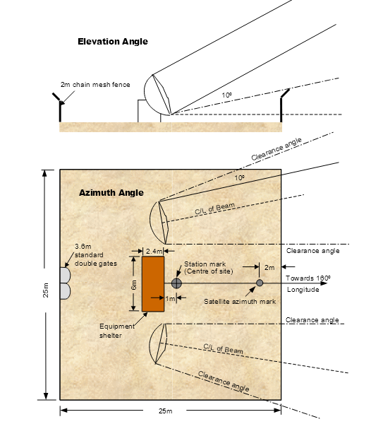
Figure 11.1‑1: Communications Satellite Ground Station Manned Centre Site
11.1.16.1 Where required, the provision of a ground earthing points must be made in agreement with the fuelling agent.
11.1.16.2 Where ground earthing points are provided, the resistance to earth must not exceed 10,000 ohms.
11.1.16.3 Where ground earthing points are provided, they must be maintained in accordance with the procedures set out in paragraphs 11.1.17.1 to 11.1.19.1.
Note: Civil Aviation Order Section 20.9 titled ‘Air Service Operations - Precautions in Refuelling, Engine and Radar Ground Operations’ also contains information on ground earthing points. |
11.1.17.1 Each ground earthing point must be tested for its electrical resistance, both as part of the initial installation (or any replacement), six months after the installation (or any replacement), and also thereafter as part of the Aerodrome Technical Inspection.
11.1.17.2 Where testing shows that the earthing points are sound, they must be marked with a 15 cm diameter circle, painted white.
11.1.18.1 The ground earthing points must be inspected as part of the quarterly technical inspection to ensure that:
(a) the ground earthing point is firmly connected to the earthing rod and seated on the pavement;
(b) the earthing rod is firmly embedded in the ground;
(c) the fins used for making electrical connections are free from dirt, grease paint, or any other substances; and
(d) no ground earthing points have been buried or removed.
11.1.19.1 When the resistance to earth exceeds 10,000 ohms and the ground earthing point cannot immediately be repaired or replaced, the head of the ground earthing point must either be removed or marked with a 15 cm diameter circle, painted red, to show it cannot be used.
11.1.20.1 Aircraft compass calibration may be conducted by using approved compass calibration equipment or by aligning an aircraft on known magnetic headings for the purpose of determining the degree of error in the magnetic compass, commonly referred to as ‘swinging the compass’. The latter method must only be conducted at a suitable compass swinging site.
Note: CAO 108.6 specifies the process control for the calibration of aircraft compasses. |
11.1.20.2 Guidance information for the establishment of a compass swinging site is provided in the Advisory Circular (AC).
11.1.21.1 The location and configuration of the Bureau of Meteorology (BoM) provided weather information station sites and their dial‑up phone numbers, and, as relevant, the VHF broadcast frequencies, are set out in the MET section of ERSA.
11.1.21.2 Current weather information from the site is also available by accessing the BoM internet site at: www.bom.gov.au.
11.1.22.1 Light aircraft tie-down facilities may be provided to secure aeroplanes against possible damage if they are blown off their apron parking position by strong winds.
11.1.22.2 Where provided, tie down facilities must be of adequate strength for the aircraft type being secured. The design of the tie-down facilities should be determined in consultation with an engineering consultant or manufacturer. The tie-down facilities should ideally be fixed to the ground using embedded anchors, and not left loose on the apron surface where they could create an FOD problem.
12.1.1.1 Unlike a certified aerodrome where the aerodrome operating procedures are regulated through an aerodrome manual, the procedures for a registered aerodrome are simpler.
12.1.1.2 The operator of a registered aerodrome is required to:
(a) Ensure that the aerodrome operational information which he or she has provided and published in ERSA and RDS is current;
(b) When it is not, promptly advise pilots, through the NOTAM system. of changes which may affect aircraft operations; and
(c) Submit to CASA an aerodrome safety inspection report conducted by an approved person, annually or at a timing as agreed by CASA.
12.1.1.3 To ensure that the aerodrome information provided is current, means that the aerodrome facilities must be maintained to the standard when the aerodrome was registered or if a facility is upgraded to a new standard, to that standard.
12.1.1.4 To be able to promptly advise changes, operators of registered aerodromes need to have personnel and procedures to conduct timely serviceability inspections, identify changed circumstances and make reports.
12.1.1.5 Although formal documentation of all facets of aerodrome operations are not required, it is in the interest of the operator of a registered aerodrome to be able to demonstrate that he or she is discharging the duty of care in providing a safe facility for aircraft operations. To avoid confusion and misunderstanding, all arrangements regarding aerodrome safety functions must be in writing.
12.1.1.6 If a registered aerodrome fails to meet safety requirements, CASA may suspend or cancel the registration. CASA Aerodrome Inspectors may conduct scheduled or unscheduled inspections of the aerodrome to assess whether a registered aerodrome is meeting safety requirements.
12.1.1.7 The standards and procedures of this Chapter are intended to assist operators of registered aerodromes to meet on-going aerodrome safety requirements.
12.1.2.1 The operator of a registered aerodrome must have in place, experienced or appropriately trained persons, known as reporting officers, to carry out the aerodrome safety functions. Attributes required include:
(a) Knowledge of the standards that the aerodrome has to be maintained to;
(b) Mature self-starter who can be relied on to conduct regular serviceability inspections of the safety elements of the aerodrome;
(c) Having the written and oral communication skills to initiate NOTAM or to communicate aerodrome condition status to ATC, pilots and other aerodrome users.
12.1.2.2 Reporting officers are normally directly under the employ of the operator of the aerodrome. However, at an aerodrome where aerodrome operator’s employees may not be available at all times, other persons may be nominated as reporting officers, for example the local agent of the airline during the period of regular public transport operations conducted by the airline concerned. Before entrusting the reporting function to a person, the aerodrome operator must ensure that the person is trained and has the appropriate attributes.
12.1.2.3 Reporting officers must be provided with appropriate radios in their vehicles so they can maintain a listening watch of aircraft activities on and in the vicinity of the aerodrome during working hours.
12.1.3.1 Aerodrome serviceability inspections are visual checks of elements of the aerodrome which may impact on aircraft safety. A checklist of contents of the inspection must be developed, commensurate with the size and complexity of the aerodrome.
12.1.3.2 The checklist must encompass at least the follow areas:
(a) Surface condition of the movement area, including cleanliness
(b) Surface condition of the runway, particularly the usability of unsealed pavements in wet conditions;
(c) Markings, markers, wind direction indicators and aerodrome lighting systems;
(d) any obstacles which may infringe the approach, take-off, transitional, inner horizontal or other surfaces nominated by the procedure designer;
(e) Animal or bird activities on and in the vicinity of the aerodrome;
(f) Check fences or other devices that prevent persons and vehicles getting on the movement area;
(g) Check currency of any outstanding NOTAM initiated.
Note: Elements of matters to be checked for are similar to those detailed in Chapter 10: Section 10.2. |
12.1.4.1 At an aerodrome with daily regular public transport operations, serviceability inspections must be carried out daily, preferably before the scheduled operations.
12.1.4.2 Additional serviceability inspections must be conducted after significant weather phenomena such as strong wind gust or heavy rain.
12.1.4.3 At an aerodrome without daily regular public transport operations, serviceability inspections may be reduced to before each regular public transport operation or not less than 2 per week, whichever is more.
12.1.5.1 The operator of a registered aerodrome must maintain an inspection logbook to demonstrate that inspections have been carried out. Beside recording the inspections, the logbook should also record significant aerodrome upgrading or remedial works.
12.1.5.2 The logbook must be kept for at least 12 months or the agreed period of the aerodrome safety inspection, whichever is longer. The logbook must be made available to a CASA Aerodrome Inspector conducting inspection of the aerodrome and to the qualified person who conducts the annual or periodic safety inspection.
12.1.6.1 Where a change in the aerodrome conditions requires a NOTAM to be issued this must be done in accordance with Section 10.3.
Note: A copy of Notification of Changes to Serviceability of a Registered Aerodrome to the NOTAM Office is shown in Section 12.2. |
12.1.6.2 Record of NOTAM initiated should be kept for at least a year or the agreed period of safety inspection, whichever is longer.
12.1.7.1 Aerodrome works must be arranged so as not to create any hazard to aircraft or confusion to pilots.
12.1.7.2 Aerodrome works may be carried out without closing the aerodrome provided safety precautions are adhered to.
12.1.7.3 Where aerodrome works are carried out without closing the aerodrome, the aerodrome works safety procedures specified in Chapter 10: Section 10.10 for certified aerodromes are equally applicable to registered aerodromes.
12.1.8.1 CASR Part 139 requires a registered aerodrome used by aircraft, with more than 9 passenger seats, to prepare and submit to CASA annually, or at a periodicity as agreed by CASA, a safety inspection of the aerodrome. Matters to be addressed in the report are also prescribed in the regulations.
12.1.8.2 The report must provide a true picture of the state of the aerodrome in its compliance with applicable standards. Where corrective action or necessary improvements are identified, the aerodrome operator must provide a statement of how the corrective action or improvements would be addressed.
12.1.8.3 For aerodromes used by aircraft with not more than 9 passenger seats, the approach and take-off area would still need to be checked on a regular basis, preferably at least once a year for tree growth or new tall objects. Where another obstacle may become the critical obstacle and affect the published take-off gradient or the threshold location, the checking should be conducted by a person with appropriate technical expertise, such as an approved person.
12.1.9.1 If the aerodrome is served by an instrument approach procedure, any obstacles, or proposed construction, that may infringe the obstacle limitation surface of the aerodrome, or other areas nominated by the designer of the instrument approach procedure, are to be reported to the designer.
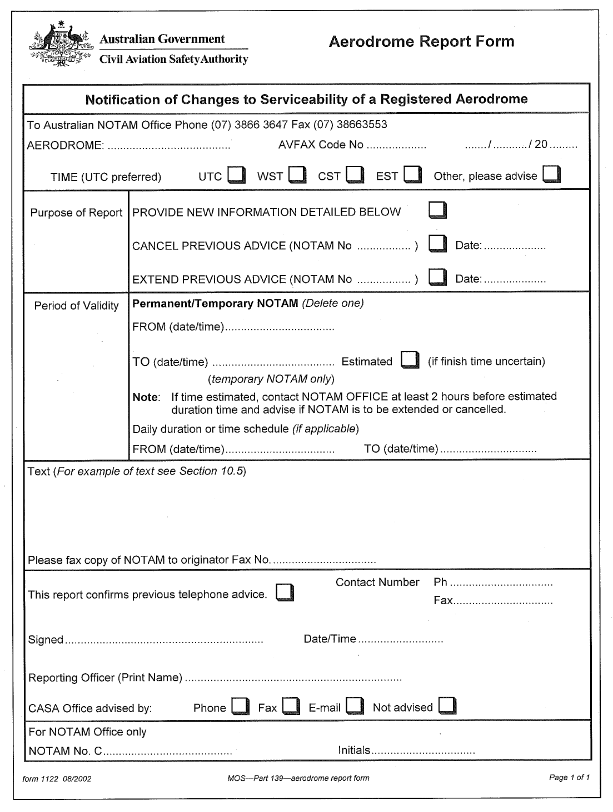
13.1.1.1 The Standards set out in this Chapter come into effect in accordance with paragraph 1.1.1.2B
13.1.1.1A This Chapter sets out the minimum Standards for aerodromes used in CASR Part 121B operations, that is air transport operations in aeroplanes with a maximum take-off weight not exceeding 5,700kg. Although these smaller aircraft may use aerodromes which meet the Standards applicable to aerodromes with respect to regular public transport operations by aeroplanes with a maximum take-off weight in excess of 5700kg, the minimum aerodrome standards for operations by such smaller aircraft are those set out in this Chapter.
13.1.1.2 Pursuance to CASR Part 121B, the responsibility of ensuring that an aerodrome is in compliance with CASR Part 139 standards rests with the holder of the AOC. This responsibility cannot be transferred even though some or all of the functions of the aerodrome may be delegated to another person, such as the owner or operator of the aerodrome.
13.1.1.3 Notwithstanding Paragraph 13.1.1.2, persons providing aerodrome facilities or services to aircraft operations have a duty of care to provide a safe facility or service. Unless an aerodrome is certified or registered, CASA does not regulate the operator of the aerodrome. However, activities of the aerodrome operator may be subject to CASA Inspector scrutiny as part of the audit of the AOC holder’s compliance with regulations.
13.1.2.1 The required physical dimensions and obstacle limitation surfaces (OLS) are set out in Table 13.1‑1.

Figure 13.1‑1: Obstacle limitation surfaces
Table 13.1‑1: Standards for physical dimensions and obstacle limitation surfaces
Runway and obstacle surfaces | Aeroplanes not exceeding 5,700kg by night | Aeroplanes not exceeding 5,700kg by day | Aeroplanes not exceeding 2,000kg by day |
Runway and strip | | | |
Runway width | 18 m | 15 m | 10 m |
Runway strip width: - preferred graded - minimum acceptable graded - graded plus ungraded | 80 m 45m 80m | 60 m 45m 60m | 30 m 60m |
Runway longitudinal slope | 2% | 2% | 2% |
Runway transverse slope | 2.5% | 2.5% | 2.5% |
Runway strip transverse slope | 3.0% | 3.0% | 3.0% |
Approach and take-off surfaces | | | |
Length of inner edge | 80 m | 60 m | 30 m |
Distance of inner edge before threshold | 60 m | 30 m | 30 m |
Divergence, each side | 10% | 10% | 10% |
Length of surface | 2500 m | 1600 m | 900 m |
Slope | 4% | 5% | 5% |
Transitional surface | | | |
Slope (to 45 m in height) | 20% | 20% | 20% |
Inner horizontal surface | | | |
Height | 45 m | 45 m | 45 m |
Radius from runway strip | 2,500 m | 2,000 m | 2,000 m |
Note: At aerodromes with 10m wide runways, the aircraft operator or pilot in command should take into account the effects of crosswind. |

Figure 13.1‑2: OLS cross-section
13.1.2.2 Obstacles. Where an aeroplane operation is affected by the presence of obstacles, the matter needs to be brought to the attention of the relevant CASA office, which will determine obstacle marking and lighting requirements and any operational limitations.
13.1.2.3 Runway length. The runway length requirement varies depending on aircraft type and local geography. It is necessary to ensure that the runway length provided is adequate for the most demanding aeroplane (not necessarily operating to maximum take-off weight) that the aerodrome is intended to serve.
13.1.2.3A Runway strip. The runway strip may consist of a graded portion and an ungraded portion in cases where it is impractical to grade the entire runway strip. The impracticability of complying with specified runway graded width requirements will depend on the circumstances of each individual case. Aerodrome operators should direct any questions about this issue to their nearest CASA area office.
13.1.2.4 Clearways and stopways. If a clearway or stopway is provided to supplement the runway length, it must be provided in accordance with the standards for clearways and stopways specified in Chapter 6.
13.1.3.1 Aerodrome markings or markers must be provided. Sealed surfaces are normally marked by paint markings and unsealed surfaces by markers.

Figure 13.1‑3: Aerodrome markings
13.1.3.2 For a sealed runway, the runway thresholds must be painted in accordance with Paragraph 8.3.8. A runway centreline marking is not required on runways which are 18 m wide or less. White painted runway side stripes, 0.3 m wide, should be provided if there is a lack of contrast between the runway surface and the surrounding area.
13.1.3.3 On unsealed runways, where the runway strip is not maintained to the normal runway grading standards, the runway must be marked using cone markers. Where both the runway and the runway strip are prepared suitable for aircraft operations, either the runway or the runway strip may be marked. Where the runway is not marked using cone markers, the threshold locations should be marked using white cones appropriately positioned in the shape of a └──┘.
Note: Where cone markers are used they may be held down using tent pegs or similar, provided the pegs do not pose a hazard to aircraft or compromise the frangibility of the marker. |
13.1.3.4 For both sealed and unsealed runways, the runway strip should also be marked by using cones, gable markers, tyres, or 200 litre drums cut in half along their length and placed with the open side down, or something similar. These runway strip markers should be white in colour.
Note: Runway cone markers should have a 0.4 m base diameter and be 0.3 m in height. Runway strip cone markers should have a 0.75 m base diameter and be 0.5 m in height. Gable markers should be 3 m in length. |
13.1.3.5 Cone or similar size markers need to be spaced not more than 90 m apart. Gable or similar size markers need to be spaced not more than 180 m apart.
13.1.3.6 Where the edges of unsealed taxiways or aprons might not be visually clear to pilots, markers may be provided in accordance with Section 8.2.
13.1.4.1 Where a runway is intended for night operations, the runway must be provided with runway edge lighting, spaced laterally at 30 – 31m apart, and longitudinally at approximately 90m apart. The edge lights on each side must present two parallel straight rows equidistant from the runway centreline. The lights indicating both ends of the runway must be at right angles to the runway centreline. See Figure 13.1-4 for a typical layout of runway lights.
13.1.4.2 Where there is no permanent electricity supply, the following may be used:
(a) lights producing white light and powered by portable generators, batteries, or similar power sources; or
(b) flares.
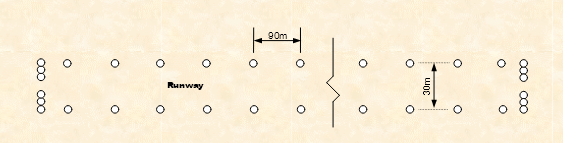
Figure 13.1‑4: Aerodrome lighting
13.1.5.1 The standard wind direction indicator is a tapering fabric sleeve (wind sock), 3.65 m long and white in colour. It must be located such that it is clearly visible from the air. It must also be located clear of the 1:5 (20%) transitional surface.
13.1.5.2 If the aerodrome is intended for night operations, the wind direction indicator must be provided with illumination.
13.1.5.3 To enhance sighting of the wind direction indicator from the air, the wind direction indicator must be located within a circular area 15 m in diameter, appropriately blackened or provided with a contrasting colour, and bounded by 15 equally spaced white markers.
13.1.6.1 A ground signal area, consisting of a circle, blackened or provided with contrasting colour of 9 m in diameter marked by 6 equally spaced white markers must be provided near the wind direction indicator for the purpose of displaying ground signals to pilots.
13.1.6.2 Marking of unserviceability of aerodrome. A white cross with each arm 6 m in length and 0.9 m in width must be displayed on the signal circle when the aerodrome is closed to aircraft operations.

Figure 13.1‑5: Total unserviceability marking
13.1.7.1 The surface of the runway and runway strip need to be maintained to minimise adverse effects on aeroplane operations, as follows:
Table 13.1‑2
Surface | Runway | Runway strip |
Sealed surface | After compaction, the surface is to be swept clean of loose stones | N/A |
Height of grass | | |
Sparse | 450 mm | 600 mm |
Medium | 300 mm | 450 mm |
Dense | 150 mm | 300 mm |
Size of loose stones | | |
Isolated stones on natural surface | 25 mm | 50 mm |
Constructed gravel surface | 50 mm | 75 mm |
Surface cracks | 40 mm | 75 mm |
13.1.7.2 The surface of the unsealed runway must not have irregularities, which would adversely affect the take-off and landing of an aircraft.
Note: An empirical test for runway riding quality is to drive a stiffly sprung vehicle such as a medium size utility or unladen truck along the runway at not less than 65 kph. If the ride is uncomfortable, then the surface needs to be graded and levelled. |
13.1.8.1 If the aerodrome is not provided with an Airservices Australia NOTAM service, the AOC holder needs to establish, in concert with the aerodrome operator, a reporting system such that the pilot can be notified of any changes to the aerodrome serviceability status, preferably before embarking on the journey.
13.1.8.2 The aerodrome operator has a duty of care to provide information that is as accurate as possible. This would require physical inspection of the aerodrome, ideally before the departure of the airline’s aeroplane from its base aerodrome, but always before the arrival of the aeroplane. To maintain the accuracy of the aerodrome serviceability status, it is essential that the aerodrome be inspected after strong wind or rain. The information provided should include:
(a) runway surface condition: dry, wet, soft, or slippery;
(b) runway strip condition: any obstruction, undue roughness, visibility of markers;
(c) wind direction indicator: if torn or obstructed;
(d) approach and take-off areas: if there are objects close to or above the obstacle surfaces;
(e) other hazardous condition or object known to the aerodrome operator, e.g. animal or bird hazard.
13.1.8.3 If the aerodrome is not published in AIP-ERSA, the AOC holder’s Operations Manual should indicate clearly the aerodrome operator’s contact details for serviceability status reports.
Note: It is important that the person performing the inspection and reporting duties has a working knowledge of the aerodrome safety requirements and understands clearly his or her responsibilities. |
13.1.8.4 For unsealed landing areas, serviceability is often affected by rain. Where the aerodrome is deemed too wet for aeroplane operations, the aerodrome operator needs to display the unserviceability signal, and notify the airlines accordingly. When in doubt, always err on the side of safety.
14.1.1.1 Subpart F of CASR Part 139 prescribes the provision of certain types of radio communication facilities at particular aerodromes for the purpose of enhancing the safety of air navigation. The radio communication facility required may be either a Certified Air/Ground Radio Service or a Frequency Confirmation System.
14.1.1.2 This Chapter specifies the requirements and the standards for the provision of the above two types of radio communication services.
14.1.2.1 When the following terms or abbreviations are used in this Chapter, they have the meaning given:
AAIS: Automatic Aerodrome Information Service means a service that provides current, routine information to aircraft arriving at or departing from an aerodrome by means of repetitive broadcasts on a discrete frequency.
AFRU: Aerodrome Frequency Response Unit.
Certified Air/Ground Radio Operator (CA/GRO): A person certificated under regulation 139.430 as a CA/GRO.
CTAF: Common Traffic Advisory Frequency
Frequency Confirmation System means a ground radio system for an aerodrome that, if it receives a transmission from an aircraft on the MBZ frequency or the CTAF for the aerodrome, sends a signal or message to the aircraft confirming that the transmission has been received.
MBZ: Mandatory Broadcast Zone
Relevant Traffic: Aircraft that the CA/GRO knows to be operating within the MBZ and that may constitute a hazard to a broadcasting aircraft.
VHF: Very High Frequency
14.2.1.1 To perform the functions of a CA/GRO, the operator must hold a CA/GRO certificate issued by CASA (CASA Form 716).
14.2.2.1 The primary purpose of a CA/GRS is to enhance the safety of air transport aircraft operations by the provision of relevant traffic information. This aspect of the service requires CA/GROs to have had specialised training and experience. Therefore, applicants for the issue of a CA/GRO Certificate must hold, or have held within the last ten years, an ICAO recognised Air Traffic Controller licence or an Australian Flight Service Officer licence.
14.2.2.2 The application form for a CA/GRO certificate is CASA Form 715. Completed application forms should be sent to the CASA Area Office (attention Licensing Officer) closest to the applicant’s place of residence.
14.2.2.3 After receiving an application, before issuing a CA/GRO certificate, CASA must:
(a) confirm the applicant’s identity; and
(b) confirm that the applicant meets the appropriate pre-requisite licence qualification.
14.2.2.4 If the applicant meets the licence qualification, CASA will issue the applicant with a Certified Air/Ground Radio Operator Certificate (CASA Form 716).
14.2.2.5 A CA/GRO Certificate is valid for 10 years from the date of issue.
14.2.3.1 A CA/GRS must provide the following services to aircraft within airspace designated as an MBZ area in which the aerodrome is located:
(a) advice of relevant air traffic in the MBZ airspace or on the aerodrome;
(b) aerodrome weather and operational information, including:
(i) wind speed and direction;
(ii) the runway preferred by wind or noise abatement requirements;
(iii) runway surface conditions;
(iv) QNH;
(v) temperature;
(vi) cloud base and visibility;
(vii) present weather;
(viii) other operational information;
(ix) for departing aircraft, a time check;
(x) call-out of the aerodrome emergency services;
(xi) provide aerodrome information to pilots who telephone the service.
14.2.3.2 A CA/GRO may also provide other information requested by pilots.
14.2.3.3 The decision to use, or not to use, information provided by a CA/GRO rests with the pilot in command.
14.2.3.4 A permanent CA/GRS must be provided with the following facilities and documentation:
(a) a suitable work area that provides the operator with a full view of the manoeuvring area and circuit area;
(b) two-way VHF radio communications;
(c) an AAIS;
(d) a telephone;
(e) a means of receiving NOTAM;
(f) instrumentation that meets Bureau of Meteorology and ICAO Annex 3 standards for aviation use, to provide the following meteorological information:
(i) wind direction and speed (2 minute averaging); Instrumentation measurement accuracy to be: Direction ±5 degrees; Speed ±1 kt up to 20 kt; = ±5% above 20 kt.
(ii) QNH (measured to within 0.1 hPa and rounded down to the next whole integer; eg 1010.9 hPa is reported as 1010 hPa;
(iii) air temperature (measured to within 0.5 degrees Celsius and rounded up to the next whole degree Celsius e.g. 12.5 degrees C is reported as 13 degrees C.
(g) current aeronautical documentation, NOTAM, and charts appropriate to IFR and VFR operations within the MBZ;
(h) the Aerodrome Emergency Plan (AEP) for the aerodrome.
14.2.3.5 A CA/GRO must use the standard aviation communication techniques and phraseology set out in AIP.
14.2.3.6 A CA/GRS call-sign will be the location name of the aerodrome followed by the word ‘Radio’.
14.2.3.7 The aerodrome operator must provide NOTAM advice to AIS of the establishment of, or any changes to, a CA/GRS.
14.2.4.1 Aerodrome Information must be broadcast on the AAIS in the following order:
- preferred runway
- wind direction and speed
- runway surface conditions
- QNH
- temperature
- cloud base and visibility
- present weather or CAVOK
- aerodrome operational information
14.3.1.1 At all non-controlled aerodromes located in an MBZ, and at those non‑controlled aerodromes in CTAF areas which are used not less than 5 times per week by aircraft engaged in air transport operations that have a maximum passenger seating capacity greater than nine, a ground-based frequency confirmation system is required. This requirement may be practically satisfied by one of the following facilities:
(a) a certified air/ground radio service (CA/GRS); or
(b) an aerodrome frequency response unit (AFRU); or
(c) a Unicom service.
14.3.2.1 The AFRU is an electronic, ground based, aviation safety enhancement device, intended for use on the CTAF or MBZ frequency at non-controlled aerodromes. It is essentially an internally controlled VHF transceiver with a pre-recorded message transmission capability. AFRU transmissions are triggered when the AFRU receiver detects aircraft transmissions on the correct aerodrome frequency. This response capability is intended to reduce the incidence of incorrect VHF radio frequency channel selection by pilots. If the pilot is aware of the presence of an AFRU in a CTAF area or MBZ, the AFRU will assist in alerting pilots to these situations by providing an automatic transmission on the aerodrome frequency to confirm the receipt of a transmission by an aircraft within radio range. The confirming AFRU transmission will be either a short pre-recorded voice message (e.g. aerodrome name followed by MBZ or CTAF (as relevant), or a short (300 millisecond) tone burst, depending upon radio transmission activity by aircraft operating on that frequency in the preceding 5 minutes, and the form of the pilot’s transmission to the AFRU.
14.3.2.2 An AFRU may also have an optional facility incorporated to operate the runway lights during hours of reduced light and darkness.
14.3.3.1 The AFRU will be suitable for installation at non-controlled aerodromes. It may also be utilised at those aerodromes which are controlled during busier traffic hours, and which become an MBZ after hours during control tower closure. (In this latter role, the AFRU must only be activated during the hours when the tower is closed; for that purpose the AFRU must have a remote activation capability).
14.3.4.1 When an aircraft operating in radio range of the AFRU makes a transmission (radio broadcast or unmodulated carrier burst) on the aerodrome frequency, the AFRU must be able to detect the presence of aircraft VHF carrier transmissions of 2 seconds or more in duration, and, at the end of the aircraft transmission, it must automatically respond with either one of the following types of transmissions on that frequency:
(a) A pre-recorded short voice message, (normally taking the form of the aerodrome location) if there has been no other received aircraft transmissions in the previous 5 minutes; or
(b) A short (300 ms) tone burst if any aircraft transmissions have been received in the previous 5 minutes.
14.3.4.2 In addition, the AFRU must also be able to detect and respond to any aircraft transmissions which consist of three sequential carrier bursts over a five second period, with the pre-recorded voice message as at (a) above, regardless of radio transmission activity by aircraft in the last 5 minutes.
14.3.5.1 Australian Communications Authority (ACA) Type Approval: Units must meet the technical requirements of, and be certified as complying with, the Australian Communications Authority Equipment Compliance Requirement ECR 203A for Amplitude Modulated Transmitter/Receivers (Base and Mobile) for 25 kHz Carrier Frequency Separation in the Aeronautical Frequency Band 118 - 137 MHz.
14.3.5.2 Frequency Coverage: 118.000 – 136.975 MHz
14.3.5.3 Frequency Selection: Front panel pre-selectable channels for receiver and transmitter with frequency readout of each channel. All frequencies in the range to be selectable in 25 kHz steps.
14.3.5.4 Channel Separation: 25 kHz.
14.3.5.5 Modulation: Amplitude Modulation; depth of modulation to be set at 85% for voice transmissions; 10% for tone burst transmissions.
14.3.5.6 Operating Temperature Range: -10 to +65 degrees Centigrade.
14.3.5.7 Carrier Frequency Stability: Better than or equal to 0.002%.
14.3.5.8 Receiver Sensitivity: S/N ratio > 10 dB for input signal of 2 μV (-101 dBm). Receiver sensitivity to be adjustable between 2 μV and 5 μV.
14.3.5.9 Receiver Selectivity: Unit to operate satisfactorily for all received carrier frequencies within 0.005% of any selected frequency.
14.3.5.10 Transmitter Radiated Power Output: Minimum 2 watts ERP, adjustable to achieve 75 μV/m (-109 dBW/m2) field strength at the limit of the required coverage area (20 NM line of sight). Maximum power output shall not exceed 5 watts ERP.
14.3.5.11 RF Polarisation: Vertical.
14.3.5.12 Transmitter Recorded Voice Message: 8 seconds minimum capacity. Audio transmissions to be clear and intelligible. Length of carrier transmission not to exceed the recorded voice message time, i.e. carrier must not continue after the voice modulation ceases.
14.3.5.13 Annunciation Timing: The timing of the commencement of the transmitted recorded voice message or the tone burst is to be less than 0.5 second after the end of the aircraft transmission.
14.3.5.14 Transmitter Beepback Tone: 1000 Hz, 300 millisecond tone burst.
14.3.5.15 Power Supply: 220–240 V AC 50 Hz power source shall automatically changeover to internal or external battery stand-by power capable of operating the unit without interruption for 24 hours assuming the load is two voice responses per hour during the 24 hour period.
14.3.5.16 Fault Detection/Timeout and Alarm: In the event of an internal fault condition that results in continuous (jammed) transmission of the VHF carrier, the unit shall internally detect the continuous transmission within one minute and shut down or recycle the unit. Front-panel mounted alarm readout shall provide notification of this fault condition. Indication of the presence or failure of AC mains power, and changeover to operation on the stand-by battery, shall also be clearly provided by front panel indicators. (If an external power supply is used, the indication may be located on the power supply).
14.3.5.17 Remote Activation: The unit shall be capable of remote activation by an external control function such as a timing device. The external function shall be connected via socket connection. The stand-by batteries of the unit shall remain fully charged during the time that the unit remains remotely activated.
14.3.5.18 Reliability: Design reliability level of the unit shall be in keeping with its safety enhancement function. Design MTBF is to be a minimum of 10000 hours. The AFRU shall consist entirely of solid-state components, with the exception of switching relays (if any).
14.3.5.19 Maintainability: The unit shall be constructed so that fault restoration can be carried out in the field by module/circuit card replacement. Design MTTR shall be less than 72 hours.
14.3.5.20 Construction: Units shall be robustly constructed for either rack mounting, panel mounting or stand-alone bench mounting. All status indicators shall be front panel mounted. Controls, adjustments (other than pre-set adjustments), recording controls, frequency selectors, etc. shall be accessible. Frequency selectors shall clearly indicate the frequency selected and be set up so that it is not possible to inadvertently change frequency by a person brushing past the unit.
14.3.5.21 Mains Connection Approval: Units shall be approved for connection to single-phase 240 VAC power supply by an Australian electrical supply authority. (This does not apply if units are powered by DC sourced from a separate power supply).
14.3.5.22 Installation, Operation and Maintenance Handbook: Each unit shall have an accompanying Handbook which provides clear instructions covering all aspects of the Installation, Operation, Routine Maintenance, and Fault Finding requirements. The Operation section of the handbook shall consist of step-by-step instructions.
14.3.5.23 Maintenance: Aerodrome operators are required to carry out routine maintenance of the AFRU in accordance with the maintenance instructions in the Installation, Operation and Maintenance Handbook.
Note: See Section 9.3 for standards for PAL. |
14.3.6.1 Optional Additional AFRU Function - Pilot-Activated Lighting Control: Optional additional functionality may be provided with the AFRU unit to provide for aircraft actuated operation of the aerodrome lights at the aerodrome at which the AFRU is located, during night hours or other times of low natural light levels. This option shall emulate the function of the existing PAL circuitry, but permit operation on the CTAF or MBZ frequency.
14.3.6.2 The Pilot Activated Lighting (PAL) option includes a light sensor mounted remotely from the AFRU. During the time the light sensor detects that the natural light intensity is less than a preset level (adjustable on the AFRU unit), and on receipt of an aircraft transmission of three carrier bursts (three PTT clicks) over a five-second period, the AFRU will provide separate relay outputs to operate the airport lighting circuitry (runway lights and illumination of the wind indicator) at the aerodrome. The AFRU will then transmit the standard reply of the normal pre-recorded voice message (the aerodrome name and MBZ or CTAF), followed by the additional recorded voice message of “runway lights on”. The runway lights will operate for a period of either 30 minutes or 60 minutes. The operating period of either 30 minutes or 60 minutes will be preset within the unit. Ten (10) minutes prior to the end of the 30 or 60 minutes period, the windsock light will flash at 1 second intervals and the MBZ/CTAF response, followed by the announcement "runway lights 10 minutes remaining" will be broadcast. At any time during the period of time that the lights are operated, receipt of a further transmission of three carrier bursts shall reset the timing period back to either 30 or 60 minutes.
14.3.7.1 Fail-safe Relay Output Switching of Runway and Windsock: Fail-safe switching of runway and windsock outputs to be provided. Outputs to be relay controlled, +12 VDC, for driving remote lighting circuits. (Other configurations to match aerodrome lighting circuitry are permissible, but must be fail-safe, i.e. in the event of failure of the AFRU, the aerodrome lights will be actuated and remain actuated).
14.3.7.2 Ambient Light Sensor: The ambient light sensor device is to be infinitely adjustable from full darkness to bright daylight. Preset control to be located in the AFRU unit, or in the sensor housing.
14.3.7.3 Operation: The PAL output will activate on receipt of 3 correct PTT bursts (as per standard AFRU). If ‘dark’ =< pre-set darkness level, the normal MBZ/CTAF response message will be transmitted, followed by one of two messages: “runway lights on" message if the lights are activated, or “no runway lights”, depending on whether or not lights have actually illuminated. This is to be sensed in the AFRU by a signal output by a current transducer in the lighting circuitry, and shall only confirm lights on if the runway lighting system is drawing current.
14.3.7.4 Timing: Timings shall emulate the existing PAL system in use, i.e. 30 or 60 minutes preset for lights on, windsock lighting flashes at 1 second rate for the last 10 minutes, and shall be microprocessor controlled within the AFRU unit. Timings to be internally preset. Timer countdown to recommence on receipt of further transmission of 3 PTT bursts during the period that the lights are in operation.
14.3.8.1 A flight check of the AFRU and the optional PAL function shall be to the satisfaction of a CASA inspector. The flight test will ensure the functionality of the AFRU and optional PAL at appropriate points on the aerodrome and out to the limits of the relevant CTAF area or MBZ area.
14.3.8.2 On the ground:
(a) check activation of AFRU and PAL from the parking apron(s) of the aerodrome.
(b) check all specified functionality of the AFRU and PAL option.
14.3.8.3 In the air:
(a) check proper performance of AFRU at line of sight distances out to 20 NM radius of the aerodrome at altitudes of 3,000 to 5,000 feet AGL.
(b) check that AFRU Receiver sensitivity and Transmitter power levels are adjusted to ensure that the AFRU does not activate, and does not transmit, beyond approx 30 NM radius.
(c) check that voice and tone responses are clear and legible. Check that three microphone clicks of 1 second ON, 1 second OFF within 5 second period will activate voice response. (Tolerance on 1 second ON or OFF is 0.5 seconds).
(d) ensure that the AFRU does not trigger falsely during aircraft transmissions. Ensure that no interruptions occur to aircraft transmissions by false triggering of the AFRU during the aircraft transmission.
(e) check and ensure proper operation of the PAL option as follows:
(i) ensure lights are activated by three microphone clicks at a radius of 15 NM in line-of-sight from the aerodrome, to altitudes of 3,000 to 5,000 feet AGL.
(ii) ensure that lights remain activated for either 30 minute or 60 minute preset period after activation.
(iii) ensure receipt of correct recorded voice responses after activation.
(iv) ensure that illuminated wind indicator flashes 10 minutes before the completion of the 30 or 60 minute period of operation of the lights.
(v) ensure that lights are reset for the preset 30 or 60 minutes period following an aircraft transmission of three microphone clicks at any time within the preset 30 or 60 minutes period.
14.4.1.1 Unicom (Universal Communications) services are non-ATS radio communication services provided on an MBZ frequency or CTAF to enhance the value of information normally available about a non-controlled aerodrome. A Unicom service is not a Certified Air/Ground Radio Service.
14.4.1.2 The primary function of the frequencies (MBZ/CTAF) used for Unicom services is to provide the means for pilots to exchange traffic information for separation purposes. Unicom services, being a secondary use of these frequencies, must not inhibit the exchange of aircraft to aircraft traffic information.
14.4.1.3 Participation in Unicom services by an aerodrome operator, whether for the purposes of a frequency confirmation system or otherwise, is to be limited to the exchange of radio messages concerning:
(a) confirmation of the CTAF/MBZ frequency selected by aircraft;
(b) general aerodrome weather reports;
(c) aerodrome information;
(d) estimated times of arrival and departure;
(e) passenger requirements;
(f) aircraft refuelling arrangements;
(g) maintenance and servicing of aircraft including the ordering of urgently required parts;
(h) unscheduled landings by aircraft.
14.4.1.4 General aerodrome weather reports provided by a Unicom operator are to be limited to simple, factual statements about the weather, unless the Unicom operator is authorised by CASA to make meteorological observations.

| Aerodrome Report Form |
Notification of Changes to Serviceability of a Certified/Registered Aerodrome | |
To Australian NOTAM Office Phone (07) 3866 3647 Fax (07) 38663553 | |
AERODROME: ................. | AVFAX Code No ........ | / / 20 ....... | |
TIME (UTC preferred) UTC WST CST EST Other, please advise | |
Purpose of Report | PROVIDE NEW INFORMATION DETAILED BELOW | |
| CANCEL PREVIOUS ADVICE (NOTAM No ....... ) Date: ......... | |
| EXTEND PREVIOUS ADVICE (NOTAM No ....... ) Date: ......... | |
Period of Validity | Permanent/Temporary NOTAM (Delete one) | |
| FROM (date/time) ............... | |
| TO (date/time) .................. Estimated (if finish time uncertain) (temporary NOTAM only) | |
| Note: If time estimated, contact NOTAM OFFICE at least 2 hours before estimated duration time and advise if NOTAM is to be extended or cancelled. | |
| Daily duration or time schedule (if applicable) | |
| FROM (date/time) ............... | TO (date/time) .............. | |
Text (For example of text see Section 10.5) | |
| |
Please fax copy of NOTAM to originator Fax No. .............. | |
This report confirms previous telephone advice. | Contact Number | Ph .............. Fax .............. | |
| |
Signed ............................ | Date/Time ............ | |
| |
Reporting Officer (Print Name) ............................... | |
CASA Office advised by: Phone Fax E-mail Not advised | |
For NOTAM Office only | |
NOTAM No. C .................. | Initials .............. | |
The Federal Government TimeSaver initiative aims to assess the time taken to complete Government Forms. Please indicate the approximate time taken to complete this form. | | Hrs | | Mins |
| | | | | | | | | | | | | |

| Application for an Aerodrome Certificate |
1. Particulars of the Applicant |
|
|
|
|
2. Particulars of the Aerodrome
Name of aerodrome: ................................................................ |
Real property description: ............................................................ ............................................................................ |
Geographical coordinates of the ARP: Lat:.................... Long: .................... |
Bearing and distance from nearest town or populous area: .................................... ................................................................................ |
3. Is the Applicant the Owner of the Aerodrome Site? Yes (Go to Item 4) No |
If the applicant is Not the owner of the site, provide: a) Details of rights held in relation to the site; and b) Name and address of the owner of the site and written evidence to show that permission has been obtained for the site to be used by the applicant as an aerodrome. | |
4. Indicate the Largest Type of Aircraft Expected to Use the Aerodrome |
................................................................................ ................................................................................ |
5. Is the Aerodrome to be Used for Air Transport Operations? Yes No |
6. Details to be shown on the Aerodrome Certificate |
Aerodrome name: .................................................................. Aerodrome operator:................................................................ |
|
On behalf of the Aerodrome Operator shown above, {Delete if not applicable}. I hereby apply for a certificate to operate the aerodrome. Signed: ............................................ My authority to act on behalf of the applicant is: ............................................................................ ............................................................................ ............................................................................ Name of person making the declaration: ................................................. Date: ...../...../..... |
Notes: 1. Two copies of the Aerodrome Manual, prepared in accordance with the regulations and commensurate with the aircraft activities expected at the aerodrome, are required as part of the application. 2. The application should be submitted to the nearest CASA Office. 3. A quote will be provided for the cost of processing this application. CASA will take no action to assess this application until payment is received. 4. Documentary evidence in support of all matters in this application may be requested. |
The Federal Government TimeSaver initiative aims to assess the time taken to complete Government Forms. Please indicate the approximate time taken to complete this form. | | Hrs | | Mins |
| | | | | |

| Application to Register an Aerodrome |
1. Particulars of the Applicant |
|
|
|
|
2. Particulars of the Aerodrome
Name of aerodrome: ................................................................ |
Real property description: ............................................................ ............................................................................ |
............................................................................ |
Bearing or distance from nearest town or populous area: ..................................... ................................................................................ |
3. Is the Applicant the Owner of the Aerodrome Site? Yes (Go to Item 4) No |
If the applicant is Not the owner of the site, provide: a) Details of rights held in relation to the site; and b) Name and address of the owner of the site and written evidence to show that permission has been obtained for the site to be used by the applicant as an aerodrome. | |
4. Indicate the Largest Type of Aircraft Expected to Use the Aerodrome |
................................................................................ ................................................................................ |
5. Is the Aerodrome to be Used for RPT/Air Transport Operations? Yes No |
On behalf of the Aerodrome Operator shown above, {Delete if not applicable}. I hereby apply for registration of the aerodrome. Signed: ............................................ My authority to act on behalf of the applicant is: ............................................................................ ............................................................................ Name of person making the declaration: .............................................. Date: ...../...../..... |
 6. Aerodrome Data If not applicable, insert N/A in the box on the right: 6. Aerodrome Data If not applicable, insert N/A in the box on the right:
(To be completed by an approved person as prescribed in CASR 139. Aerodrome Data must be derived in accordance with Manual of Standards Part 139 – Aerodromes, Chapter 5: Aerodrome Information for AIP.) |
| |
Note: Application must be accompanied by a report prepared by an approved person as prescribed in CASR 139, confirming that the information provided overleaf is accurate and that the aerodrome meets the applicable safety standards. See page 2.
Report on Aerodrome Data by Approved Person (as Prescribed in CASR 139)
6a. Aerodrome Diagram
6b. Aerodrome Location: (ARP) Lat:.................... Long: ...................
6c. Aerodrome Administration (Provide the following information on the aerodrome owner.)
Name of Aerodrome:.................................................................. Name of Aerodrome Operator: .......................................................... |
Address: .......................................................................... .................................................................................. Tel: B/H.....................(A/H) ...................... Fax ...................... |
State in which the Aerodrome is Located:................................................... Is this Aerodrome Open to Public? No Yes Are there Landing Charges? No Yes Applicable Charges:....................... .................................................................................. If open to the public, who is (are) the Aerodrome Reporting Officer(s)? Name: ...........................B/H ...................(A/H)...................... Name: ...........................B/H ...................(A/H)...................... |
6d. Runway Details (For each runway, provide the following. Add a page if there is more than one runway.)
Runway Designation:...................... Runway Reference Code: ................... Runway End:.....TORA: .........TODA: .......... (…...%) ASDA: .......... LDA: ......... Runway End:.....TORA: .........TODA: .......... (…...%) ASDA: .......... LDA: ......... Runway Width: .....Runway Slope:........Runway Strip Width (graded): ..........(overall):....... STODA: Runway End:....1.6%.........1.9%......2.2%......2.5%......3.3%......5.0%........ Runway End:....1.6%.........1.9%......2.2%......2.5%......3.3%......5.0%........ Pavement Surface Type:............. Pavement Rating:.........................(ACN/PCN) or Maximum Aircraft Weight.............and Tyre Pressure......................able to use runway. |
6e. Aerodrome Lighting: .......................(For each runway equipped with lighting, provide the following. Add extra pages if there is more than one runway with lighting.)
Runway Designation:.......................... Light Intensity: Low Medium High Approach Lighting Provided: Yes No Pilot Activated Lighting (PAL) Provided: Yes No Frequency:............................ T-VASIS or PAPI Provided: Yes No Type and Location:....................... Aerodrome Beacon Provided: Yes No Type and Location:....................... Standby Power Provided: Yes No Type:................................. Portable Lights: Yes No Any other lighting, specify:.............................................................. |
6f. Ground Services (Provide the following information on services available to pilots.)
Fuel Type: ............Supplier: .................................... Tel: (B/H).............(A/H).................. Met Facilities Available: Yes No CTAF or MBZ available: Yes No CTAF: ............ MBZ: ............. UNICOM: ............... AFRU: .............. Navaid Facilities Available: Yes No ATS Communication Facilities Available: Yes No Passenger Facilities Available: Yes No |
6g. Special Procedures: (Provide the following information about any special procedures that pilots need to observe or follow.) |
Special Procedures Apply: Yes No .................................................................................. .................................................................................. |
6h. Notices: (Provide the following information on any local safety information.) |
Details of any Obstacles:............................................................... .................................................................................. Details of any Hazards (eg, birds or animals):................................................ .................................................................................. .................................................................................. Details of any Restrictions on the use of Taxiways or Aprons:..................................... .................................................................................. Details of any other activities at the aerodrome (eg, sport aviation activities):.......................... .................................................................................. |
|
Approved person’s signature.............................. Date......../....../....... |
The Federal Government TimeSaver initiative aims to assess the time taken to complete Government Forms. Please indicate the approximate time taken to complete this form. | | Hrs | | Mins |
Notes to Manual of Standards Part 139
Note 1
The Manual of Standards Part 139 (in force under the Civil Aviation Safety Regulations 1998) as shown in this compilation comprises Manual of Standards Part 139 amended as indicated in the Tables below.
Table of Manual of Standards and Amendments
Year and
number | Date of notification
in Gazette/date of making/
date of registration on FRLI | Date of
commencement | Application, saving or
transitional provisions |
MOS 139 | 1 May 2003 | 1 May 2003 | |
MOS 139 Amendment (CASA 390/04) | FRLI 9 May 2005 (see F2005B01530) | 1 September 2004 | — |
MOS 139 2008 Amendment No. 1 | FRLI 9 January 2008 (see F2008L00088) | 10 January 2008 (see s. 2) | — |
MOS 139 2008 Amendment No. 2 | FRLI 15 April 2008 (see F2008L01090) | 16 April 2008 (see s. 2) | — |
MOS 139 2010 Amendment No. 1 | FRLI 12 May 2010 (see F2010L01202) | 13 May 2010 (see s. 2) | — |
MOS 139 2011 Amendment No. 1 | FRLI 29 April 2011 (see F2011L00657) | Ss. 1–3 and Schedule 1: 02 June 2011 Schedule 2: 17 November 2011 | — |
Revision History
Version | Date | Chapter/ Section/ Paragraph | Details |
1.7 | November 2011 | 5.1.2.5 | Substituted by 5.1.2.5 and 5.1.2.5A |
| After paragraph 5.1.2.10 | 5.2.1.11 added |
| | Section 10.17 | Substituted |
| | After Section 10.18 | Section 10.19 added |
1.6 | June 2011 | 1.2 | Definitions for Instrument Runway and Runway Visual Range (RVR) substituted |
| | Definitions for Low visibility procedures, Runway visibility (RV), and Visibility marker added |
| | After 6.2.24.2 | New 6.2.24.3 and a note added |
| | After 6.2.28.1 | Note added |
| | After 6.2.34.1 | Note added |
| | After 6.3.15.1 | Note added |
| | 6.3.17.1, Table 6.3-5, after the second Note | Note 3 added |
| | 6.4.4.2 | Omitted |
1.6 contd | June 2011 | 6.4.4.2, Table 6.4-1, Column 4, Precision Category I | Substituted |
| | 6.4.4.2, Table 6.4-1, Column 5, Precision Category II or III | Substituted |
| | 6.4.4.2, Table 6.4-1, after footnote d | Footnotes e and f added. |
| | After 7.2.3 | Subsection 7.2.4 inserted |
| | 8.3.7 | Subsections 8.3.7 and 8.3.7A substituted |
| | 9.1.1.1 (d) | Subparagraphs (d) and (e) substituted |
| | 9.1.11.1, the Note | Note substituted |
| | After 9.1.14.9A | Note inserted |
| | 9.7.2 | Substituted |
| | 9.7.3 | Substituted |
| | 9.10.18.1 (a) | Text substituted |
| | After 9.10.25.1 | Note inserted |
| | 9.10.25.2 | Omitted |
| | 9.13.11.2 (a) | Substituted |
| | After 9.19.3 | Subsection 9.19.4 inserted |
| | 9.20.2.5 (d) and the Note | Subparagraphs (d) - (g) and a note substituted |
| | After subsection 11.1.4 | A note and new subsection 11.1.4A inserted |
| | 11.1.8 | Substituted |
| | 11.1.9 | Substituted |
| | 11.1.10 | Substituted |
| | 11.1.11 | Substituted |
1.5 | May 2010 | 1.2 | Definition of Visibility changed |
| | 9.1.1.2 (c) (i) | Substituted |
| | 9.1.1.2 (c) (iii), (iv) and Notes | Inserted |
| | 9.1.1.2 (d) | Changed |
| | 9.1.2.2A and Note | Inserted |
| | 9.1.4.1 (ab) | Inserted |
| | 9.1.4.1 (c) | Note deleted |
| | 9.1.5.3 | Note inserted |
| | 9.1.6.1 | Note inserted |
| | 9.1.7.4 | Inserted |
| | 9.1.8.2 and 9.1.8.3 | Inserted |
| | 9.1.10 | Substituted |
| | 9.1.11.1 | Note substituted |
| | 9.1.12.6 and Note | Inserted |
| | 9.1.14.9 | Substituted and 9.1.14.9A added |
| | 9.1.15.1 (a) | Substituted |
| | 9.1.15.2A | Inserted |
| | 9.1.15.8 | Note deleted |
1.5 contd | May 2010 | 9.1.15.9 and 9.1.15.10 | Inserted |
| | 9.3.1 | Note inserted |
| | 9.3.1.2 (f) and Note | Inserted |
| | 9.4.3.4A | Inserted |
| | Figure 9.4-1 | Substituted |
| | 9.4.10.3 | Substituted |
| | 9.4.10.3A | Inserted |
| | 9.6.1.1 | Note inserted |
| | 9.6.1.3 | Substituted and 9.6.1.3A to 9.6.1.3C added |
| | 9.6.1.4 and Note | Substituted |
| | 9.9.1.10 | Deleted |
| | Figure 9.9-6 Key | METH changed to MEHT |
| | 9.10.11.3 | Substituted |
| | 9.10.11.6 | Inserted |
| | 9.10.17.1 (c) | Substituted |
| | 9.10.24.1 and Note | Substituted |
| | 9.10.24.2 | 300 changed to 350 |
| | Figure 9.11-8 | Values for “a” substituted |
| | 9.13.1.1 | Substituted |
| | 9.13.1.2 | Substituted |
| | 9.13.2.2 (c) | “are” changed to “area” |
| | 9.13.3.1 | Substituted and 9.13.3.2 and 9.13.3.3 including Notes, added |
| | Table 9.13-1 | Type substituted |
| | 9.13.8.3 | Substituted |
| | Table 9.13-2 | Type substituted |
| | 9.13.11.5 | Inserted |
| | 9.13.12.3 | Substituted |
| | 9.13.12.4 | Substituted |
| | 9.13.16 | Substituted |
| | 9.13.23.1 and Note | Substituted and 9.13.23.1A and Note added |
| | 9.13.26.1 | Substituted and Note added |
| | 9.13.27.1 | Substituted |
| | 9.13.28.1 | Substituted and Note added |
| | 9.13.29.1 | Substituted |
| | Figure 9.14-1 | Title substituted |
| | Figure 9.14-2 | Title substituted |
| | Figure 9.14-3 | Title substituted and Note 1 substituted |
| | Figure 9.14-4 | Title substituted |
| | Figure 9.14-5 | Title substituted |
| | Figure 9.15-1 | Title substituted |
| | Figure 9.15-1 (b) | Inserted |
| | 9.16.4.8 | Inserted “or proposed” |
| | 9.16.4.9, 9.16.4.10 and 9.16.4.11 | Inserted |
| | 9.17.7.3 | Substituted and Note added |
| | 9.19.1.1 | “are” changed to “must be” |
1.5 contd | May 2010 | 9.20.2.5 | Note substituted |
| | 9.20.2.9 | Inserted and Notes added |
| | 9.21.1 | Substituted and 9.21.1A added |
| | 9.21.2 | Heading changed |
| | 9.21.2.1 | Text of regulation changed |
| | 14.3.6 | Note inserted |
1.4 | April 2008 | Table 2.1-2 | Table substituted |
1.3 | January 2008 | Table 6.2-1 | Deleted Note 2 |
| | 6.2.3.1A | New paragraphs inserted |
| | 6.2.3.1B |
| | 6.2.3.1C |
| | 6.2.14.3 |
| | 6.3.1.1 | First line changed |
| | Table 6.3-1 | Table substituted |
| | 6.3.1.1A | New paragraphs inserted |
| | 6.3.1.1B |
| | 6.3.2.1 | First line changed |
| | 6.3.2.1A | New paragraphs inserted |
| | 6.3.9.1A |
| | 6.3.10.1(a) | Inserted: “and prevent engine ingestion” |
| | 6.3.10.1(b) | Deleted: “similar aircraft” Inserted: “Airbus 380 aircraft, being an aircraft” |
1.2 | September 2004 | 1.1.1 | Heading changed |
| | 1.1.1.2A
1.1.1.2B 1.1.1.11 1.1.1.12 | New paragraphs inserted |
| | 1.1.2.1
1.1.2.2 1.1.5 1.1.5.1 to 1.1.5.5 | Changed |
| | 2.1.2.3 | Changed |
| | 3.2 | Form 1121 replaced by Form 1186 |
| | 4.2 | Form 1123 replaced by Form 1187 |
| | 5.1.3.8 (c) (iii) | Two new low pressure categories (Y1 and Y2) added |
| | 5.1.3.9 | Changed and note added |
| | Table 5.1.1 | New table (ACN values) inserted |
| | 5.1.3.23
5.1.3.24 | Changed |
| | 5.2.2.2 | All diagrams changed |
| | 6.2.5.1 | Changed |
| | 6.2.9.1 | Changed and note added |
| | 6.2.9.1A | New paragraph inserted |
| | 6.2.10.2 | Changed |
| | 6.2.29.1 | The note changed |
| | 6.2.39.2 | ‘accelerated’ changed to ‘accelerate’ |
| | 6.3.14.3 | Changed and note added |
1.2 contd | September 2004 | Table 6.4-1 | Values and notes changed |
| | 7.1.8.1 and 7.1.8.5 | “Table 10.15-1” replaced by “Table 7.1-1” |
| | 7.3.2.5 (f) | New subparagraph inserted |
| | 8.1.2.1 | New note added at the end |
| | Figure 8.2-1 | Modified by adding dimensions of runway edge marker cones |
| | 8.3.9.5 | Changed |
| | Figure 8.3-15
Figure 8.3-16 Figure 8.4-2
Figure 8.3-3 | Changed |
| | 8.5.2.5 | New paragraph inserted |
| | 8.6.6.4 8.7.1.2 | Changed |
| | Figure 8.10-2 | Changed |
| | 8.10.4.1
8.10.4.2 | Changed |
| | 9.1.15.6 | Changed |
| | 9.9.1.4 (c)
9.9.1.5 | “Double sided PAPI” changed to “Double-sided PAPI” |
| | 9.9.2.1
9.9.4.4
9.9.4.5 | Changed |
| | 9.10.17.1(c) | New subparagraph and note added |
| | Figure 9.11-12 | Title changed |
| | 9.13.13.4 | New paragraph added |
| | 9.13.18.1 (Note) | Subparagraph (a) changed |
| | 9.19.1.1 | Changed |
| | 9.20.1.1 | “are to be” changed to “must be” |
| | 9.20.2.1 | Changed |
| | 9.20.2.5 | Changed and note added |
| | 9.20.2.6
9.20.2.7 | Changed |
| | 10.8.1.4A | New paragraph added |
| | 10.8.7.1
10.9.2.5
10.9.2.6 | Changed |
| | 10.9.2.7 | New paragraph added |
| | 10.10.4.2.
10.10.7.4 | Changed |
| | 10.10.7.4A | New paragraph added |
| | 10.10.11.5 | New paragraph added |
| | 10.11.9.1 | Changed |
| | 10.13.3.2 (b) | New note added |
| | 11.1.21 | Heading changed |
| | 11.1.21.1
11.1.21.2 | Changed |
| | 12.1.3.2(d) | Changed |
| | 12.1.6.1 (Note) | Changed |
| | 12.1.7.3 | Changed |
1.2 contd | September 2004 | 12.1.8.3 | “taker-of” changed to “take-off” |
| | 12.1.9
12.1.9.1 | New heading and paragraph inserted |
| | 12.2 | Form title changed |
| | 13.1.1 | Heading changed |
| | 13.1.1.1 | Changed |
| | 13.1.1.1A | New paragraph inserted |
| | 13.1.1.2 | “CASR 121B” changed to “CASR Part 121B” |
| | Table 13.1-1 | Table headings changed
Values of “Runway strip width” and “Runway strip transverse slope” changed New note inserted after table |
| | 13.1.2.3A | New paragraph inserted |
| | 13.1.3.3 | Changed |
| | 13.1.3.6 | New paragraph inserted |
| | 13.1.4.1
13.1.4.2 | Changed |
1.1 | February 2003 | All | Reissued |