Annex 1
(Maximum format: A4 (210 x 297 mm))
Name of administration

Vehicle Standard (Australian Design Rule 83/00 — External Noise) 2005
APPENDIX B
United Nations – Economic Commission for Europe Regulation No. 41 UNIFORM PROVISIONS CONCERNING THE APPROVAL OF MOTOR CYCLES WITH REGARD TO NOISE, incorporating all amendments up to and including the 03 series of Amendments.
Regulation No. 41
UNIFORM PROVISIONS CONCERNING THE APPROVAL OF MOTOR CYCLES WITH
REGARD TO NOISE
Table of contents
REGULATION
1. Scope
2. Definitions
3. Application for approval
4. Markings
5. Approval
6. Specification
7. Modification and extension of the approval of the motorcycle type or the type of exhaust or silenc-ing system(s)
8. Conformity of Production
9. Penalties for non-conformity of production
10. Production permanently discontinued
11. Names and addresses of technical services responsible for conducting approval tests and of
administrative departments
12. Transitional provisions
ANNEXES
Annex 1-Communication concerning the approval (or refusal or withdrawal of approval or production
permanently discontinued) of a motor cycle type with regard to noise emitted by motor cycles pursuant to
Regulation No. 41
Annex 2-Arrangements of approval marks
Annex 3-Methods and instruments for measuring the noise made by motor cycles
Annex 4-Test track specifications
Annex 5-Exhaust system (Silencer)
Annex 6-Maximum limits of sound level (new motor cycles)
Regulation No. 41
UNIFORM PROVISIONS CONCERNING THE APPROVAL OF MOTOR CYCLES WITH
REGARD TO NOISE
1. SCOPE
This Regulation contains provisions relating to the noise made by two-wheeled motor
cycles other than those having a maximum design speed not exceeding 50 km/h.
2. DEFINITIONS
For the purposes of this Regulation
2.1. "Approval of a motor cycle" means the approval of a motor cycle type with regard to
noise;
2.2. "type of motorcycle as regards its sound level and exhaust system" means motorcycles which do not differ in such essential respects as the following:
2.2.1. the type of engine (two-stroke or four-stroke, reciprocating piston engine or rotary-piston engine, number and capacity of cylinders, number and type of carburettors or injection systems, arrangement of valves, net maximum power and corresponding speed).
For rotary-piston engines the cubic capacity should be taken to be double of the volume of the chamber;
2.2.2. transmission system, in particular the number and ratios of the gears;
2.2.3. number, type and arrangement of exhaust systems.
2.3. "Exhaust or silencing system" means a complete set of components necessary to limit the noise caused by a motorcycle engine and its exhaust.
2.3.1. "Original exhaust or silencing system" means a system of a type fitted to the vehicle at the time of type-approval or extension of type-approval. It may be original or a replacement.
2.3.2. "Non-original exhaust or silencing system" means a system of a type other than that fitted to the vehicle at the time of type-approval or extension of type-approval. It may be used only as a replacement exhaust or silencing system.
2.4. "Exhaust or silencing systems of differing types" means systems which are fundamentally different in one of the following ways:
2.4.1. systems comprising components bearing different factory or trade marks;
2.4.2. systems comprising any component made of materials of different characteristics or comprising components which are of a different shape or size;
2.4.3. systems in which the operating principles of at least one component are different;
2.4.4. systems comprising components in different combinations.
2.5. "Component of an exhaust system" means one of the individual components which together form the exhaust system (such as exhaust pipework, the silencer proper) and the
intake system (air filter) if any.
If the engine has to be equipped with an intake system (air filter and/or intake noise absorber) in order to comply with the maximum permissible sound levels, the filter and/ or absorber must be treated as components having the same importance as the exhaust system.
3. APPLICATION FOR APPROVAL
3.1. The application for approval of a motor cycle type with regard to noise made by motor cycles shall be submitted by its manufacturer or by his duly accredited representative.
3.2. It shall be accompanied by the under-mentioned documents in triplicate and the following particulars:
3.2.1. a description of the motor cycle type with regard to the items mentioned in paragraph 2.2. above. The numbers and/or symbols identifying the engine type and the motor cycle type shall be specified;
3.2.2. a list of the components, duly identified, constituting the exhaust or silencing system;
3.2.3. a drawing of the assembled exhaust or silencing system and an indication of its position on the motor cycle;
3.2.4. detailed drawings of each component to enable it to be easily located and identified, and a specification of the materials used.
3.3. At the request of the technical service responsible for conducting approval tests, the motor cycle manufacturer shall, in addition, submit a sample of the exhaust or silencing system.
3.4. A motor cycle representative of the motor cycle type to be approved shall be submitted to the technical service responsible for conducting approval tests.
4. MARKINGS
4.1. The components of the exhaust or silencing system shall bear:
4.1.1. the trade name or mark of the manufacturer of the exhaust or silencing system and of its components; and
4.1.2. the trade description given by the manufacturer.
4.1.3. the approval mark and the ECE approval number according to annex 2 of the Regulation. The approval number must correspond to the number of the ECE type approval certificate issued for the type of exhaust or silencing system in question.
4.1.4. All original silencers must be bear the 'E' mark followed the identification of the country which granted the component type-approval.
This reference must be legible and indelible and also visible in the position at which it is to be fitted.
4.1.5. Any packing of original replacement silencer systems must be marked legibly with the words 'original part' and the make and type references integrated together with the 'E' mark and also the reference of the country of origin.
4.2. Such markings shall be clearly legible and be indelible.
5. APPROVAL
5.1. If the motor cycle type submitted for approval pursuant to this Regulation meets the requirements of paragraphs 6. and 7. below, approval of that motor cycle type shall be granted.
5.2. An approval number shall be assigned to each type approved. Its first two digits indicate the series of amendments incorporating the most recent major technical amendments made to the Regulation at the time of issue of the approval. The same Contracting Party may not assign the same number to the same motor cycle type equipped with another type of exhaust or silencing system, or to another motor cycle type.
5.3. Notice of approval or of refusal of approval of a motor cycle type pursuant to this Regulation shall be communicated to the Parties to the Agreement which apply this Regulation, by means of a form conforming to the model in annex 1 to this Regulation and of drawings of the exhaust or silencing system, supplied by the applicant for approval in a format not exceeding A 4 (210 x 297 mm) or folded to that format and on an appropriate scale.
5.4. There shall be affixed, conspicuously and in a readily accessible place specified on the approval form, to every motor cycle conforming to a motor cycle type approved under this Regulation an international approval mark consisting of:
5.4.1. a circle surrounding the letter "E" followed by the distinguishing number of the country which has granted approval;[1]/
5.4.2. the number of this Regulation, followed by the letter "R", a dash and the approval number to the right of the circle prescribed in paragraph 5.4.1.
5.5. If the motor cycle conforms to a motor cycle type approved, under one or more other Regulations annexed to the Agreement, in the country which has granted approval under this Regulation, the symbol prescribed in paragraph 5.4.1. need not be repeated; in such a case the Regulation and approval numbers and the additional symbols of all the Regulations under which approval has been granted in the country which has granted approval under this Regulation shall be placed in vertical columns to the right of the symbol prescribed in paragraph 5.4.1.
5.6. The approval mark shall be clearly legible and be indelible.
5.7. The approval mark shall be placed close to or on the motor cycle data plate affixed by the manufacturer.
5.8. Annex 2 to this Regulation gives examples of arrangements of the approval mark.
6. SPECIFICATIONS
6.1. General specifications
6.1.1. The following information shall be provided on the motor cycle in an easily accessible but not necessarily immediately visible location:
(a) the manufacturer's name
(b) the value in dB(A) recorded during the stationary test required by paragraph 6.2.1.1.
(c) the engine speed at 3/4 S if S does not exceed 5000 min-1, or at 1/2 S if S exceeds 5000 min-1
6.2. Specifications regarding sound levels
6.2.1. Methods of measurement
6.2.1.1. The noise made by the motor cycle type submitted for approval shall be measured by the two methods described in annex 3 to this Regulation for the motor cycle in motion and for the motor cycle when stationary.[2]/
6.2.1.2. The two values measured in accordance with the provisions of paragraph 6.2.1.1. above shall be entered in the test report and on a form conforming to the model in annex 1 to this Regulation.
6.2.1.3. The sound level measured by the method described in annex 3, paragraph 3.1. to this Regulation when the motor cycle is in motion shall not exceed the limits prescribed (for new motor cycles and new exhaust or silencing systems) in annex 6 to this Regulation for the category to which the motor cycle belongs.
6.3. Additional specifications regarding exhaust or silencing systems or components filled with fibrous material.
6.3.1. If the motor cycle is fitted with a device designed to reduce the exhaust noise (silencer), the requirements of annex 5 shall apply. If the inlet of the engine is fitted with an air filter and/or an intake-noise absorber which is (are) necessary in order to ensure compliance with the permissible sound level, the filter and/or absorber shall be considered to be part of the silencer, and the requirements of annex 5 shall also apply to them.
6.3.2. A diagram and a cross-sectional drawing indicating the dimensions of the exhaust system shall be appended to the certificate referred to in annex 1.
6.3.3. The silencer must be marked with a clearly legible and indelible reference to its make and type.
7. MODIFICATION AND EXTENSION OF THE APPROVAL OF THE MOTORCYCLE TYPE OR OF THE TYPE OF EXHAUST OR SILENCING SYSTEM(S)
7.1. Every modification of the motor cycle type or of the exhaust or silencing system shall be notified to the administrative department which approved the motor cycle type. The said department may then either:
7.1.1. consider that the modifications made are unlikely to have appreciable adverse effects,
and that in any case the motor cycle still complies with the requirements; or
7.1.2. require a further test report from the technical service responsible for conducting the tests.
7.2. Confirmation or refusal of approval, specifying the alterations, shall be communicated by the procedure specified in paragraph 5.3. above to the Parties to the Agreement which apply this Regulation.
7.3. The competent authority which issued the approval extension shall assign a serial number to the extension and shall so notify the other Parties to the 1958 Agreement applying this Regulation, by means of a communication form conforming to the model in annex 1 to this Regulation.
8. CONFORMITY OF PRODUCTION
The conformity of production procedures shall comply with those set out in the Agreement, Appendix 2 (E/ECE/324-E/ECE/TRANS/505/Rev.2), with the following requirements :
8.1. Any motorcycle manufactured must conform to a type of motorcycle approved pursuant to this Regulation, be equipped with the silencer with which it was type-approved and satisfy the requirements paragraph 6 above.
8.2. In order to test conformity as required above, a sample motorcycle will be taken from the production line of the type approved pursuant to this Regulation. Production will be regarded as conforming to the provisions of this Regulation if the sound level measured using the method described in annex 3 does not exceed more than 3 dB(A) the value measured at the time of type-approval, nor by more than 1 dB(A) the limits laid down in annex 6 of this Regulation.
9. PENALTIES FOR NON-CONFORMITY OF PRODUCTION
9.1. The approval granted in respect of a motor cycle type pursuant to this Regulation may be withdrawn if the requirements laid down in paragraph 8.1. above are not complied with, or if the motor cycle has failed to pass the tests provided for in paragraph 8.2. above.
9.2. If a Party to the Agreement which applies this Regulation withdraws an approval it has previously granted, it shall forthwith so notify the other Contracting Parties to the Agreement which apply this Regulation, by means of a copy of the approval form bearing at the end, in large letters, the signed and dated annotation "APPROVAL WITHDRAWN".
10. PRODUCTION PERMANENTLY DISCONTINUED
If the holder of the approval completely ceases production of a motor cycle approved in accordance with this Regulation, he shall so inform the authority which granted the approval. Upon receiving the relevant communication, that authority shall inform thereof the other Parties to the Agreement applying this Regulation, by means of a copy of the approval form bearing at the end, in large letters, the signed and dated annotation "PRODUCTION DISCONTINUED."
11. NAMES AND ADDRESSES OF TECHNICAL SERVICES RESPONSIBLE FOR CONDUCTING APPROVAL TEST, AND OF ADMINISTRATIVE DEPARTMENTS
The Parties to the Agreement which apply this Regulation shall communicate to the Nations Secretariat the names and addresses of the technical services responsible for conducting approval tests and of the administrative departments which grant approval and to which forms certifying approval or refusal or withdrawal of approval, issued in other countries, are to be sent.
12. TRANSITIONAL PROVISIONS
12.1. As from the official date of entry into force of the 03 series of amendments, no Contracting Parties applying this Regulation shall refuse to grant ECE approval under this Regulation as amended by the 03 series of amendments.
12.2. As from the date of entry into force of the 03 series of amendments, Contracting Parties applying this Regulation shall grant ECE approvals only if the motorcycle type to be approved meets the requirements of this Regulation as amended by the 03 series of amendments.
12.3. Contracting Parties applying this Regulation shall not refuse to grant extensions of approval in accordance with the preceding series of amendments to this Regulation.
12.4. Contracting Parties applying this Regulation shall continue to grant approvals to those types of motorcycles which conform to the requirements of this Regulation as amended by the preceding series of amendments until the entry into force of the 03 series of amendments.
12.5. ECE approvals granted under this Regulation before the entry into force of the 03 series of amendments and all extensions of such approvals, including those granted subsequently under a preceding series of amendments to this Regulation, shall remain valid indefinitely. When the motorcycle type approved under the preceding series of amendments meets the requirements of this Regulation as amended by the 03 series of amendments, the Contracting Party which granted the approval shall so notify the other Contracting Parties applying this Regulation.
12.6. No Contracting Party applying this Regulation shall refuse national type approval of a motorcycle type approved under the 03 series of amendments to this Regulation or meeting the requirements thereof.
12.7. As from 17 June 2003 Contracting Parties applying this Regulation may refuse first national registration (first entry into service) of a motorcycle which does not meet the requirements of the 03 series of amendments to this Regulation.
Annex 1
(Maximum format: A4 (210 x 297 mm))
Name of administration
Communication concerning the approval (or refusal or withdrawal of approval or production permanently discontinued) of a motor cycle type with regard to noise emitted by motor cycles pursuant to Regulation No. 41
Approval No.
1. Trade name or mark of the motor cycle........................................................................................
2. Motor cycle type ...........................................................................................................................
3. Manufacturer's name and address..................................................................................................
4. If applicable, name and address of manufacturer's representative ...............................................
.....................................................................................................................................................................
5. Kind of engine[3]/ ...........................................................................................................................
6. Cycles: two-stroke or four-stroke (if applicable)..........................................................................
7. Cylinder capacity..........................................................................................................................
8. Engine power (state how measured).............................................................................................
9. Speed at which maximum power is developed (rpm) ..................................................................
10. Number of gears ...........................................................................................................................
11. Gears used.....................................................................................................................................
12. Final drive ratio(s) ........................................................................................................................
13. Type and dimensions of tyres .......................................................................................................
14. Maximum permissible gross weight.............................................................................................
15. Brief description of the exhaust or silencing system ....................................................................
16. Load conditions of motor cycle during test ..................................................................................
17. For stationary motor cycle test: location and orientation of the
microphone (by reference to diagrams in appendix to annex 3) ..................................................
18. Sound levels:
Motor cycle in motion dB(A) at steady speed before
acceleration of km/h, rotation speed of the engine rpm.
Motor cycle stationary dB(A) with engine running
at rpm.
19. Deviations in calibration of sound level meter .............................................................................
20. Motor cycle submitted for approval on ........................................................................................
21. Technical service responsible for conducting approval tests .......................................................
......................................................................................................................................................
22. Date of report issued by that service.............................................................................................
23. Number of report issued by that service .......................................................................................
24. Approval granted/refused[4]/ ..........................................................................................................
25. Position of approval mark on the motor cycle..............................................................................
26. Place..............................................................................................................................................
27. Date...............................................................................................................................................
28. Signature .......................................................................................................................................
29. The following documents, bearing the approval number shown above, are annexed to this
communication:
drawings, diagrams and plans of the engine and of the noise reduction system,
photographs of the engine and of the exhaust or silencing system;
list of components, duly identified constituting the noise reduction system.
Annex 2
ARRANGEMENTS OF APPROVAL MARKS
Model A
(See paragraph 5.4. of this Regulation)
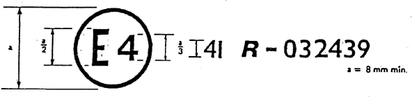
The above approval mark affixed to a motor cycle shows that the motor cycle type concerned has, with regard to noise, been approved in the Netherlands (E 4) pursuant to Regulation No. 41 under approval number 032439. The approval number indicates that the approval was granted according to the requirements of Regulation No. 41 as amended by the 03 series of amendments.
Model B
(See paragraph 5.5. of this Regulation)

The above approval mark affixed to a motor cycle shows that the motor cycle type concerned has been approved in the Netherlands (E 4) pursuant to Regulations Nos. 41 and 33./ The approval numbers indicate that, at the dates when the respective approvals were given, Regulation No. 41 was amended by the 03 series of amendments, but Regulation No. 33 included the 01 series of amendments.
Annex 3
METHODS AND INSTRUMENTS FOR MEASURING NOISE MADE BY MOTOR CYCLES
1. Noise of the motorcycle in motion (measuring conditions and method for testing of the vehicle during component type approval).
1.1. Limits: see annex 6
1.2. Measuring instruments
1.2.1. Acoustic measurements
The apparatus used for measuring the sound level shall be a precision sound-level meter of the type described in International Electrotechnical Commission (IEC) publication 179 "Precision sound-level meters", second edition.
Measurements shall be carried out using the 'fast' response of the sound-level meter and the 'A' weighting also described in that publication.
At the beginning and end of each series of measurements the sound level meter shall be calibrated in accordance with the manufacturer's instructions, using an appropriate sound source (e.g. pistonphone).
1.2.2. Speed measurements
Engine speed and motorcycle speed on the test track shall be determined to within +/- 3
per cent.
1.3. Conditions of measurement
1.3.1. Condition of the motorcycle
During the measurements the motorcycle shall be in running order (including coolant, oils, fuel, tools, spare wheel and rider).
Before the measurements are made the motorcycle shall be brought to the normal operating temperature. If the motorcycle is fitted with fans with an automatic actuating mechanism, this system shall not be interfered with during the sound measurements. For motorcycles having more than one driven wheel, only the drive provided for normal road operation may be used. Where a motorcycle is fitted with a sidecar, this must be removed for the purposes of the test.
1.3.2. Test site
The test site shall consist of a central acceleration section surrounded by a substantially level test area. The acceleration section shall be level; its surface shall be dry and so designed that rolling noise remains low.
On the test site the variations in the free sound field between the sound source at the centre of the acceleration section and the microphone shall be maintained to within 1 dB. This condition will be deemed to be met if there are no large objects which reflect sound, such as fences, rocks, bridges or buildings, within 50 m of the centre of the acceleration section. The road surface covering of the test site shall conform to the requirements of annex 4.
The microphone shall not be obstructed in any way which could affect the sound field, and no person may stand between the microphone and the sound source. The observer carrying out the measurements shall take up position so as not to affect the readings of the measuring instrument.
1.3.3. Miscellaneous
Measurements shall not be made in poor atmospheric conditions. It shall be ensured that the results are not affected by gusts of wind.
For measurements, the A-weighted sound level of sound sources other than those of the motorcycle to be tested and of wind effects shall be at least 10 dB(A) below the sound level produced by the motorcycle. A suitable windscreen may be fitted to the microphone provided that account is taken of its effect on the sensitivity and directional characteristics of the microphone.
If the difference between the ambient noise and the measured noise is between 10 and 16 dB(A), in order to calculate the test results the appropriate correction shall be subtracted from the readings on the sound-level meter, as in the following graph:

1.4. Method of measurement
1.4.1. Nature and number of measurements
The maximum sound level expressed in A-weighted decibels (dB(A)) shall be measured as the motorcycle travels between lines AA' and BB' (figure 1). The measurement will be invalid if an abnormal discrepancy between the peak value and the general sound level is recorded.
At least two measurements shall be taken on each side of the motorcycle.
1.4.2. Positioning of the microphone
The microphone shall be located 7.5 m +/- 0.2 m from the reference line CC (see appendix-Figure 1) of the track and 1.2 m +/- 0.1 m above ground level.
1.4.3. Conditions of operation
The motorcycle shall approach line AA' at an initial steady speed as specified in 1.4.3.1 and 1.4.3.2.When the front of the motorcycle reaches line AA' the throttle shall be fully
opened as quickly as practically possible and kept in that position until the rear of the motorcycle reaches line BB'; the throttle must then be returned as quickly as possible to the idle position.
For all measurements the motorcycle must be ridden in a straight line over the acceleration section keeping the longitudinal median plane of the motorcycle as close as possible to line CC'.
1.4.3.1. Motorcycles with non-automatic gearboxes
1.4.3.1.1. Approach speed
The motorcycle shall approach line AA' at a steady speed of:
(i) 50 km/h
or
(ii) speed corresponding to an engine speed equal to 75 per cent of the speed specified under item 9 of annex 1.
The lower of these speeds shall be selected.
1.4.3.1.2. Selection of gear ratio
1.4.3.1.2.1. Motorcycles fitted with a gearbox having a maximum of four ratios, whatever the
cylinder capacity of their engines, shall be tested only in second gear.
1.4.3.1.2.2. Motorcycles fitted with engines having a cylinder capacity not exceeding 175 cm3 and
a gearbox with five ratio or more shall be tested only in third gear.
1.4.3.1.2.3. Motorcycles fitted with engines having a cylinder capacity of more than 175 cm3 and a gearbox with five ratios or more shall be tested once in second gear and once in third
gear. The result used must be the average of the two tests.
1.4.3.1.2.4. If, during the test carried out in second gear (see paragraphs 1.4.3.1.2.1. and 1.4.3.1.2.3), the engine speed on the approach to the line marking the end of the test track exceeds
100 per cent of the speeds specified under item 9 of annex 1, the test must be carried out in third gear and the sound level measured shall be the only one recorded as the test
result.
1.4.3.2. Motorcycles with automatic gearboxes
1.4.3.2.1. Motorcycles without a manual selector
1.4.3.2.1.1. Approach speed
The motorcycle shall approach line AA' at steady speeds of 30, 40 and 50 km/h or 75 per cent of the maximum road speed if that value is lower. The condition giving the highest sound level is chosen.
1.4.3.2.2. Motorcycles equipped with a manual selector with X forward drive positions.
1.4.3.2.2.1. Approach speed
The motorcycle shall approach line AA' at a steady speed of:
(i) less than 50 km/h, the engine rotation speed being to equal to 75 per cent of the speed specified under item 9 of annex 1,
or
(ii) 50 km/h, the engine rotation speed being less than 75 per cent of the speed specified under item 9 of annex 1.
If, in the test at a steady speed of 50 km/h, the gears change down to first, the approach speed of the motorcycle may be increased to a maximum of 60 km/h to avoid the change down.
1.4.3.2.2.2. Position of the manual selector
If the motorcycle is equipped with a manual selector with X forward drive positions, the test shall be carried out with the selector in the highest position; the voluntary device for changing down (e.g. kickdown) shall not be used. If an automatic change down takes place after line AA', the test shall be begun again using the second highest position or
the third-highest position if necessary, in order to find the highest position or the selector at which the test can be performed without an automatic change down (without using the kickdown).
1.5. Results
1.5.1. The communication referred to in annex 1 shall indicate any circumstances and influences affecting the results of the measurements.
1.5.2. Readings taken shall be rounded off to the nearest decibel.
If the figure following the decimal point is between 0 and 4, the total is rounded down and if between 5 and 9, it is rounded up.
Only those measurements whose variation in two consecutive tests on the same side of the motorcycle is less than or equal to 2 dB(A) may be used for the purpose of issuing
the communication referred to in annex 1.
1.5.3. To take account of inaccuracies in the measurements, the result of each measurement
shall be arrived at by deducting 1 dB(A) from the value obtained in accordance with
1.5.2.
1.5.4. If the average of the four results of the measurements does not exceed the maximum permissible level for the category to which the motorcycle being tested belongs, the limit laid down in paragraph 1.1. will be deemed as being complied with. This average value will constitute the result of the test.
2. Noise from stationary motorcycle (measuring conditions and method for testing of the vehicle in use).
2.1. Sound-pressure level in the immediate vicinity of the motorcycle
In order to facilitate subsequent noise tests on motorcycles in use, the sound-pressure level shall also be measured in the immediate vicinity of the exhaust-system outlet in accordance with the following requirements, the result of the measurement being
entered in the communication referred to in annex 1.
2.2. Measuring instruments
A precision sound-level meter as defined in paragraph 1.2.1. shall be used.
2.3. Conditions of measurement
2.3.1. Condition of the motorcycle
Before the measurements are made the motorcycle engine shall be brought to the normal operating temperature.
If the motorcycle is fitted with fans with an automatic actuating mechanism, this system shall not be interfered with during the sound measurements.
During the measurements the gearbox shall be in neutral gear. If it is impossible to disconnect the transmission, the driving wheel of the motorcycle shall be allowed to rotate freely, for example by placing the vehicle on its centre stand.
2.3.2. Test site (See appendix - figure 2)
Any area in which there are no significant acoustic disturbances may be used as a test site. Flat surfaces which are covered with concrete, asphalt or some other hard material and are highly reflective are suitable; surfaces consisting of earth which has been tamped down shall not be used. The test site must be in the form of a rectangle whose sides are
at least 3 m from the outer edge of the motorcycle (handlebars excluded). There shall be no significant obstacles, e.g. no persons other than the rider and the observer may stand within this rectangle.
The motorcycle shall be positioned within the said rectangle so that the microphone used for measurement is at least 1m from any kerb.
2.3.3. Miscellaneous
Readings of the measuring instrument caused by ambient noise and wind effects shall
be at least 10 dB(A) lower than the sound levels to be measured. A suitable windshield may be fitted to the microphone provided that account is taken of its effect on the sensitivity of the microphone.
2.4. Method of measurement
2.4.1. Nature and number of measurements
The maximum sound level expressed in A-weighted decibels (dB(A)) shall be measured during the period of operation laid down in paragraph 2.4.3.
At least three measurements shall be taken at each measuring point.
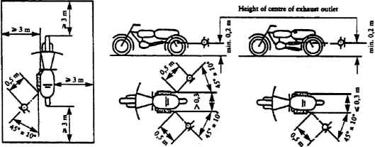
2.4.2. Positioning of the microphone (See appendix - figure 2)
The microphone shall be positioned level with the exhaust outlet or 0.2 m above the surface of the track, whichever is the highest. The microphone diaphram shall face towards the exhaust outlet at a distance of 0.5 m from it. The axis of maximum
sensitivity of the microphone shall be parallel to the surface of the track at an angle of
45 degrees +/- 10' to the vertical plane of the direction of the exhaust emissions.
In relation to this vertical plane, the microphone shall be located on the side which gives the maximum possible distance between the microphone and the outline of the motorcycle (handlebars excluded).
If the exhaust system has more than one outlet at centres less than 0.3 m apart, the microphone shall be faced towards the outlet which is nearest the motorcycle
(handlebars excluded) or towards the outlet which is highest above the surface of the track. If the centres of the outlets are more than 0.3 m apart, separate measurements shall be taken for each of them, the highest figure recorded being taken as the test value.
2.4.3. Operating conditions
The engine speed shall be held steady at one of the following values:
S/2 if S is more than 5,000 rpm,
3S/4, if S is not more than 5,000 rpm
where S is the speed specified under item 9 of annex 1.
When a constant engine speed is reached, the throttle shall be returned swiftly to the idle
position. The sound level shall be measured during an operating cycle consisting of a brief period of constant engine speed and throughout the deceleration period, the maximum sound-level meter reading being taken as the test value.
2.5. Results
2.5.1. The Communication referred to in Annex 1 shall indicate all relevant data and
particularly those used in measuring the noise of the stationary motorcycle.
2.5.2. Values, rounded off to the nearest decibel, shall be read off the measuring instrument.
If the figure following the decimal point is between 0 and 4, the total is rounded down and if between 5 and 9, it is rounded up.
Only those measurements which vary by no more than 2 dB(A) in three consecutive tests will be used.
2.5.3. The highest of the three measurements will constitute the test result.
Annex 3 – Appendix
Figure 1
Test for vehicle in motion
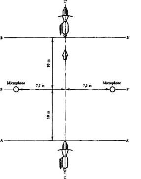
Figure 2
Test for stationary vehicle
Annex 4
SPECIFICATIONS FOR THE TEST SITE
1. Introduction
This annex describes the specifications relating to the physical characteristics and the laying of the test track. These specifications, based on a special standard, [5]/ describe the required physical characteristics as well as the test methods for these characteristics.
2. Required characteristics of the surface
A surface is considered to conform to this standard provided that the texture and voids content or sound absorption coefficient have been measured and found to fulfil [all] the requirements of paragraphs 2.1. to 2.4. below and provided that the design requirements (para. 3.2.) have been met.
2.1. Residual voids content
The residual voids content, Vc, of the test track paving mixture shall not exceed 8 per cent. For the measurement procedure, see paragraph 4.1.
2.2. Sound absorption coefficient
If the surface fails to conform to the residual voids content requirement, the surface is acceptable only if its sound absorption coefficient, alpha, < 0.10. For the measurement procedure, see paragraph 4.2. The requirement of paragraphs 2.1. and 2.2. is met also if only sound absorption has been measured and found to be alpha < 0.10.
Note: The most relevant characteristic is the sound absorption, although the residual voids content is more familiar among road constructors. However, sound absorption needs to be measured only if the surface fails to conform to the voids requirement. This is because the latter is connected with relatively large uncertainties in terms of both measurements and relevance and some surfaces may therefore be rejected erroneously when the voids measurement only is used as a basis.
2.3. Texture depth
The texture depth (TD) measured according to the volumetric method (see para. 4.3. below) shall be:
TD > 0.4 mm
2.4. Homogeneity of the surface
Every practical effort shall be taken to ensure that the surface is made to be as homogeneous as possible within the test area. This includes the texture and voids content, but it should also be observed that if the rolling process results in more effective rolling at some places than others, the texture may be different and unevenness causing bumps may also occur.
2.5. Period of testing
In order to check whether the surface continues to conform to the texture and voids content or sound absorption requirements stipulated in this standard, periodic testing of
the surface shall be done at the following intervals:
(a) For residual voids content or sound absorption:
when the surface is new;
if the surface meets the requirements when new, no further periodical testing is required. If it does not meet the requirement when it is new, it may do later because surfaces tend to become clogged and compacted with time.
(b) For texture depth (TD):
when the surface is new;
when the noise testing starts (NB: not before four weeks after laying);
then every 12 months.
3. Test surface design
3.1. Area
When designing the test track layout it is important to ensure that, as a minimum requirement, the area traversed by the vehicles running through the test strip is covered with the specified test material with suitable margins for safe and practical driving. This will require that the width of the track is at least 3 m and the length of the track extends beyond lines AA and BB by at least 10 m at either end. Figure 1 shows a plan of a suitable test site and indicates the minimum area which shall be machine laid and machine compacted with the specified test surface material. According to annex 3, paragraph 3.1.1.1., measurements have to be made on each side of the vehicle. This can be made either by measuring with two microphone locations (one on each side of the track) and driving in one direction, or measuring with a microphone only on one side of the track but driving the vehicle in two directions. If the former method is used, then there are no surface requirements on that side of the track where there is no microphone.

Note : There shall be no large acoustically reflecting products within this radius.
Figure 1: Minimum requirements for test surface area. The shaded part is called "Test Area".
3.2. Design and preparation of the surface
3.2.1. Basic design requirements
The test surface shall meet four design requirements:
3.2.1.1. It shall be a dense asphaltic concrete.
3.2.1.2. The maximum chipping size shall be 8 mm (tolerances allow from 6.3 to 10 mm).
3.2.1.3. The thickness of the wearing course shall be > 30 mm.
3.2.1.4. The binder shall be a straight penetration grade bitumen without modification.
3.2.2. Design guidelines
As a guide to the surface constructor, an aggregate grading curve which will give desired characteristics is shown in Figure 2. In addition, Table 1 gives some guidelines in order to obtain the desired texture and durability. The grading curve fits the following
formula:
P (% passing) = 100 . (d/dmax)1/2
where: d = square mesh sieve size, in mm
dmax = 8 mm for the mean curve
dmax = 10 mm for the lower tolerance curve
dmax = 6.3 mm for the upper tolerance curve

Figure 2: Grading curve of the aggregate in the asphaltic mix with tolerances.
In addition to the above, the following recommendations are given:
The sand fraction (0.063 mm < square mesh sieve size < 2mm) shall include no more
than 55% natural sand and at least 45% crushed sand;
The base and sub-base shall ensure a good stability and evenness, according to best road construction practice;
The chippings shall be crushed (100% crushed faces) and of a material with a high resistance to crushing;
The chippings used in the mix shall be washed;
No extra chippings shall be added onto the surface;
The binder hardness expressed as PEN value shall be 40-60, 60-80 or even 80-100 depending on the climatic conditions of the country. The rule is that as hard a binder as possible shall be used, provided this is consistent with common practice;
The temperature of the mix before rolling shall be chosen so as to achieve by subsequent rolling the required voids content. In order to increase the probability of satisfying the specifications of paragraphs 2.1. to 2.4. above, the compactness shall be studied not only by an appropriate choice of mixing temperature, but also by an appropriate number of passings and by the choice of compacting vehicle.
Table 1: Design guidelines
| Target values | Tolerances | |
By total | By mass of the aggregate | ||
Mass of stones, square mesh sieve (SM) >2mm Mass of sand 0.063 < SM <2mm Mass of filler SM < 0.063mm Mass of binder (bitumen) Max. chipping size Binder hardness Polished stone value (PSV) Compactness, relative to Marshall compactness | 47.6% 50.5% 38.0% 40.2% 8.8% 9.3% 5.8% N.A. 8mm (see para. 3.2.2. (f)) > 50 98% | +/- 5 +/- 5 +/- 2 +/- 0.5 6.3-10 | |
4. Test method
4.1. Measurement of the residual voids content
For the purpose of this measurement, cores have to be taken from the track in at least four different positions which are equally distributed in the test area between lines AA and BB (see Figure 1). In order to avoid inhomogeneity and unevenness in the wheel tracks, cores should not be taken in wheel tracks themselves, but close to them. Two cores (minimum) should be taken close to the wheel tracks and one core (minimum) should be taken approximately midway between the wheel tracks and each microphone location.
If there is a suspicion that the condition of homogeneity is not met (see para. 2.4.), cores shall be taken from more locations within the test area. The residual voids content has
to be determined for each core, then the average value from all cores shall be calculated and compared with the requirement of paragraph 2.1. In addition, no single core shall have a voids value which is higher than 10%. The test surface constructor is reminded of the problem which may arise when the test area is heated by pipes or electrical wires and cores must be taken from this area. Such installations must be carefully planned with respect to future core drilling locations. It is recommended to leave a few locations of size approximately 200 x 300 mm where there are no wires/pipes or where the latter are located deep enough in order not to be damaged by cores taken from the surface layer.
4.2. Sound absorption coefficient
The sound absorption coefficient (normal incidence) shall be measured by the impedance tube method using the procedure specified in ISO 10534:1994 - "Acoustics - Determination of sound absorption coefficient and impedance by a tube method."
Regarding test specimens, the same requirements shall be followed as regarding the residual voids content (see para. 4.1.). The sound absorption shall be measured in the range between 400 Hz and 800 Hz and in the range between 800 Hz and 1,600 Hz (at least at the centre frequencies of third octave bands) and the maximum values shall be identified for both of these frequency ranges. Then these values, for all test cores, shall be averaged to constitute the final result.
4.3. Volumetric macro texture measurement
For the purpose of this standard, texture depth measurements shall be made on at least 10 positions evenly spaced along the wheel tracks of the test strip and the average value taken to compare with the specified minimum texture depth. For the description of the procedure see standard ISO 10844:1994.
5. Stability in time and maintenance
5.1. Age influence
In common with any other surfaces, it is expected that the tyre/road noise level measured on the test surface may increase slightly during the first 6-12 months after construction.
The surface will achieve its required characteristics not earlier than four weeks after construction. The influence of age on the noise from trucks is generally less than that from cars.
The stability over time is determined mainly by the polishing and compaction by vehicles driving on the surface. It shall be periodically checked as stated in paragraph 2.5.
5.2. Maintenance of the surface
Loose debris or dust which could significantly reduce the effective texture depth must be removed from the surface. In countries with winter climates, salt is sometimes used for de-icing. Salt may alter the surface temporarily or even permanently in such a way as to increase noise and is therefore not recommended.
5.3. Repaving the test area
If it is necessary to repave the test track, it is usually unnecessary to repave more than the test strip (of 3 m width in Figure 1) where vehicles are driving, provided the test area outside the strip met the requirement of residual voids content or sound absorption when it was measured.
6. Documentation of the test surface and of tests performed on it
6.1. Documentation of the test surface
The following data shall be given in a document describing the test surface:
6.1.1. The location of the test track.
6.1.2. Type of binder, binder hardness, type of aggregate, maximum theoretical density of the concrete (DR), thickness of the wearing course and grading curve determined from cores from the test track.
6.1.3. Method of compaction (e.g. type of roller, roller mass, number of passes).
6.1.4. Temperature of the mix, temperature of the ambient air and wind speed during laying of the surface.
6.1.5. Date when the surface was laid and contractor.
6.1.6. All or at least the latest test results, including:
6.1.6.1. The residual voids content of each core.
6.1.6.2. The locations in the test area from where the cores for voids measurements have been taken.
6.1.6.3. The sound absorption coefficient of each core (if measured).
Specify the results both for each core and each frequency range as well as the overall average.
6.1.6.4. The locations in the test area from where the cores for absorption measurement have been taken.
6.1.6.5. Texture depth, including the number of tests and standard deviation.
6.1.6.6. The institution responsible for tests according to paragraphs 6.1.6.1. and 6.1.6.2. and the type of equipment used.
6.1.6.7. Date of the test(s) and date when the cores were taken from the test track.
6.2. Documentation of vehicle noise tests conducted on the surface
In the document describing the vehicle noise test(s) it shall be stated whether all the requirements of this standard were fulfilled or not. Reference shall be given to a document according to paragraph 6.1. describing the results which verify this.
Annex 5
EXHAUST SYSTEM (SILENCER)
1.1. After removal of the fibrous material, the sound level must comply with the requirements of annex 3 and the sound level limits of annex 4.
1.2. The fibrous absorbent material may not be placed in those parts of the silencer through which the exhaust gases pass and must comply with the following requirements:
1.2.1. The material must be heated at a temperature of 650 +/- 5 degrees C for four hours in a furnace without reduction in every length, diameter or bulk density of the fibre.
1.2.2. After heating at 650 +/- 5 degrees C for one hour in a furnace, at least 98% of the material must be retained in a sieve of nominal aperture size 250 mu m complying with ISO Standard 3310/1 : 1990 when tested in accordance with ISO Standard 2599 : 1983.
1.2.3. The loss in weight of the material must not exceed 10.5% after soaking for 24 hours at 90 +/- 5 degrees C in a synthetic condensate of the following composition:
1 N hydrobromic acid (HBr): 10 ml
1 N sulphuric acid (H2SO4): 10 ml
Distilled water to make up to 1,000 ml.
Note: The material must be washed in distilled water and dried for one hour at 105 degrees C before weighing.
1.3. Before the system is tested in accordance with annex 3, it must be put into a normal state for road use by one of the following condition methods:
1.3.1. CONDITIONING BY CONTINUOUS ROAD OPERATION
1.3.1.1. According to the classes of motor cycles, the minimum distances to be completed during conditioning are:
Class of motor cycle according to cylinder capacity in cm3 | Distance (km) |
Class I < 80 Class II > 80 < 175 Class III > 175 | 4,000 6,000 8,000 |
1.3.1.2. 50 +/- 10% of this conditioning cycle consists of town driving and the remainder of long- distance runs at high speed; the continuous road cycle may be replaced by a corresponding test-track programme.
1.3.1.3. The two speed regimes must be alternated at least six times.
1.3.1.4. The complete test programme must include a minimum of 10 breaks of at least three hours' duration in order to reproduce the effects of cooling and condensation.
1.3.2. CONDITIONING BY PULSATION
1.3.2.1. The exhaust system or components thereof must be fitted to the motor cycle or to the engine. In the former case, the motor cycle must be mounted on a test bench.
The test apparatus, a detailed diagram of which is shown in Figure 1, is fitted at the outlet of the exhaust system. Any other apparatus providing equivalent results is acceptable.
1.3.2.2. The test equipment must be adjusted so that the flow of exhaust gases is alternatively interrupted and restored 2,500 times by a rapid-action valve.
1.3.2.3. The valve must open when the exhaust gas back-pressure, measured at least 100 mm downstream of the intake flange, reaches a value of between 0.35 and 0.40 bar. Should such a figure be unattainable because of the engine characteristics, the valve must open when the gas back-pressure reaches a level equivalent to 90% of the maximum that can be measured before the engine stops. It must close when this pressure does not differ by more than 10% from its stabilized value with the valve open.
1.3.2.4. The time-delay switch must be set for the duration of exhaust gases calculated on the basis of the requirements of paragraph 1.3.2.3.
1.3.2.5. Engine speed must be 75% of the speed (S) at which the engine develops maximum power.
1.3.2.6. The power indicated by the dynamometer must be 50% of the full-throttle power measured at 75% of engine speed (S).
1.3.2.7. Any drainage holes must be closed off during the test.
1.3.2.8. The entire test must be complete within 48 hours. If necessary, a cooling period must be allowed after each hour.
1.3.2. CONDITIONING ON A TEST BENCH
1.3.3.1. The exhaust system must be fitted to an engine representative of the type fitted to the motor cycle for which the exhaust system was designed, and mounted on a test bench.
1.3.3.2. Conditioning consists of the specific number of test bench cycles for each class of motor cycle for which the exhaust system was designed. The number of cycles for each class
of motor cycle is:
Class of motor cycle according to cylinder capacity in cm3 | Number of cycles |
Class I < 80 Class II > 80 < 175 Class III > 175 | 6 9 12 |
1.3.3.3. Each test-bench cycle must be followed by a break of at least six hours in order to reproduce the effects of cooling and condensation.
1.3.3.4. Each test-bench cycle consists of six phases. The engine conditions for and the duration of each phase are:
Phase | Conditions | Duration of phase | |
Engines < 175 cm3 | Engines > 175 cm3 | ||
1 2 3 4 5 6 | Idling 25% load at 75% S 50% load at 75% S 100% load at 75% S 50% load at 100% S 25% load at 100% S | (minutes) 6 40 40 30 12 22 | (minutes) 6 50 50 10 12 22 |
| Total time | 2.5 hours | 2.5 hours |
1.3.3.5 During this conditioning procedure, at the request of the manufacturer, the engine and
the silencer may be cooled in order that the temperature recorded at a point not more than 100 mm from the exhaust gas outlet does not exceed that measured when the motor cycle is running at 110 km/h or 75% S in top gear. The engine and/or motor cycle speeds are determined to within +/- 3%.
Figure 1
TEST APPARATUS FOR CONDITIONING BY PULSATION

1. Inlet flange or sleeve for connection to the rear of the test exhaust system.
2. Hand-operated regulating valve.
3. compensating reservoir with a maximum capacity of 40 litres.
4. Pressure switch with an operating range of 0.05 to 2.5 bar.
5. Time delay switch.
6. Impulse counter.
7. Quick response valve, such as exhaust brake valve 60 mm in diameter, operated by a pneumatic cylinder with an output of 120 N at 4 bar. The response time, both when opening and closing, must not exceed 0.5 seconds.
8. Exhaust gas evacuation.
9. Flexible pipe.
10. Pressure gauge.
Annex 6
MAXIMUM LIMITS OF SOUND LEVEL (NEW MOTOR CYCLES)
Category of motorcycle | Engine cylinder capacity (cc) | Values expressed in dB(A) |
First category | cc < 80cm3 | 75 |
Second category | 80cm3< cc < 175cm3 | 77 |
Third category | cc > 175cm3 | 80 |
______________
[1]/ 1 Germany, 2 for France, 3 for Italy, 4 for the Netherlands, 5 for Sweden, 6 for Belgium, 7 for Hungary, 8 for
the Czech Repubic, 9 for Spain, 10 for Yugoslavia, 11 for the United Kingdom, 12 for Austria, 13 for Luxembourg, 14 for Switzerland, 15 (vacant), 16 for Norway, 17 for Finland, 18 for Denmark, 19 for Romania, 20 for Poland,
21 for Portugal, 22 for the Russian Federation, 23 for Greece, 24 for Ireland, 27 for Slovakia, 28 for Belarus, 29
for Estonia, 30 (vacant), 31 for Bosnia and Herzegovina, 32 for Latvia, 33-36 (vacant), 37 for Turkey, 38-39 (vacant) 40 for the former Yugoslav Republic of Macedonia, 41 (vacant), 42 for the European Community (Approvals are granted by its Member States using their respective ECE symbol) and 43 for Japan. Subsequent numbers shall be assigned to other countries in the chronological order in which they ratify the Agreement Concerning the Adoption for Uniform Technical Prescriptions for Wheeled Vehicles, Equipment and Parts which can be fitted and/or be Used on Wheeled Vehicles, and the Conditions for Reciprocal Recognition of Approval Granted on the Basis of these Prescriptions, and the numbers thus assigned shall be communicated by the
Secretary-General of the United Nations to the Contracting Parties to the Agreement.
[2]/ A test is made on a stationary motor cycle in order to provide a reference value for administrations which use this method to check motor cycles in use.
[3]/ If a non-conventional engine is used, this should be stated
[4]/ Strike out whatever does not apply.
/ The latter number is given as an example only.
[5]/ ISO 10844: 1994