Attachment A
COMMONWEALTH OF AUSTRALIA
Sections 226 and 708
Offshore Petroleum and Greenhouse Gas Storage Act 2006
APPLICATION FOR VARIATION OF A PIPELINE LICENCE – PIPELINE LICENCE WA-20-PL
I, GRAEME ALBERT WATERS, the National Offshore Petroleum Titles Administrator, on behalf of the Commonwealth–Western Australia Offshore Petroleum Joint Authority hereby give notice pursuant to sections 226 and 708 of the Offshore Petroleum and Greenhouse Gas Storage Act 2006 that an application has been received from
Chevron Australia Pty Ltd
(ACN 086 197 757)
Chevron (TAPL) Pty Ltd
(ACN 081 647 047)
Mobil Australia Resources Company Pty Limited
(ACN 000 113 217)
Shell Australia Pty Ltd
(ACN 009 663 576)
Osaka Gas Gorgon Pty Ltd
(ACN 139 074 847)
Tokyo Gas Gorgon Pty Ltd
(ACN 138 592 042)
JERA Gorgon Pty Ltd
(ACN 140 107 464)
for the variation of Pipeline Licence WA-20-PL in the offshore area of Western Australia, as set out below.
Pursuant to subsection 226(3) of the Act, a person may make a written submission to the Titles Administrator about this application within 30 days from the date of this notice.
This notice takes effect on the day on which it appears in the
Australian Government Gazette.
Made under the Offshore Petroleum and Greenhouse Gas Storage Act 2006
of the Commonwealth of Australia.
GRAEME ALBERT WATERS
TITLES ADMINISTRATOR
ON BEHALF OF THE COMMONWEALTH–WESTERN AUSTRALIA
OFFSHORE PETROLEUM JOINT AUTHORITY
APPLICATION FOR VARIATION OF
PIPELINE LICENCE WA-20-PL
The application seeks to effect the following administrative amendments to the licence:
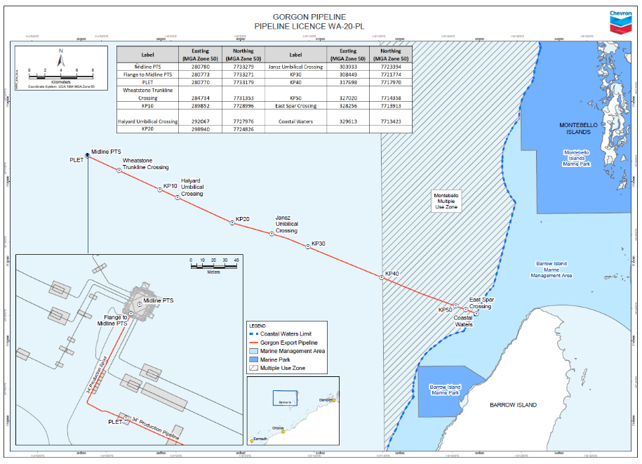
Feature Name | Easting (MGA Zone 50) | Northing (MGA Zone 50) |
Midline PTS | 280780 | 7733279 |
Flange to Midline PTS | 280773 | 7733271 |
PLET | 280770 | 7733179 |
Wheatstone Trunkline Crossing | 284734 | 7731353 |
KP 10 | 289852 | 7728996 |
Halyard Umbilical Crossing | 292067 | 7727976 |
KP 20 | 298940 | 7724826 |
Jansz Umbilical Crossing | 303933 | 7723394 |
KP 30 | 308449 | 7721774 |
KP 40 | 317698 | 7717970 |
KP 50 | 327020 | 7714358 |
East Spar Crossing | 328256 | 7713913 |
Coastal Waters | 329613 | 7713423 |
2. Update Annexure “C”, Basis of Design table with the details marked in bold below:
General Details | ||||||||||||||||||||||||
1. | Pipeline Name (meaningful to industry): | Gorgon Commonwealth Waters Pipeline | ||||||||||||||||||||||
2. | Start Point Description: | Midline PTS | ||||||||||||||||||||||
3. | ‘Start’ Point of Pipeline Coordinates (GDA94): a) Northing: b) Easting: |
a) Northing: 7733279 mN b) Easting: 280780 mE | ||||||||||||||||||||||
4. | End Point Description: | 3 Nm seaward of MLWM | ||||||||||||||||||||||
5. | ‘End’ Point of Pipeline Coordinates (GDA94): a) Northing: b) Easting: |
a) Northing: 7713423 mN b) Easting: 329613 mE | ||||||||||||||||||||||
6. | Substance to be Conveyed: | Wet Gas – Predominately Methane with approx 14% CO2 | ||||||||||||||||||||||
7. | Characteristics of Substance to be Conveyed: a) Gas Composition:
b) Oil Viscosity (centistokes): c) Flashpoint of Oil: d) Operating Temperature Range °C |
a) Gas Composition
b) N/A c) N/A d) 7 to 28 °C | ||||||||||||||||||||||
Design Details | ||||||||||||||||||||||||
8. | Pipe Dimensions a) Outside Diameter (mm): b) Length of Pipeline (km): |
a) 876 mm b) 52.87 km | ||||||||||||||||||||||
9. | Nominal Wall Thickness a) Standard Wall (mm): b) Heavy Wall (mm): |
a) 38.0 mm b) N/A | ||||||||||||||||||||||
10. | Joint Type (Welded, Mechanical etc): | Butt welded | ||||||||||||||||||||||
11. | Design (at standard conditions) a) Initial Design Capacity (MMscf/d): b) Maximum Design Capacity (MMscf/d): c) Design Life (Years): d) Erosional Velocity (m/s): |
a) 1909 MMscf/d b) 1909 MMscf/d c) 50 years d) 30.5 m/s | ||||||||||||||||||||||
12. | Pipeline Corrosion Allowance a) Internal (mm):
b) External (mm): |
a) Internal: 4.5mm (KP 0 to 30) 3.0mm (KP 30 to 52.87) b) External: 0.0 mm | ||||||||||||||||||||||
13. | Pipe Free Span (m) at Location (KP): | Assessed using FEA on pipeline digital twin | ||||||||||||||||||||||
14. | Pipe Steel Specification and Grade: (a) Pipeline:
(b) Riser: |
a) Carbon steel suitable for sour service, DNVGL-ST-F101 DNV SAWL 450 SFDU b) N/A | ||||||||||||||||||||||
15. | Minimum Yield Strength of Pipe Steel: | 450 MPag | ||||||||||||||||||||||
Temperature & Pressure Details | ||||||||||||||||||||||||
16. | Design Temperature: a) Pipeline °C: b) Facilities °C: |
a) 0 to 50 °C (for Commonwealth) b) N/A | ||||||||||||||||||||||
17. | Maximum Operating Temperature a) Pipeline °C: b) Facilities/Stations °C (Normal): |
a) 28 °C b) N/A | ||||||||||||||||||||||
18. | Minimum Operating Temperature a) Pipeline °C: b) Facilities/Stations °C (Normal): |
a) Pipeline 7 °C b) Facilities: N/A | ||||||||||||||||||||||
19. | Design Pressure (MPag): | 29.9 MPag @ 130 m WD | ||||||||||||||||||||||
20. | Inlet Pressure Range (kPag): | 8,000 to 14,600 kPag | ||||||||||||||||||||||
21. | Outlet Pressure Range (kPag): | 8,000 to 14,600 kPag | ||||||||||||||||||||||
22. | Field Test Pressure a) Proposed Field Test Pressure: b) Minimum Field Test Pressure [ ] x MAOP = [ ] MPag: |
a) 36.5 MPag @ 130 m WD b) Leak tested to 369 barg – 24 hours @ 130 m WD | ||||||||||||||||||||||
23. | Maximum Allowable Operating Pressure (MAOP) a) MPag at °C for Pipeline:
b) MPag at °C for Facilities/Station: |
a) MAOP is 20 MPag at max operating temp @ 130 m WD b) N/A | ||||||||||||||||||||||
Pipeline Coatings | ||||||||||||||||||||||||
24. | Protective External Coating Specification and Thickness (mm): | FBE 0.735 mm | ||||||||||||||||||||||
25. | Weight Coating Design Specification and Thickness (mm): | AS 1397 65 to 90 mm | ||||||||||||||||||||||
26. | Field Joint Coating: | FBE + PUF Infill (PUF required where concrete coating applied) | ||||||||||||||||||||||
27. | Pipe-to-Pipe Joint Coating: | FBE + PUF Infill (PUF required where concrete coating applied) | ||||||||||||||||||||||
Control Monitoring | ||||||||||||||||||||||||
28. | Pressure and Flow Controls Description: | Pipeline isolation shall be via the subsea isolation valves and the pipeline isolation valves located within the pig receiver station at the LNG plant. The design uses an Instrumented Over pressure Protection System (IOPPS), located at each subsea production centre, with a design pressure less than well-head shut-in pressure (WHSIP), from over-pressure events. This system complies with AS 2885.4. | ||||||||||||||||||||||
29. | Safety and Emergency Shutdown Description: | If an emergency situation occurs that threatens a MODU working above producing subsea facilities (e.g. dropped object), activation of a hand switch or defined loss of communications from MODU will initiate a MODU ESD. This isolates the Gorgon or Jansz wells and production flowline at the manifold where the MODU is working (the MODU has control of the well it is working on), to minimise any potential consequences. The MODU ESD is transmitted to the Gorgon GTP, isolating all wells on the manifold where the MODU is located. | ||||||||||||||||||||||
30. | Telemetry Control: | Fibre-optic cables provide primary communication. Electric power cables provide power to the subsea equipment, and serve as the communications path for the backup copper-based communications system. | ||||||||||||||||||||||
31. | Pigging Facilities: a) General Facilities:
b) Description of Pigging Facilities: |
a) Permanent pig receiver is located in the inlet area of the LNG plant. Design pressure is 36,000 kPa design temperature is 75 °C (max); -46 °C (min). b) Permanent pig receiver will be sized to accommodate the latest generation intelligent pig and shall be capable of launching and receiving. | ||||||||||||||||||||||
32. | Provisions for cathodic protection of the pipeline: | Offshore: Sacrificial anodes | ||||||||||||||||||||||
33. | Cathodic Potential Monitoring: | Yes | ||||||||||||||||||||||
34. | Cathodic Protection Test Posts: | N/A | ||||||||||||||||||||||
Valves & Inline Facilities | ||||||||||||||||||||||||
35. | Fittings, Valves and Flanges Specifications a) Fittings: b) Valves: c) Flanges: | In accordance with DNV-OS-F101 a) Fittings: ASMEB16.9 b) Valves: API 6D, NACE MR0175 c) Flanges: N/A | ||||||||||||||||||||||
36. | Mainline Valves – a) Number of: b) Type: c) Location (at KP): d) Details of Mainline Valves: | N/A | ||||||||||||||||||||||
37. | Location of future Off-take Tees (at KP): | N/A | ||||||||||||||||||||||
38. | Number of Pipeline Inlet Facilities: | 1 | ||||||||||||||||||||||
39: | Pipeline Inlet Facilities Description: | Diverless PLET | ||||||||||||||||||||||
40. | Number of Pipeline Outlet Facilities: | 1 | ||||||||||||||||||||||
41. | Pipeline Outlet Facilities Description: | Butt Welded | ||||||||||||||||||||||
42. | Compressor Stations (if applicable) a) Number of: b) Location (at KP): | N/A | ||||||||||||||||||||||
43. | Other Inline Facilities: | Corrosion monitoring spool prior to inlet of flowline (on the tie-in spool) | ||||||||||||||||||||||
Crossings & Pipeline Stabilisation | ||||||||||||||||||||||||
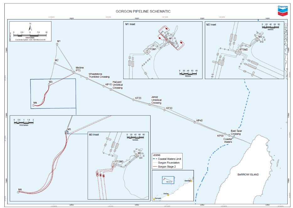
44. | Location of the crossing: | Pipeline crossing locations are documented on Gorgon Pipeline – Overview of Pipeline Route | ||||||||||||||||||||||
45. | Pipeline Crossing Type: | Achieved using pipe supports (mattresses) to cross over Apache East Spar Pipeline. Rock dumped for stabilisation. | ||||||||||||||||||||||
46. | Crossings Design Standard: | AS 2885.4 | ||||||||||||||||||||||
47. | Minimum Earth Cover or Other Means of Stabilisation: | Rock Dump | ||||||||||||||||||||||
48. | Anchoring Details: | N/A | ||||||||||||||||||||||
Pipeline Management | ||||||||||||||||||||||||
49. | Environmental Design Criteria Description: | Designed to withstand 100 year return period storm levels; Erosion mitigation measures based on hydrological surveys; Minimised flora disturbance based on vegetation surveys; ROW minimised to restrict land disturbance. | ||||||||||||||||||||||
50. | Marine Growth Allowance (mm): | Less than 60 m WD = 30 mm 60 m to 130 m WD = 10 mm | ||||||||||||||||||||||
51 | Risk Management Description: | Gorgon Upstream has a Risk Management Policy aligned to the principles of AS/NZS4360: Risk Management. Formal safety assessments and risk assessment will be in accordance with AS2885.1. The Pipeline Risk Management is included in the Formal Safety Assessment; document number G1-NT-REP-J0005. | ||||||||||||||||||||||
Attachment A